Parker MA3 Series User manual

Mobile Products
MA3 Series Mobile Inverter
User Manual
HA473434 Issue 3
© 2013 Parker Hannifin, SSD Drives Division
All rights strictly reserved. No part of this document may be stored in a
retrieval system, or transmitted in any form or by any means to persons not
employed by a Parker SSD Drives company without written permission from
Parker SSD Drives, a division of Parker Hannifin. Although every effort has
been taken to ensure the accuracy of this document it may be necessary,
without notice, to make amendments or correct omissions. Parker SSD
Drives cannot accept responsibility for damage, injury, or expenses resulting
therefrom.
WARRANTY
Parker SSD Drives warrants the goods against defects in design, materials
and workmanship for the period of 24 months from the date of manufacture,
or 12 months from the date of delivery (whichever is the longer period), on
the terms detailed in Parker SSD Drives Standard Conditions of Sale. Parker
SSD Drives reserves the right to change the content and product
specification without notice.

Page 2
Table of Contents
Table of Contents ..................................................................................................... 2
1Safety................................................................................................................. 4
1.1 Requirements..................................................................................................4
1.1.1 INTENDED USERS ...........................................................................................4
1.1.2 User Safety Responsibility Statement for All Parker Products.......................5
1.1.3 PERSONNEL.........................................................................................................5
1.1.4 PRODUCT WARNING...........................................................................................5
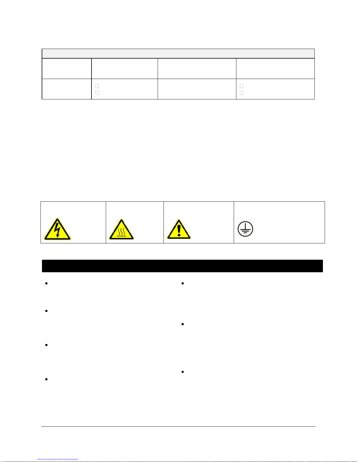
1.1.5 HAZARDS.............................................................................................................. 5
1.1.6 User Safety Responsibility Statement for All Parker Products.......7
2Scope of Delivery ........................................................................................... 8
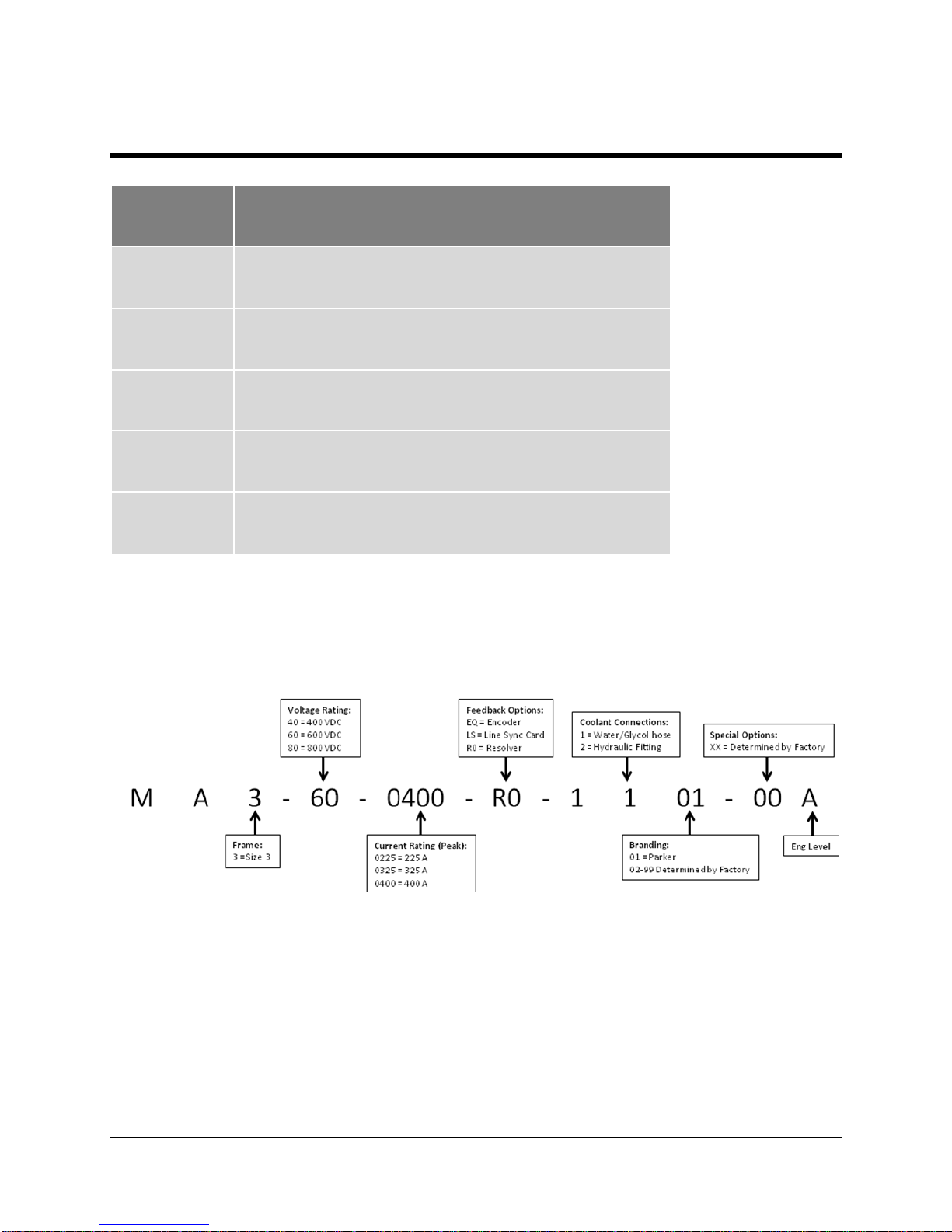
2.1 Product Code ..................................................................................................8
2.2 Equipment Inspection ..................................................................................9
Storage and Shipping Temperatures ..................................................................... 9
Packaging and Lifting Information ......................................................................9
3Product Introduction................................................................................... 10
Product Overview....................................................................................................10
Specification ............................................................................................................10
Electrical .......................................................................................................................10
Environment .................................................................................................................13
3.1 General Product Description....................................................................15
3.1.1 J1 Connector –I/O Wiring Information ...................................................15
3.1.2 J2 Connector –Motor Feedback Wiring Information.........................16
3.1.3 Block Diagram ................................................................................................17
3.1.4 Example System Diagram...........................................................................18
4Product Installation..................................................................................... 19
4.1 Mechanical Installation in a Mobile Environment .............................19
4.1.1 Dimensions and Weight ...............................................................................19
4.1.2 Mounting ...........................................................................................................20
4.1.3 Installation Orientation ...............................................................................20
4.2 Cooling Requirements................................................................................20
4.2.1 Specification ...................................................................................................21
4.2.2 Hose Clamping Instructions ......................................................................22
4.2.3 Parallel Configuration ..................................................................................23
4.3 Wiring Power Cables...................................................................................24
4.4 J1/J2 Mating Connectors ..........................................................................27
4.5 Pre-Charge Circuit.......................................................................................28
4.6 Grounding.......................................................................................................29

Page 3
5Operations ...................................................................................................... 30
5.1 Commissioning .............................................................................................30
5.2 Power-Up Sequence....................................................................................31
6Software.......................................................................................................... 31
6.1 Introduction...................................................................................................31
6.2 Installation ....................................................................................................32
6.3 Connecting to the Inverter .......................................................................33
6.4 Configurations ..............................................................................................34
6.4.1 Creating a Configuration.............................................................................34
6.4.2 Modifying a Configuration...........................................................................36
6.4.3 Installing a Configuration ...........................................................................40
6.4.4 Updating a Configuration............................................................................40
6.5 Charting Functions......................................................................................42
6.6 CANopen.........................................................................................................44
6.6.1 Introduction .....................................................................................................44
6.6.2 Configuring a CANopen System ...............................................................44
6.6.3 External Control of Inverter .......................................................................52
6.6.4 CANopen Termination..................................................................................57
7Appendix ......................................................................................................... 58
7.1 DSE Lite/CANopen Conversion Rule.......................................................58
7.1.1 Regulatory Compliance ...............................................................................61
7.1.2 European Compliance ..................................................................................62
7.2 EMC Installation Guidance .......................................................................63
7.2.1 Protective Earth (PE Connections)..........................................................63
7.2.2 MITIGATING THE EFFECTS OF RADIATED INTERFERENCE .......................63
7.2.3 CABLING REQUIREMENTS .........................................................................64
7.3 Environmental..................................................................................................65
7.3.1 RESTRICTIONS, EVALUATION, AUTHORISATION AND
RESTRICTION OF CHEMICALS (REACH)................................................65
7.3.2 WASTE ELECTRICAL AND ELECTRONIC EQUIPMENT (WEEE) ..................65
7.4 North American Compliance...........................................................................66
7.4.1 Requirements for North American Compliance ..................................66

Page 4
1 Safety
Safety Information
Please read these important Safety notes before installing and operating this equipment
DANGER
DANGER –High risk –Notes in the manual warn of danger to personnel typically severe injury
or death
WARNING
WARNING –Medium risk - Notes in the manual warn of danger to personnel typically injury
CAUTION
CAUTION –Low risk - Notes in the manual warn of potential equipment damage
Note: notifications assist the user with helpful tips for making operations and maintenance
easier and more efficient.
1.1 Requirements
1.1.1 INTENDED USERS
This manual is to be made available to all persons who are required to install, configure or service
equipment described herein, or any other associated operation.
The information given is intended to highlight safety issues, and to enable the user to obtain maximum
benefit from the equipment.

Complete the following table for future reference detailing how the unit is to be installed and used.
INSTALLATION DETAILS
Model Number
(see product
label)
Where installed
(for your own
information)
Unit used as a:
(refer to
Certification)
Component
Relevant Apparatus
Unit fitted:
Cubicle mounted
Through Panel Mounted
1.1.2 User Safety Responsibility Statement
for All Parker Products
The equipment described is intended for industrial motor speed control utilising AC induction motors or
AC permanent magnet synchronous machines.
1.1.3 PERSONNEL
Installation, operation and maintenance of the equipment should be carried out by competent personnel.
A competent person is someone who is technically qualified and familiar with all safety information and
established safety practices; with the installation process, operation and maintenance of this equipment;
and with all the hazards involved.
1.1.4 PRODUCT WARNING
1.1.5 HAZARDS
DANGER - Ignoring the following may result in server injury or death
This equipment can endanger life by
exposure to rotating machinery and high
voltages.
The equipment must be permanently earthed
due to the high earth leakage current, and the
drive motor must be connected to an
appropriate safety earth.
Ensure all incoming supplies are isolated
before working on the equipment. Be aware
that there may be more than one supply
connection to the drive.
There may still be dangerous voltages
present at power terminals (motor output,
supply input phases, DC bus and the brake,
where fitted) when the motor is at standstill or
is stopped.
For measurements use only a meter to IEC
61010 (CAT III or higher). Always begin using the
highest range.
CAT I and CAT II meters must not be used on
this product.
Allow at least 5 minutes for the drive's capacitors
to discharge to safe voltage levels (<50V). Use
the specified meter capable of measuring up to
1000V dc & ac rms to confirm that less than 50V
is present between all power terminals and
between power terminals and earth.
Unless otherwise stated, this product must NOT
be dismantled. In the event of a fault the drive
must be returned. Refer to "Routine Maintenance
and Repair".
DANGER
Risk of electric shock
WARNING
Hot surfaces
Caution
Refer to documentation
Earth/Ground
Protective Conductor Terminal

Page 6
WARNING - Ignoring the following may result in injury or equipment damage
SAFETY
Where there is conflict between EMC and Safety requirements, personnel safety shall always take
precedence.
Never perform high voltage resistance checks
on the wiring without first disconnecting the drive
from the circuit being tested.
Whilst ensuring ventilation is sufficient,
provide guarding and /or additional safety
systems to prevent injury or damage to
equipment.
When replacing a drive in an application and
before returning to use, it is essential that all user
defined parameters for the product’s operation
are correctly installed.
All control and signal terminals are SELV, i.e.
protected by double insulation. Ensure all external
wiring is rated for the highest system voltage.
Thermal sensors contained within the motor must
have at least basic insulation.
All exposed metalwork in the Inverter is protected
by basic insulation and bonded to a safety earth.
RCDs are not recommended for use with this
product but, where their use is mandatory, only Type
B RCDs should be used.
CAUTION - Ignoring the following may result in injury or damage to equipment
APPLICATION RISK
The specifications, processes and circuitry described herein are for guidance only and may need
to be adapted to the user’s specific application. We can’t guarantee the suitability of the equipment
described in this Manual for individual applications.
RISK ASSESSMENT
Under fault conditions, power loss or unintended operating conditions, the drive may not operate as
intended. In particular:
Stored energy might not discharge to safe
levels as quickly as suggested, and can still
be present even though the drive appears
to be switched off
The motor's direction of rotation might not be
controlled
The motor speed might not be controlled
The motor might be energised
A drive is a component within a drive system that may influence its operation or effects under a fault
condition. Consideration must be given to:
Stored energy
Supply disconnects
Sequencing logic
Unintended operation

1.1.6 User Safety Responsibility Statement
for All Parker Products
This document and other information from Parker Hannifin Corporation, its subsidiaries,
and authorized distributors, provide product and/or system options for further
investigation by users having technical expertise.
Through their own analysis and testing, users are solely responsible for making the final
selection of system and components, and assuring that all performance, endurance,
maintenance, safety, and warning requirements of the application are met. The user must
analyze all aspects of the application, follow applicable industry standards, and follow the
information concerning the product in the current product catalog and in any other
materials provided from Parker or its subsidiaries or authorized distributors.
To the extent that Parker or its subsidiaries or authorized distributors provide component
or system options based upon data or specifications provided by the user, the user is
responsible for determining that such data and specifications are suitable and sufficient
for all applications and reasonably foreseeable uses of the components or systems.
The products described herein, including without limitation, product features,
specifications, designs, availability, and pricing, are subject to change by Parker Hannifin
Corporation and its subsidiaries at any time without notice.

Page 8
2 Scope of Delivery
Qty
Item
1
Mobile Inverter
1
Software CD - DSE Lite
1
USB Cable
12
Screws M3 x 8
5
Terminal Ferrules
2.1 Product Code
Part Number Breakdown

2.2 Equipment Inspection
When inspecting equipment:
Check for signs of transit damage
Check the product code on the rating label to make sure it conforms to your requirement
If you do not install the unit immediately, store it in a well-ventilated location, away from
extreme temperatures, humidity, dust, or metal particles.
Storage and Shipping Temperatures
Storage
-40°C to +80°C (-40°F to +176°F)
Shipping
-40°C to +80°C (-40°F to +176°F)
Packaging and Lifting Information
Save packaging for returning the product if needed.
Improper packaging may result in transit damage!
Use safe and suitable lifting procedures when moving the unit.
Never lift the unit by its terminal connections!
Prepare an open, flat surface to place the inverter before attempting to move it.
Do not damage any terminal connections when placing the inverter.
Caution - Packaging is combustible. Igniting the packaging results in toxic
fumes.

Page 10
3 Product Introduction
Product Overview
The Parker SSD MA3 inverter is designed to control standard 3-phase permanent magnet
synchronous motors and AC induction motors. The inverter is capable of 4-quadrant motor
control which enables the motor to also act as a generator. The MA3 normally operates in a
Closed-Loop Vector mode; however the inverter can be configured to operate in Sensorless and
V/Hz mode.
Motor speed feedback is provided by a resolver or quadrature encoder mounted on the motor
shaft. The speed loop has amendable bi-directional speed demand, ramp, and torque limits.
When regenerating, motors operate with a saturated speed loop, such as in torque mode with a
speed limit.
Specification
Electrical
Input Voltage –Control Supply
Nominal Voltage
7 Vdc to 32 Vdc
Overvoltage
36 Vdc (max 5 min)
Reverse Voltage
-36 Vdc (max 5 min)
Max Control Current @ 7V
8 Adc
Max Control Current @ 32 V
0.7 Adc
Max Inrush Current
18.9 Adc (max 50ms)

Input Voltage –DC Bus Ratings
Inverter
Operating Range
(Vdc)
Nominal
(Vdc)
Undervoltage
Trip (Vdc)
Overvoltage
Trip (Vdc)
MA3-40-xxxx
210 - 400
320
205
410
MA3-60-xxxx
315-600
480
310
615
MA3-80-xxxx
420-800
640
410
820
DC Bus Capacitance
Model
DC link capacitance
MA3-40-xxxx
600 μF
MA3-60-xxxx
600 μF
MA3-80-xxxx
400 μF
DANGER - THESE DEVICES CONTAIN STORED ENERGY, LETHAL
VOLTAGES PERSIST AFTER DE-ENERGISATION.
CARELESSLY HANDLING THESE DEVICES MAY CAUSE DEATH, PERSONAL
INJURY, AND PROPERTY DAMAGE!
The bus must be discharged prior to removal or working on or near the inverter. Use a voltmeter
to measure DC bus voltage at the ± DC input terminals before performing any further action.
Ensure that the bus is decayed to less than 50 VDC.

Page 12
Model Disharge Time
MA3-40 2 min 30 sec
MA3-60 3 min
MA3-80 2 min 15 sec
Typical Discharge Time from Nominal to 50 VDC
DISCHARGE TIME WILL VARY DEPENDING ON THE VOLTAGE LEVEL
AT THE BEGINNING OF THE DISCHARGE TIME.
CARELESSLY HANDLING THE DEVICE WHILE VOLTAGE LEVELS ARE HIGH MAY
CAUSE PERSONAL INJURY OR DEATH!
Output Ratings
MA3-40-0325
MA3-40-0400
Inverter
Continuous
Current (A rms)
Peak Current
(A rms)
Continuous
Power (kW)
Peak Power
(kW)
MA3-40-0225
130
185
225
225
325
400
54
77
93
93
135
160
Inverter
Continuous
Current (A rms)
Peak Current
(A rms)
Continuous
Power (kW)
Peak Power
(kW)
MA3-60-0225
130
225
90
155
MA3-60-0325
185
325
128
225
MA3-60-0400
225
400
156
270

Inverter
Continuous
Current (A rms)
Peak Current
(A rms)
Continuous
Power (kW)
Peak Power
(kW)
MA3-80-0225
130
225
108
187
MA3-80-0325
185
325
154
270
MA3-80-0400
225
400
187
325
Environment
Temperature Operating
Operating temperature is defined as the surrounding air temperature of the drive,
when the drive and other equipment adjacent to it is operating at worst case
conditions.
-40 °C to +55°C (-40 °F to +131 °F)
Note: If the inverter is to be placed in an enclosure, please consult factory
Coolant
-40 °C to +55°C (-40 °F to +131 °F)
Storage
-40 C to +80 C (-40 °F to +176 °F)
Shipping
-40 C to +80 C (-40 °F to +176 °F)
Product Enclosure Rating
IP65
Altitude
Maximum of 2000m
Humidity
100% at 40°C (104°F)
Atmosphere
Non-flammable and non-corrosive
Climatic Conditions
Minimum Class 3k6, as defined by EN60721-3-3
Vibration
Storage and Transport
Test Fc of EN60068-2-6
10Hz<=f<=57Hz sinusoidal 0.075mm amplitude
57Hz<=f<=150Hz sinusoidal 1g
10 sweep cycles per axis on each of three mutually perpendicular axis
Operating
Repetitive Shock
TBA
Drop
TBA
Bump
TBA
Vibration
TBA
Random Vibration
TBA
Safety
Overvoltage Category
Overvoltage Category I (numeral defining an impulse withstand level)
Pollution Degree
Pollution Degree III (dirty air rating)
North America/Canada
Complies with the requirements of UL508C Type 1

Page 14

3.1 General Product Description
3.1.1 J1 Connector –I/O Wiring
Information
Pin Assignment
Pin Name Ratings Comments
1 OV (signal) Analog Ground
2 Analog In 2
0-10 V or ±10V, Absolute maximum input voltage
range: -15V to +30V
Range Set in Software
3 Analog In 3
0-10 V, 10V, 0-20mA or 4-20mA. Absolute maximum
input voltage range: -15V to +30V
Range Set in Software
4 Analog In 4
0-10 V, 10V, 0-20mA or 4-20mA. Absolute maximum
input voltage range: -15V to +30V
Range Set in Software
5 Analog Out 1 0-10 V, ±10V (10 mA maximum) Range Set in Software
6 OV (power) Control Supply Ground
7 Digital Out 4B 24V, 3A resistive load
Normally-open relay contacts. Default
function DOUT4 closed = healthy
8 Digital Out 5B 24V, 3A resistive load
Normally-open relay contacts. Default
function DOUT5 closed = running
9 Digital In 1 24V, Max Range: -15V to +30V, 7.3mA ±10% @ 24 V
10 Digital In 2 24V, Max Range: -15V to +30V, 7.3mA ±10% @ 24 V
11 24 V (digital)
Output Voltage: 18V to 24V, Max Output Current:
160mA
Provides power to external equipment or
for powering digital inputs
12 12/24 VDC (power)
Nominal 24Vdc, 7 to 32 Vdc Range, 0.7A - 8 A, Max
Inrush Current: 18.9A, max 50ms
Control Supply
13 CAN Low Signal Connection (dominant low)
14 10 V (analog) Load 10mA maximum 10V reference for analog I/O
15 Digital Out 4A 24V, 3A resistive load
Normally-open relay contacts. Default
function DOUT4 closed = healthy
16 Digital Out 5A 24V, 3A resistive load
Normally-open relay contacts. Default
function DOUT4 closed = healthy
17 OV (digital) Ground
18 CAN High Signal Connection (dominant high)
19 CAN Shield Optional CAN shield

Page 16
3.1.2 J2 Connector –Motor Feedback
Wiring Information
Pin Assignment:
Pin
Feedback Options
Resolver R0
Encoder E1
Line Sync
Function
Function
Function
1
Sin -
CH A-
CH A-
2
Sin +
CH A+
CH A+
3
4
5
6
7
V0 ground
V0 ground
8
Vcc
Vcc
9
mtr therm ptc
mtr therm ptc
mtr therm ptc
10
11
Cos +
CH B+
CH B+
12
Cos -
CH B-
CH B-
13
mtr therm ptc
mtr therm ptc
mtr therm ptc
14
Ref+
15
mtr therm ntc
mtr therm ntc
mtr therm ntc
16
mtr therm ntc
mtr therm ntc
mtr therm ntc
17
ref-

3.1.3 Block Diagram
Refer to the following diagram that displays connections between the DC bus, motor, feedback
and I/O connections to the MA3 inverter.

Page 18
3.1.4 Example System Diagram
As shown in the diagram on the following page, Parker inverters can be used to convert and
control power in many applications, converting from alternating current (AC) to direct current
(DC) and from DC to AC power with controlled torque, speed, and dynamic performance.
Typical applications also include Parker PMAC motor/generators, induction motors, energy
storage systems along with battery management systems, and hydraulic components.
With these components, the Parker inverter lets a user take the best of both the hydraulic world
in power and the electrical world in control and reporting. Combining these technologies
enables an application to achieve unparalleled performance.
Example of Inverters Used in a Series Hybrid System

4 Product Installation
4.1 Mechanical Installation in a Mobile
Environment
4.1.1 Dimensions and Weight
Weight: 16.8 kg/37 lbs

Page 20
4.1.2 Mounting
While mounting the inverter, take care to place
the inverter in a location and orientation that
allows for access to both cooling port
connections and electrical connections as
protected by the gasket plate. MA3 inverters are
typically mounted with legs and/or spacers at the four (4)
M10 mounting points on 250 mm (9.84″) x 300 mm (11.81″) centers.
4.1.3 Installation Orientation
The MA3 inverter can be installed in any orientation. It has no preferred orientation for
mounting. The installer must exercise care so that debris will not build up between the inverter
housing and mounting surfaces. Debris buildup degrades cooling of the device, and may have a
possible impact of freezing to the device casing. Assume the standard axis configuration
whenever this document refers to it.
4.2 Cooling Requirements
The MA3 inverter is enclosed in an IP65-rated aluminum casting that has an embedded cooling
system capable of using ethylene glycol- or hydraulic oil-based coolants.
Details of the inverter cooling system requirements using pre-diluted ethylene glycol (EG) (50%
EG, 50% water) and temperature ratings are presented in the following table.
Other manuals for MA3 Series
1
This manual suits for next models
9
Table of contents
Other Parker Inverter manuals

Parker
Parker AC30V Series Installation and operation manual

Parker
Parker 890SD Instruction manual

Parker
Parker AC30 series User manual

Parker
Parker LINKnet AC30P Assembly instructions

Parker
Parker MIDIGAS 2 User manual

Parker
Parker AC10 series User manual

Parker
Parker NitroFlow Lab User manual

Parker
Parker 890GTR User manual

Parker
Parker DN-6 Series User manual

Parker
Parker NitroFlow Lab User manual