4 EN
multiple socket outlet PV4-MID-PS
Residual risks
Warning of electrical voltage
Work on the electrical components must only be
carried out by a qualified electrician!
Warning of electrical voltage
Before any work on the device, remove the mains plug
from the mains socket!
Hold onto the mains plug while pulling the power cable
out of the mains socket.
Warning
Covering the multiple socket outlet can lead to heat
build-up within the housing possibly resulting in a fire.
Never cover the multiple socket outlet. Do not place
any objects on the multiple socket outlet.
Warning of electrical voltage
Have loose or defective mounting sockets replaced by
a qualified electrician.
Warning of electrical voltage
Connection and extension lines must not be kinked,
jammed or run over.
Warning
Risk of suffocation!
Do not leave the packaging lying around. Children may
use it as a dangerous toy.
Warning
The device is not a toy and does not belong in the
hands of children.
Warning
Dangers can occur at the device when it is used by
untrained people in an unprofessional or improper way!
Observe the personnel qualifications!
Caution
Keep a sufficient distance from heat sources.
Note
To prevent damages to the device, do not expose it to
extreme temperatures, extreme humidity or moisture.
Note
Do not use abrasive cleaners or solvents to clean the
device.
Behaviour in the event of an emergency
1. In an emergency, disconnect the device from the mains
feed-in:
Pull the mains plug.
2. Do not reconnect a defective device to the mains.
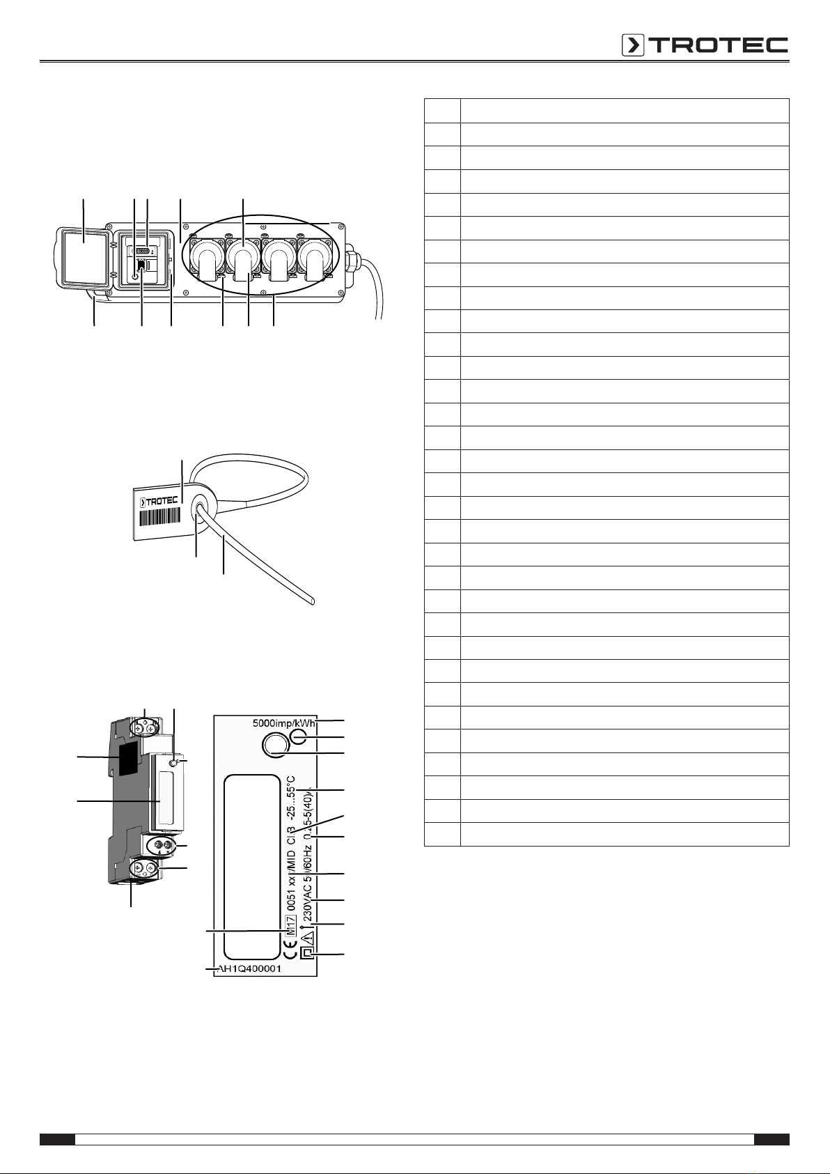
Information about the device
Device description
The device serves for the mobile power supply on varying
application devices. It comes with the following device
characteristics:
• 4safety sockets CEE7/3 with one PlugSafe appliance each
• Solid rubber housing with integrated carrying handle
• Secured beneath a transparent sealing cap that can be
locked optionally
• 1MID-compliant energy meter(kWh)
• 8eyelets
• 1residual current device(RCD) for commercial and
industrial use in wet rooms
The PlugSafe appliance serves for protecting an inserted plug
from unauthorised replacing or swapping and from unauthorised
plugging of an additional consumer to the PV4-MID PS.
For sealing the sockets, use the Trotec pull-up seals (numbered
consecutively). The seals can prevent manipulations. You can
purchase the consecutively numbered pull-up seals under the
articlenumber6.100.002.085 in a pack of10.
The German supervisory authority requires MID-compliant
energy meters for the use of devices in the renovation area or
for drying housings, if the energy consumption is to be recorded
and billed by use of the energy meter. Moreover, it has to be
ensured that the measuring device cannot be manipulated.
Please note that the connected devices that are equipped with
service sockets have to be protected from the unauthorised
connection of additional consumers and from the unauthorised
replacement of a justifiably connected consumer according to
the Measurement and Calibration Act. If required, you can
separately purchase the Plug Safe flange plate for this purpose
under the articlenumber6.100.002.083 in a pack of10. Have
the flange plate mounted by a qualified electrician at the service
socket of your device. You can close the multiple socket outlet
by pulling the seals through the eyelets.