SENKO SG-60 User manual

Solid fuel
COOKERS
SG-60, SG-75 and SG-90
SN-EN-9/16

SENKO cookers SG –
Instruction manual
1
Dear client, thank you for choosing a SENKO cooker!
This product was designed and manufactured to its minutest
details in order to fulfill your every need for functionality and
safety.
This
Instruction manual
will teach you to operate your cooker
properly, so please read the manual carefully before using the
cooker.
Senko management
Symbols used in this
INSTRUCTION MANUAL:
ATTENTION WARNING
SAFETY ADVICE AND RECOMMENDATIONS
SENKO cookers SG –
Instruction manual
2
CONTENTS
1. GENERAL ……………………………………………………………………..4
1.1. FUEL ……………………………………………………………………….6
1.2. FEEDING …………………………………………………………………...6
1.3. CHIMNEY ………………………………………………………………….7
1.3.1. CHIMNEY CAP ………………………………………………………..7
1.3.2. CHIMNEY FUNCTION ………………………………………………….8
1.4. INSULATION ……………………………………………………………..10
2. WARNINGS AND SAFETY …………………………………………………10
3. TECHNICAL FEATURES ……………………………………………………11
4. INSTALLATION ……………………………………………………………..14
4.1. POSITIONING …………………………………………………………….14
4.2. CHIMNEY PREPARATION AND CONTROL ……………………………….16
4.3. CONNECTING TO CHIMNEY ……………………………………………...16
4.4. FRESH AIR VENTS ………………………………………………………..20
4.5. OVEN THERMOMETER …………………………………………………..22
4.6. INSTALLATION TESTING …………………………………………………22
5. HANDLING THE PRODUCT ……………………………………………….23
5.1. DIRECTING THE FLUE GAS ……………………………………………….23
5.2. AIR ADJUSTMENT AND REGULATION …………………………………...24
5.3. FIREBOX GRATE …………………………………………………………25
5.4. FIRING ……………………………………………………………………26
5.4.1. PROCEDURE ………………………………………………………..26
5.4.2. OPTIMUM USE VALUES ……………………………………………...26
5.4.3. ADDING FUEL ………………………………………………………27
5.4.4. FEEDING IN TRANSITION PERIOD …………………………………….28
5.5. OVEN DOOR ……………………………………………………………..28
5.6. FUEL BOX ………………………………………………………………..29
5.7. HEIGHT ADJUSTMENT …………………………………………………...30

SENKO cookers SG –
Instruction manual
3
6. CLEANING …………………………………………………………………..30
6.1. CLEANING THE FLUE GAS CHANNEL …………………………………….31
6.1.1. COOKERS SG-75 and SG-90 …………………………………………..31
6.1.2. COOKER SG-60 ……………………………………………………..32
7. MAINTENANCE …………………………………………………………….33
7.1. OLD COOKER DISPOSAL ………………………………………………...33
7.2. SPARE PARTS …………………………………………………………….33
8. MALFUNCTIONS / CAUSES / SOLUTIONS ……………………………...34
9. TECHNICAL SUPPORT …………………………………………………….35
10. TECHNICAL DATA …………………………………………………………36
11. TERMS OF WARRANTY …………………………………………………...37
WARRANTY ……………………………………………………………………...38
INSTALLATION REPORT ……………………………………………………….39
CE MARKING …………………………………………………………………….40
SENKO cookers SG –
Instruction manual
4
1. GENERAL
Classical solid fuel cookers
E 2560 SG-60
E 2375 L SG-75
E 2375 D SG-75
E 2390 L SG-90
E 2390 D SG-90
are models from the SENKO cookers palette which can accommodate your
needs in the best possible way. Therefore, we ask you to CAREFULLY READ
THESE INSTRUCTIONS, which will help you to achieve the best possible
results already during the initial use.
The manufacturer is not responsible for any consequences (people or
animal injuries or property damages) resulting from failure to comply with
this
Manual.
The cooker is hot during operation and the use of protective
heat insulated gloves is compulsory during handling. Children and infirm
individuals are not allowed to handle the cooker.
The external appearance of the cooker is shown on the first page of this
Manual. Cooker principal parts are made of stainless steel plates and
castings of quality grey cast. The cookers are produced with flue gas
connection point on the left or the right side. When ordering the cooker
or the spare parts, it is necessary to state its full designation, for
example: cooker E 2375 D SG-75; which means that the flue gas connection
is on the right side, if the cooker is observed frontally.
The cookers are manufactured in accordance with the EN 12815
standard and comply with all the requirements set by this standard.
These SENKO cookers are intended for cooking, baking and space
heating!
SENKO cookers SG –
Instruction manual
5
Figure 1
23
22
The cooker is packaged in a EURO pallet. During transport, the cooker
must be properly fastened in order to prevent tumbling or damages. The
standard delivered cooker set consists from:
cooker,
instruction manual,
chimney terminal extension (22),
cooker cleaning tool (23).
CAUTION! The cooker weighs between 130 and 200 kg. Extra caution
is necessary when unloading, transferring, moving and installing the
cooker in order to avoid physical injury.
SENKO cookers SG –
Instruction manual
6
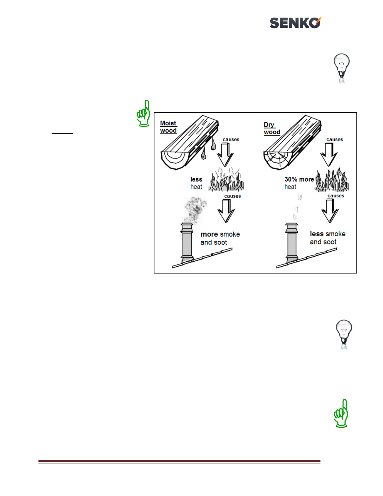
1.1. FUEL
The use of moist and low-calorie wood is not recommended. The wood
moisture must be lesser than 17%. The energy content of moist wood is
low, at approx. 2,3 kWh/kg and it greatly pollutes the door glass, as well as
the chimney and the cooker.
Use only recommended
fuel:
wood: common beech,
common hornbeam, oak,
black locust
air dried for a minimum
of 2 years
relative humidity 15-17%,
energy content at approx.
4,2 kWh/kg
wood briquettes: energy
content at approx. 4,4
kWh/kg
1.2. FEEDING
manually when necessary
we recommend the logs to be of 50 x 50 mm vertical cut, up to 2/3 of
the firebox length
use smaller logs for a more intensive fire, and more massive logs to
maintain fire
the minimum distance between the logs must be 1 cm, the same
distance of 1 cm applies for the briquettes
to maintain constant oven temperature, add smaller quantities of fuel
occasionally approx. 0,5 kg
it is necessary to use protective heat insulated gloves when adding
fuel to the firebox
protective heat insulated gloves must also be used when opening and
closing the oven and firebox door and removing the tray from the oven
and ash box.
SENKO cookers SG –
Instruction manual
7
1.3. CHIMNEY
The cooker is connected to the chimney via 120 mm diameter sliding
rosette. It is necessary to execute the connection of the rosette and the
chimney tightly and impermeably. If the cooker is separated from the
chimney opening (not recommended) the connection is made via standard
120 mm diameter smoke venting pipe –see
chapter 4.3
.
We also advise to equip the chimney with solid material and possible
condensation products collection chamber and to install the chamber in
question beneath the smoke channel inlet, in a manner which allows easy
access and inspection via impermeable door.
IMPORTANT
BEFORE connecting to the chimney it is necessary always to make a
calculation (according to EN 13384 and all other standards for the
chimney dimensioning)!
The chimney has a very important function of the smoke exhaust at
solid fuel heating devices and therefore MUST BE well and properly
dimensioned!
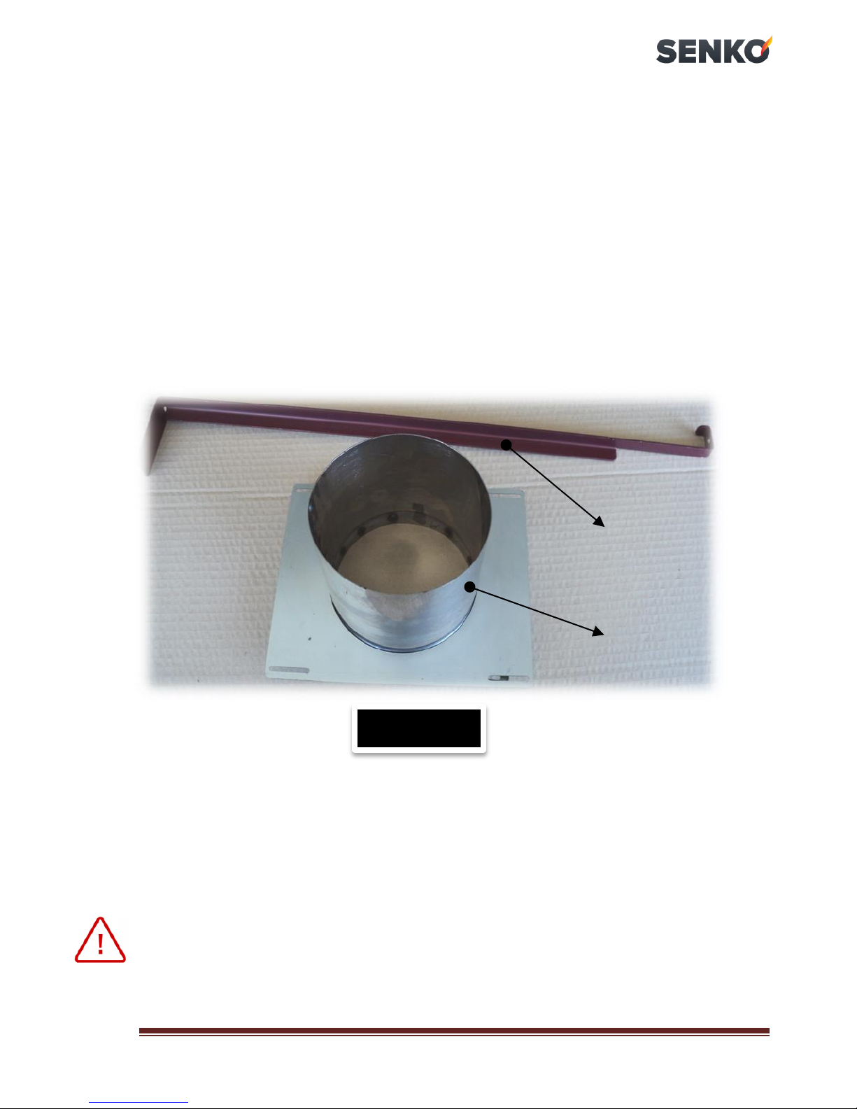
1.3.1. CHIMNEY CAP
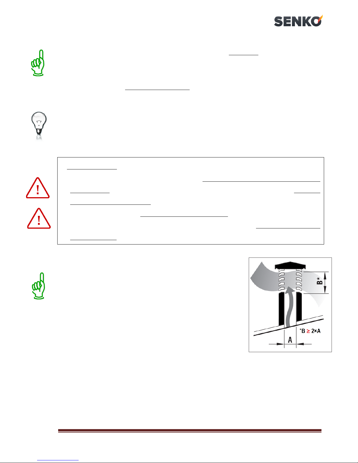
Chimney cap must fulfill the following prerequisites:
identical internal diameter to that of the
chimney,
operational exit cross-section no less than the
double inner diameter of the chimney –see B ≥
2×A in the Figure beside,
constructed to prevent rain, snow, leaves and
other foreign bodies from entering the
chimney,
constructed to enable expulsion of combustion products in case of
wind from any direction and incline,
installed to enable proper dispersion and dilution of combustion
products outside the reflux zone (backflow) because the counter
pressure occurs here. Therefore, it is necessary to adhere to limitations
listed in
Figure 2
,
mechanical appliances for flue gases suction are not allowed.

SENKO cookers SG –
Instruction manual
8
1.3.2. CHIMNEY FUNCTION
Among all the meteorological and geographical factors that influence
the chimney function (rain, fog, snow, insolation period, etc.) the wind is
most certainly the crucial one. Apart from the pressure caused by the
temperature difference between the flue gases and the outer chimney air,
there is another type of pressure –wind dynamic pressure.
Roof
slope
Distance between the
roof ridge and the
chimney
Minimum chimney height
(measured from the roof
surface)
A
, m
H
min, m
15°
< 1,85
0,5 m above the roof ridge
> 1,85
1 m from the roof
30°
< 1,5
0,5 m above the roof ridge
> 1,5
1,3 m from the roof
45°
< 1,3
0,5 m above the roof ridge
> 1,3
2 m from the roof
60°
< 1,2
0,5 m above the roof ridge
> 1,2
2,6 m from the roof
Figure 2
FLAT ROOF
PITCHED ROOF
Z=REFLUX ZONE

SENKO cookers SG –
Instruction manual
9
Ascending wind ALWAYS has the effect of increasing the pressure,
i.e., underpressure (flue draught), provided the chimney is properly
installed. Descending wind ALWAYS has the effect of decreasing the
draught overpressure occurs. Apart from wind direction and velocity,
chimney position in relation to the house roof and surrounding area is also
important (
Figure 3
).
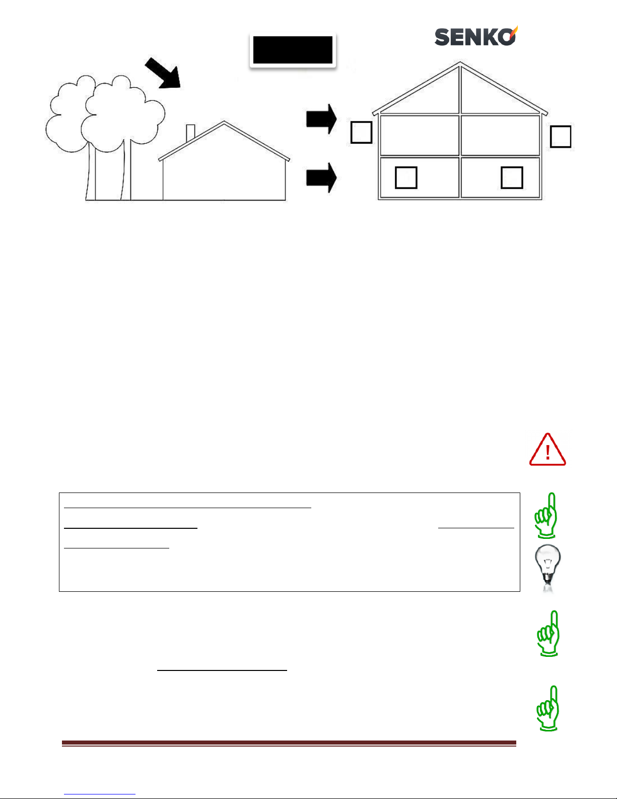
The wind also influences the chimney function indirectly by creating
areas of high (overpressure) and low (underpressure) pressure, both inside
and outside the residential area (
Figure 4
).
Pressure that facilitates chimney function can occur in rooms directly
exposed to the wind (B), but it can also adversely affect the chimney
through external pressure if the chimney is situated on the side exposed to
wind (A). Contrary to that, underpressure can occur in lee rooms (C),
adversely affecting functions of the chimney situated on the opposite side
(D) from the wind direction.
Figure 3
wind
Unfavorable
position
Favorable
position
Horizontal wind 8 m/s
underpressure of
30 Pa
Descending wind under
45
angle and 8 m/s
overpressure of 17 Pa
High (positive)
pressure zone
OVERPRESSURE
Low (negative)
pressure zone
UNDERPRESSURE
Flue
gases
from the
cooker
SENKO cookers SG –
Instruction manual
10
1.4. INSULATION
Cooker is to the outer surfaces isolated with chamotte plates 20 mm
thick. The sides are chamber derived and cooled with the natural air
circulation. The depth of the chamber is 25 mm. Other parts of the cooker
interior are lined with chamotte brick, 40 mm thick.
2. WARNINGS AND SAFETY
When connecting the cooker to the chimney, adhere to national and
European norms and local regulations.
PROCEDURE IN CASE OF CHIMNEY FIRE
In case of chimney fire, close the openings for the air inlet and DON’T open
the firebox door. Extinguish the fire using appropriate fire extinguishers.
NEVER EXTINGUISH A FIRE WITH WATER! In case of fire also call the local
fire department. Comply with local regulations for fire protection!
Prior to use, verify with the local authorized chimney-sweeper whether
the cooker is properly connected to the chimney (the chimney-sweeper
must complete the installation report at the end of this
Manual
).
Special attention must be paid that there is enough air for combustion
being supplied to the room cooker is installed in.
Descending
wind
wind
A
B
C
D
Figure 4
A-B zones in overpressure
C-D zones in underpressure
SENKO cookers SG –
Instruction manual
11
3. TECHNICAL FEATURES
SENKO cookers SG are intended for cooking, baking and household
heating. They are equipped with an oven just like the traditional kitchen
cooker. Cookers are suitable for installation between other kitchen
appliances (with ensuring minimum safety distances –see
chapter 4.1.
)
without heating risks.
They are made of stainless steel plates and castings of quality grey
casts. The cooking plate (1) is made of 8 mm thick steel plate. Cooker
interior is lined with chamotte.
The fuel box (12) is on the frontal side, at the bottom, just above the
manual primary air regulator (10) and the ash box (11). Above them is a
firebox (6) with a grate (16) and the oven (7) with door and thermometer
(18).
Also, the cooker is on the front equipped with two handles, one serves
as a flue gas deflector (14) and is located on the side where is the chimney
connection point, while the other (15) serves as a lever for moving the
firebox grate (16) –
only at cookers SG-75 and SG-90
.
The following figure display the schematic of the cookers and their
accompanying parts.

SENKO cookers SG –
Instruction manual
12
9. Cleaning hatch lid
10. Primary air manual regulator
11. Ash box
12. Fuel box
13. Chimney connection point
14. Flue gas deflector
15. Handle for grate moving
16. Movable grate
17. Oven door glass
18. Oven thermometer
SCHEMATIC DISPLAY FOR COOKERS
SG-75
and
90
THE KEY:
1. Cooking plate
2. Frame
3. Cooker base with screws for
height adjustment
4. Cooker housing
5. Lower door
6. Firebox door
7. Oven with door
8. Oven door hinge
19. Door hinge bolt
20. Firebox door glass
21. Primary air inlet hatch
22. Chimney connection point
extension
23. Cooker cleaning tool
Figure 5a
LEFT COOKER
SG
- view from the side
RIGHT COOKER
SG
- view from the side

SENKO cookers SG –
Instruction manual
13
SCHEMATIC DISPLAY FOR COOKER
SG-60
Figure 5b
THE KEY:
1. Cooking plate
2. Frame
3. Cooker base with screws for height adjustment
4. Cooker housing
6. Firebox door
7. Oven with door
8. Oven door hinge
9. Cleaning hatch lid
10. Primary air manual regulator
11. Ash box
12. Fuel box
13. Chimney connection point
14. Flue gas deflector
16. Firebox grate
17. Oven door glass
18. Oven thermometer
19. Door hinge bolt
20. Firebox door glass
21. Primary air inlet hatch
22. Chimney connection point extension
23. Cooker cleaning tool
COOKER
SG-60
- rear end view
COOKER
SG-60
- view from the side

SENKO cookers SG –
Instruction manual
14
4. INSTALLATION
Once you have removed packaging from the cooker, it is necessary to
make a detailed inspection in order to determine any potential damages
that might have occurred during transport. Nay detected damages must
instantly be reported to the manufacturer.
In places of any connection points on the cooker (chimney, air inlet),
inspection hatches must be installed for system maintenance and
servicing purposes.
4.1. POSITIONING
A spirit level must be used to place the cooker in a horizontal
position with no incline. It is necessary to ensure the minimum distance of
the cooker from any flammable objects; such as wood, chipboard, cork
and similar. If the materials are easily combustible such as PVC,
polyurethane and similar, the necessary safety distances need to be
doubled.
The minimum distance from any flammable surfaces above is 1000 mm
and in front of the cooker is 800 mm, and 200 mm in all other directions.
When mounting the cooker on the floor made from easily combustible
material (wooden floors), the cooker must be mounted on an insulating
non-combustible surface.
A cooker should not be placed in rooms where there are gas stoves
or cookers, and in the bathroom, in buildings intended as laundries or
A
200 mm from the rear wall
B
200 mm from the side wall
C
800 mm from the front side
D
500 mm floor protection
E
300 mm (measured from the
maximum angle of firebox door
opening)
F
Floor protection
G
Radiation area
SENKO
cooker
SENKO cookers SG –
Instruction manual
15
similar. The same applies for rooms or flats with air circulation or hot air
circulation with ventilation systems (air condition, extractor or kitchen
hoods), EXCEPT if such ventilation systems have safety mechanisms, which
sustain the air pressure above 4 Pa in a room, where the cooker is mounted
or in rooms which are in direct contact with exterior air.
It is recommended to place the cooker as close as possible to the
chimney hole, i.e. next to the chimney hole itself in order to avoid using
an additional smoke uptake pipe (
Figure 6a
)!
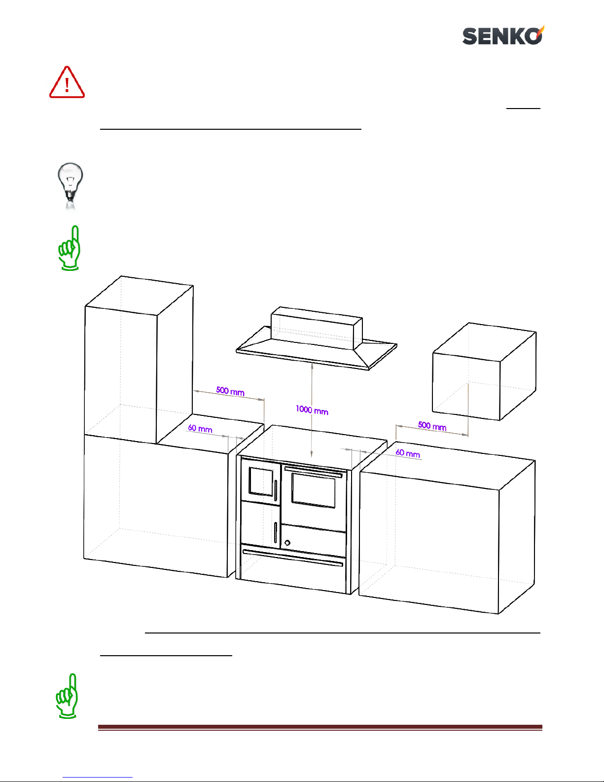
If you want to set the cooker between the kitchen units, it is necessary
to ensure the minimum distances shown in the figure below.
The distance between the cooker and kitchen element is intended for
air circulation (cooling) –see the Figure above.
Here also you should take care on how to ensure access to a cooker for
maintenance and servicing.

SENKO cookers SG –
Instruction manual
16
4.2. CHIMNEY PREPARATION AND CONTROL
Prior to cooker mounting, it is necessary to check the chimney –the
diameter, height, possible clogging or damages. The chimney must be
certified by an authorized local chimney-sweeper. The effective chimney
height must be at least 5 meters from the point of flue gases outlet
(
Figure 6b
).
Flue draught must be within parameters 12 ± 2 Pa.
The chimney must be at least 0,5 meters above the roof ridge (see
Figure 2
). The minimum distance between the two connections on the
same chimney must be 60 cm (
Figure 6d
).
Chimney diameter is chosen according to information provided by the
chimney manufacturer –e.g., for flue draught of 12 Pa, the diameter is
usually 130 mm.
The chimney must be smooth on the inside, well insulated and well
fastened. All cleaning hatches must be well fastened. All gaskets must be
regularly inspected and replaced when necessary.
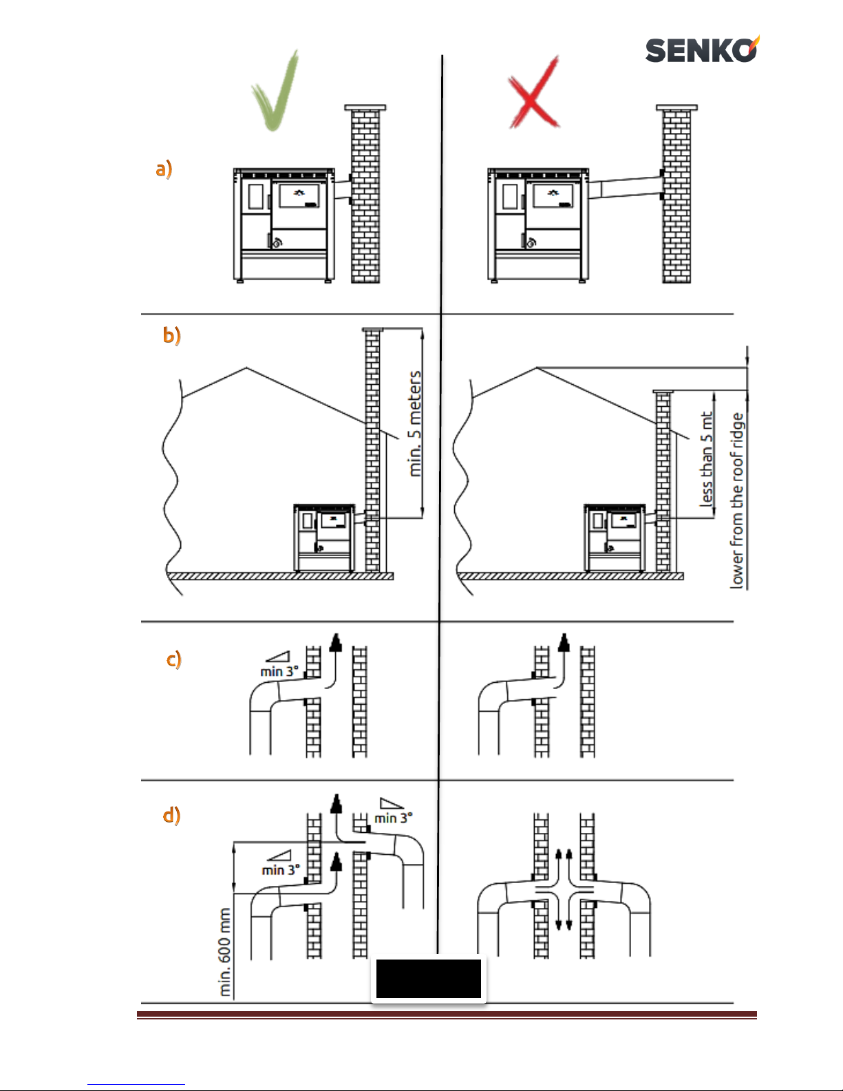
4.3. CONNECTING TO CHIMNEY
When connecting the cooker to the chimney it is necessary to adhere to
local, national and European regulations (norms) –DIN 4705.
It is necessary to ensure that the connection between the cooker and
the chimney is executed tightly and impermeably. Smoke outlet pipe
must have a suitable incline (minimum 3°) in cases where the cooker is
removed from the chimney opening.
Smoke outlet pipe must not penetrate into the chimney clear
opening (
Figure 6c
).
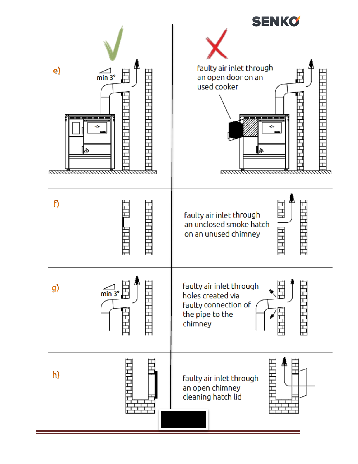
Differences between the proper and improper connection of the cooker
to the chimney are displayed in the following figure.
SENKO cookers SG –
Instruction manual
17
Differences between the proper and improper connection of the cooker to the chimney
Figure 6
SENKO cookers SG –
Instruction manual
18
Differences between the proper and improper connection of the cooker to the chimney
Figure 6
SENKO cookers SG –
Instruction manual
19
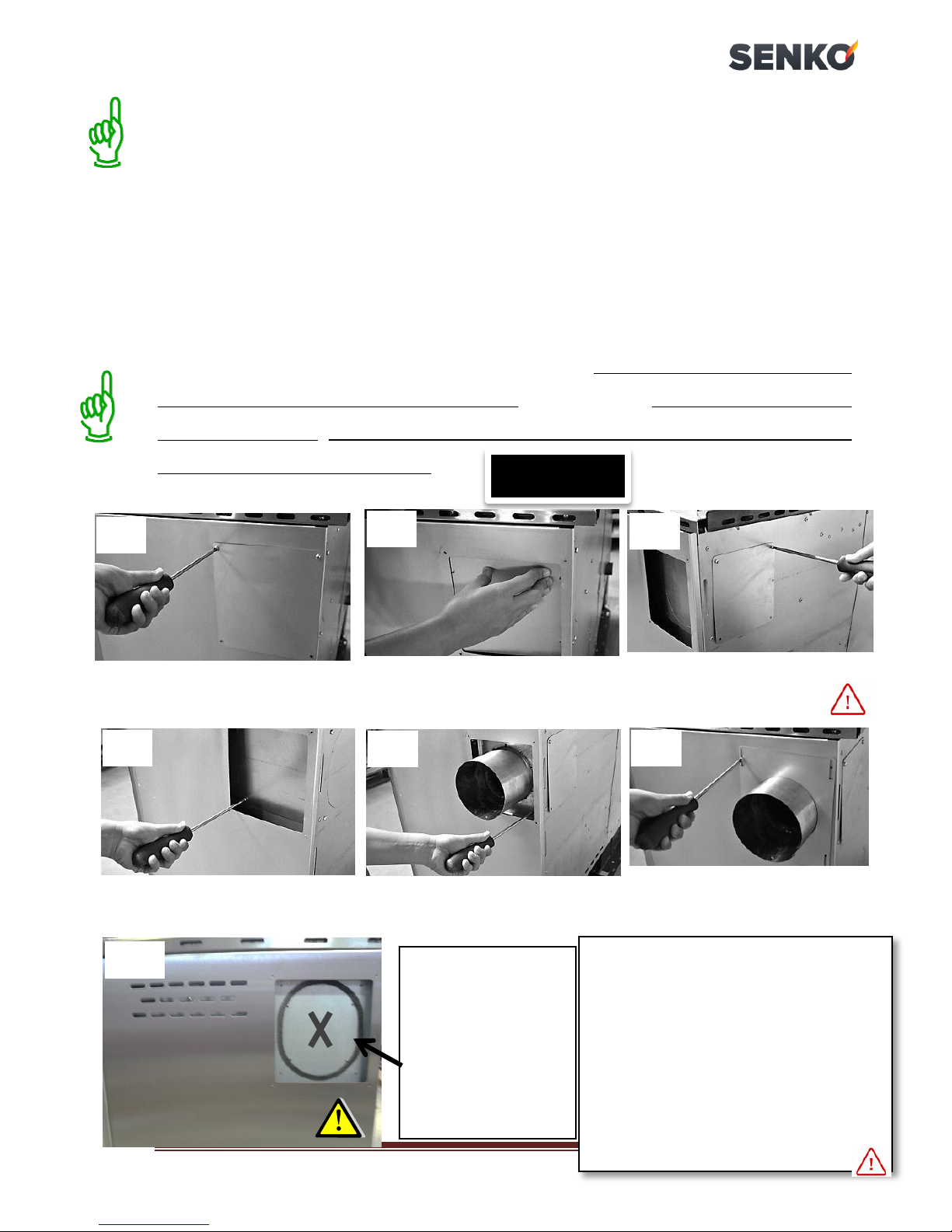
Figure 7
odvijačem skinite
zaštitni poklopac
Remove the external protective
lid with a screwdriver
Remove the sheet beneath the
lid by pressing onto the
weakest juncture
Install the sliding rosette by using
bolts previously used to attach
the inner protective lid
Install the external protective sheet
by using bolts previously used to
attach the external protective lid
Mount the protective lid onto
the remaining chimney
opening!
Remove the internal protective
lid with a screwdriver
When installing the sliding rosette on
the back of the cooker
it is necessary to:
remove the external protective lid with
a screwdriver,
by gently pressing remove the
following lid,
in place of the external lid attach the
sliding rosette with the same screws.
In doing so, you have remain the
external sheet metal of the rosette and
external lid (which are at the beginning
removed from the cooker), as excess.
Connect the cooker to the chimney using a sliding rosette, 120 mm in
diameter. Specially designed sliding rosette enables the adjustment of the
chimney opening in tolerance of 1,5 cm upwards, i.e. downwards.
In case it is necessary to connect the cooker to the chimney with
vertical uninsulated pipe, use the smoke outlet pipe, up to 125 cm
maximum length.
It is not allowed to reduce the prescribed pipe diameters!
If the cooker is further removed from the chimney opening, it is
connected via extension tube and an elbow. The extension smoke inlet
pipe must have an appropriate incline (see
Figure 6
)and must not exceed
100 cm in length. The connection of the chimney and the smoke inlet pipe
must be completely fastened!
1)
2)
3)
4)
5)
6)
Before installing
the sliding rosette,
it is obligatory to
stick the self-
adhesive strip
(provided with your
cooker) on the
inner sheet metal!
5)*
*on some models only
This manual suits for next models
7
Table of contents
Other SENKO Cooker manuals


Popular Cooker manuals by other brands


Falcon
Falcon Toledo TXT110DFSSEU Instructions for use and installation

Tricity Bendix
Tricity Bendix SPLASHBACK SB416 Operating & installation instructions

Commercial CHEF
Commercial CHEF CHC18MB user manual

Smeg
Smeg CX 60 manual

Currys
Currys ESSENTIALS CFTE60W17 instruction manual

Bertazzoni
Bertazzoni AMD6C61BX Installation, maintenance and use instructions


