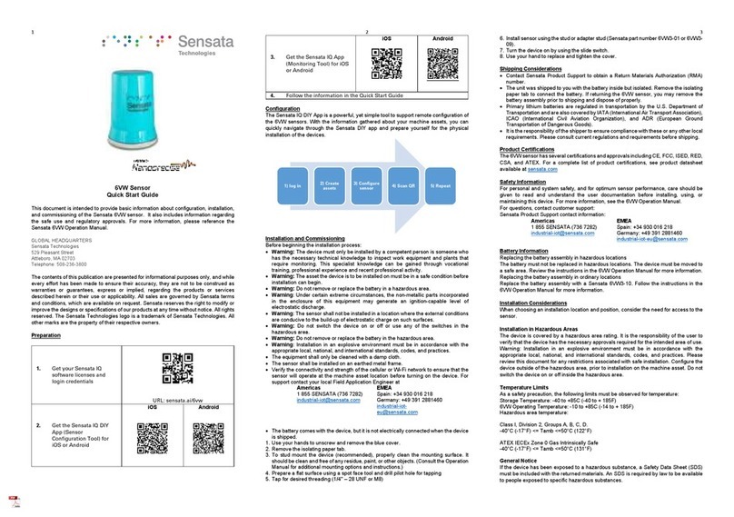
Sensata Nanoprecise 6VW User manual

Copyright © 2022 Sensata Technologies, Inc. Page 1
|MACHINE HEALTH MONITORING (MHM) 6VW SENSOR
OPERATION MANUAL

|6VW SENSOR
OPERATION MANUAL
Copyright © 2022 Sensata Technologies, Inc. Page 2
Copyright © 2022 by Sensata Technologies
All rights reserved. No part of this publication may be reproduced, transmitted, transcribed, or
translated into any language in any form by any means without the written permission of Sensata
Technologies.
Disclaimer
This manual is provided for informational purposes. SENSATA TECHNOLOGIES MAKES NO
WARRANTY OF ANY KIND CONCERNING THIS MATERIAL, INCLUDING, BUT NOT LIMITED TO, THE
IMPLIED WARRANTIES OF MERCHANTABILITY AND FITNESS FOR A PARTICULAR PURPOSE.
Sensata Technologies shall not be liable for errors, omissions, or inconsistencies that may be
contained herein or for incidental or consequential damages in connection with the furnishing,
performance, or use of this material. Information in this document is subject to change and does
not represent a commitment on the part of Sensata Technologies. The information in this
operation manual is not all-inclusive and cannot cover all unique situations.
Where to Get Product Support
Sensata provides several ways to reach your Product Support team to get the answers you need
when you need them:
Americas
1 855 SENSATA (736 7282)
EMEA
Spain: +34 930 016 218
Germany: +49 391 2881460
To search for additional documentation or tools, visit sensata.com/iq

|6VW SENSOR
OPERATION MANUAL
Copyright © 2022 Sensata Technologies, Inc. Page 3
Contents
1GENERAL INFORMATION 6
1.1 Scope 6
1.2 Safety Messages 6
1.3 Considerations 6
1.3.1 General 6
1.3.2 Configuration 7
1.3.3 Installation 7
1.3.4 Battery 8
1.3.5 Environmental 8
1.4 Return of Materials 8
2INTRODUCTION 10
2.1 Overview of Machine Health Monitoring (MHM) 10
2.2 What is Predictive Maintenance (PdM)? 10
2.3 Predictive Maintenance (PdM) Process 11
3PLANNING 12
3.1 Planning for Installation and Commissioning 12
3.1.1 Understanding Your Environment 12
3.1.2 Site Surveys 12
3.1.3 Assessing the Machine Asset 13
3.1.4 Determining the number of sensors needed 13
3.1.5 Cellular/Wi-Fi connection strength 13
3.1.6 Identifying Plant Hierarchy 15
4CONFIGURATION 16
4.1 Sensata DIY App 16
4.1.1 Finding the DIY App and User Credentials 16
4.1.2 Sensata DIY User Tasks and Overview 16
4.1.3 Understanding Asset Layouts 17
5INSTALLATION & COMMISSIONING 18
5.1 Device Handling 18
5.2 Sensor Mounting Types 18
5.2.1 Sensor Stud Mount Installation Method (Permanent Installation) 19
5.2.2 Sensor Magnet + Adhesive Installation Method (Permanent Installation) 20
5.2.3 Sensor Magnet Only Installation Method (Temporary Method) 21
5.2.4 Fin Installation Method 21
5.3 RPM Sensor Installation 22
5.3.1 Needed for Installation 22
5.3.2 Low-Speed RPM Installation Safety Considerations 23

|6VW SENSOR
OPERATION MANUAL
Copyright © 2022 Sensata Technologies, Inc. Page 4
5.3.3 Choosing the right location to install the sensor and the magnet: 23
5.3.4 Sensor Orientation 24
5.4 Powering the 6VW Sensor 24
5.5 6VW Sensor Connection Status to the Cellular Network 24
6CELLULAR AND Wi-FI CONNECTION 26
6.1 Connecting Sensors via Blinkup 26
6.1.1 Blink Up Using Wi-Fi 26
6.1.2 SIM Card Instructions for Cellular Operation 27
7SENSOR BATTERY REPLACEMENT 29
8OPERATION 30
8.1 Sensata IQ Overview 30
8.1.1 Main Page 33
8.1.2 Equipment Main Page 34
8.2 Vibration 34
8.2.1 Vibration RMS 34
8.2.2 Vibration Overall RMS 34
8.2.3 Vibration Peak 35
8.2.4 Vibration Kurtosis 35
8.2.5 Vibration Amplitude (Fault Characterization) 35
8.2.6 Vibration Spectrum 36
8.2.7 Vibration Waveform 36
8.2.8 Vibration Frequency Spectrum Waterfall 37
8.3 Acoustic Emission (Sound) 37
8.3.1 AE RMS 37
8.3.2 AE Frequency Spectrum 37
8.3.3 AE Frequency Spectrum Waterfall 37
8.3.4 AE Time Waveform 38
8.4 Magnetic Flux 38
8.4.1 Flux RMS 38
8.4.2 Flux Frequency Spectrum 38
8.4.3 Flux Time Waveform 38
8.5 Temperature 38
8.6 Humidity 38
8.7 Speed 38
8.8 Upload Speed 39
8.9 Battery 39
8.10 NanoAI Alarm & Adaptive Fault Amplitude Threshold 39
8.11 Sensata IQ Dashboard Terminologies 39
8.12 Health Score & RUL Calculation 42
Notification on Health Status Summary & RUL 43

|6VW SENSOR
OPERATION MANUAL
Copyright © 2022 Sensata Technologies, Inc. Page 5
8.12.1 Algorithm for Self-Adaptive Fault Stage 4 Threshold 44
8.12.2 Notification Details with Different Health Status 44
8.12.3 RUL presentation 45
8.12.4 Notification by NanoAI Alarm 45
8.12.5 Notification by Email Alarm 46
8.13 Sensor Operational Status Notification 47
8.14 Notification on Real-Time Anomaly Detection by Edge Computing 48
8.14.1 Anomaly Detection by Temperature on Edge 50
9TROUBLESHOOTING 51
9.1 Hardware Overview 51
9.1.1 Hardware Troubleshooting 51
9.1.2 Check the Battery 52
9.1.3 Check for damage 53
9.1.4 Verify IR sensor position 53
9.1.5 Ensure eSIM switch 53
9.2 Cellular Connectivity 54
9.2.1 A Board LED Blink Pattern 54
9.2.2 Waiting for Modem 54
9.2.3 Waiting for the SIM 54
9.2.4 Registering with a cell 54
9.2.5 Cell Registration is Denied 54
9.2.6 Connecting via PPP (Point to Point Protocol). 54
9.2.7 Checking PPP connection. 55
9.2.8 B-Board LED Blinking pattern 55
10 SPECIFICATIONS AND REFERENCE DATA 56
10.1 Functional Specifications 56
10.2 Physical Specifications 57
10.3 Performance Specifications 59
11 PRODUCT CERTIFICATIONS 60
11.1 Wireless Certifications 60
11.2 Certifications 61
12 PRODUCT DECLARATIONS 63
12.1 UKCA Mark 63
12.2 CE Mark 63

|6VW SENSOR
OPERATION MANUAL
Copyright © 2022 Sensata Technologies, Inc. Page 6
1 GENERAL INFORMATION
1.1 Scope
This document provides support information for the proper installation, commissioning, and
operation of the Sensata Machine Health Monitoring sensors and the use of the corresponding
Sensata IQ software and applications. It also includes the usage and installation of accessories
provided along with the sensors, which may include SIM (Subscriber Identity Module) cards,
mechanical mounting options, and other useful tools.
1.2 Safety Messages
Instructions in this operation manual may require review and special precautions to ensure the
safety of the personnel performing the operations.
The Sensata 6VW sensor complies with Part 15 of the FCC (Federal Communications Commission)
Rules. Operation is subject to the following conditions:
•This device may not cause harmful interference, this device must accept any interference
received, including interference that may cause undesired operation.
•This device must be installed to ensure a minimum separation of 20 cm (about 7.87 in)
from all persons.
Review the following safety messages before performing an operation preceded by the warning
symbol:
WARNING
Possible danger!
Non-compliance may result in death or serious injury.
Possibilité de danger!
Le non-respect peut entraîner la mort ou des blessures graves.
Explosions could result in death or serious injury:
•Before connecting the sensor in an explosive environment, make sure the instruments
are installed in accordance with applicable field wiring practices.
•Verify that the operating environment of the Sensata 6VW sensor is consistent with the
appropriate hazardous locations' certifications.
1.3 Considerations
1.3.1 General
The Sensata 6VW sensor has different sensing capabilities in the same device. These include
triaxial vibration, acoustic emission, temperature, magnetic flux, and speed detection. The
sensors gather data by converting the physical world into data that is transmitted through Wi-Fi

|6VW SENSOR
OPERATION MANUAL
Copyright © 2022 Sensata Technologies, Inc. Page 7
or cellular networks to the cloud where it is processed, and machine learning algorithms are used
to calculate actionable insights. The display of raw data and insights are sent to a unique URL
known as Sensata IQ. See the following figure to understand the high-level architecture.
1.3.2 Configuration
The sensor can be configured before or after installation, but it is highly recommended that you
configure the sensor before installation using supporting Sensata tools. By fully configuring
before installation, you can save time at the destination and simplify the entire installation and
commissioning process.
Ensure the sensors are installed per applicable field installation practices. Please see the
following sections on installing the sensors for more information.
The 6VW sensors are powered whenever the battery is installed, the isolating paper tab removed,
and the slide switch is in the on position.
1.3.3 Installation
When choosing an installation location and position, provide ample access to the sensor.
The sensor has multiple mounting locations possible. The normal mounting position for a
horizontal asset is in a vertical orientation, perpendicular to the shaft and on the bearing case.

|6VW SENSOR
OPERATION MANUAL
Copyright © 2022 Sensata Technologies, Inc. Page 8
Horizontal mounting is also an option. For more information, see section 5 Installation&
Commissioning.
1.3.4 Battery
The Sensata 6VW sensor uses a battery assembly that includes a Lithium Thionyl Chloride D sizes
battery with a supercapacitor. Off-the-shelf Lithium Thionyl Chloride D batteries are not
recommended. The supercapacitor is an important part of the system and ensures additional
storage capacity when an inrush of current is required to support the modem.
The battery comes with the device, but it is not electrically connected when the device is shipped.
You need to connect the battery by grasping the paper by gently pulling the isolating paper tab
out. You may then turn the device on by using the slide switch.
1.3.5 Environmental
The monitor operates within specifications for ambient temperatures between
–10°C and +85°C (14°F and 185°F).
Please verify that the operating environment of the sensor is consistent with the appropriate
hazardous location certifications.
1.4 Return of Materials
You may need to ship the device to Sensata Technologies for return or replacement in case of
warranty issues. Before shipping, contact Sensata Product Support to obtain a Return Materials
Authorization (RMA) number and receive additional instructions.
Sensata Product Support contact information:
Americas
1 855 SENSATA (736 7282)
EMEA
Spain: +34 930 016 218
Germany: +49 391 2881460
Web: https://www.sensata.com/contact-us

|6VW SENSOR
OPERATION MANUAL
Copyright © 2022 Sensata Technologies, Inc. Page 9
______________________________________________________________________________
Note
If the 6VW sensor has been exposed to hazardous substances, a Material Safety Data Sheet
(MSDS) must be included with the returned materials. An MSDS is required to be available to
people exposed to specific hazardous substances.
Shipping considerations for wireless products (Lithium Batteries)
•The 6VW sensor was shipped to you with the battery inside but with an isolated paper
tab. Remove the tab to connect the battery for proper operation.
•Primary lithium batteries are regulated in transportation by the U.S. Department of
Transportation and are also covered by IATA (International Air Transport Association),
ICAO (International Civil Aviation Organization), and ADR (European Ground
Transportation of Dangerous Goods).
•It is the responsibility of the shipper to ensure compliance with these or any other local
requirements. Please consult current regulations and requirements before shipping.

|6VW SENSOR
OPERATION MANUAL
Copyright © 2022 Sensata Technologies, Inc. Page 10
2 INTRODUCTION
2.1 Overview of Machine Health Monitoring (MHM)
Organizations around the world are seeking ways to maximize the performance of their machine
assets. These organizations are negatively impacted by machine asset downtime, which on
average occurs hundreds of times per year and can cost millions in lost production.
A machine health monitoring solution enables a connection to your current rotational equipment
and provides critical insights that allow you to reduce unplanned downtime, optimize
maintenance strategies and reduce labor expense.
The first step is to use machine health monitoring to address unplanned downtime in machine
assets. This happens at the ground level: on the factory floor where various machine
configurations make up production lines.
Until recently, the most advanced way to prevent unplanned downtime in manufacturing was to
create and use predictive models that track machine data —such as vibration, oil analysis, and
thermography —to predict when machine malfunctions would occur. However, most facilities
do not monitor these machines continuously and in other senses only sporadically. In many
plants, companies assign people resources and create route-based repair initiatives to maintain
machines. Or perhaps they utilize outside contractors to regularly conduct preventive
maintenance readings and assessments. Both approaches incur costs that increase maintenance
budgets. So, to lessen the impact on both the people resources and budget impact, leading
organizations are turning to Predictive Maintenance (PdM) strategies.
2.2 What is Predictive Maintenance (PdM)?
Predictive maintenance (PdM) techniques are designed to help users determine the condition of
machine assets and to provide insights into when maintenance should be performed. The
predictive approach promises significant cost savings over route-based maintenance because
tasks are performed only when needed. It can be regarded as condition-based maintenance
carried out as suggested by insights into the machine asset.
The value of predictive maintenance (PdM) is to allow convenient scheduling of maintenance and
to prevent unplanned downtime. Companies that implement such strategies typically see a fast
return on investment and significant maintenance expenses.
Predictive maintenance differs from preventive maintenance because it relies on the actual
condition of machine assets, rather than average or expected life statistics, to predict when
maintenance will be required. Machine Learning approaches are implemented for the definition
of the actual condition of the machine asset and for forecasting its longevity.

|6VW SENSOR
OPERATION MANUAL
Copyright © 2022 Sensata Technologies, Inc. Page 11
2.3 Predictive Maintenance (PdM) Process
It is Sensata’s primary goal to help your company facilitate a successful Predictive Maintenance
(PdM) implementation. As such, Sensata has identified the critical path shown in the graphic
below. The Sensata PdM solution incorporates leading-edge sensing technology (the 6VW
sensors) and software (Sensata IQ). The buildout of your PdM project will utilize both and you
will engage with each. In the following manual sections, each section header will contain the
highlighted topic in which you will be working. This will be noted by a change in the font color.
Plan
Project Configure
Sensors Install
Sensors Connect
Sensors Operation

|6VW SENSOR
OPERATION MANUAL
Copyright © 2022 Sensata Technologies, Inc. Page 12
3PLANNING
3.1 Planning for Installation and Commissioning
The most important function ensuring the success of your application is planning. Planning helps
us decide how best to use our resources (people, time, money, information, equipment).
3.1.1 Understanding Your Environment
When considering the installation of sensors at your sites or plants, there are several inputs
required that make sensor installation and commissioning easier. For instance, understanding
the safety conditions, operational environments, asset information, network strength at the
potential application point are critical to obtaining the best result. As such it is important to
gather and document for later use, what may be input to the Sensata commissioning tools.
3.1.2 Site Surveys
Site surveys are an important part of a proper application. In specific, the review of the cellular
or Wi-Fi network can speed your results to data and insights from the Sensata solution (6VW and
Sensata IQ software). The site cellular or Wi-Fi networks available may be either strong or weak.
Knowing the strength of your networks will aid in the sensor’s ability to transmit data to the
cloud. Weak networks can cause the sensor to operate sporadically or not at all and thereby limit
the machine asset insights. So, to ensure the performance of the solution, Sensata utilizes some
tactics to support a successful installation. Your assigned Field Application Engineer (FAE) can
provide the details. As a reference point, the following flow chart describes the high-level
process.
By sending a sensor to your site and by directing the sensors to the specific application points,
Sensata personnel can identify the sensor’s ability to send data to the cloud for processing.
Therefore, it is highly recommended that a site survey be conducted before the installation of
OTA Firmware
update to a
sensor
Delivery of asset
to site
Sensor moved to
application point
and powered on
Site Lead and
FAE
collaboration -
data gathered
Repeat as many
times as
necessary
Make
recommendatio
ns and conduct
next steps.
Plan Configure Install Connect Operation

|6VW SENSOR
OPERATION MANUAL
Copyright © 2022 Sensata Technologies, Inc. Page 13
the 6VW sensors. If Sensata FAEs (Field Application Engineer) identify weak Wi-Fi or cellular
networks for the sensor, additional recommendations will be provided that if implemented will
ensure strong connectivity between the 6VW sensor and the cloud.
3.1.3 Assessing the Machine Asset
One of the most important steps in planning for the commissioning of the machine asset is to
ensure that the proper data is gathered. Examples of essential information would be such things
as (but not limited to):
•Variable or constant speed
•RPM
•Bearing type and bearing number
•Electrical line frequency
•Running time
•Asset temperature
Each asset type is unique and therefore may require you to gather specific types of information
as inputs to the Sensata tools (namely the Sensata DIY App). The results and insights
communicated by Sensata IQ are related to the type and quality of machine asset inputs
information entered. If any information is unavailable, it is recommended that you contact the
equipment manufacturer or system integrator.
3.1.4 Determining the number of sensors needed
Frequently asked of Sensata from prospective users is, “How do I know how many sensors I need
to monitor my machine asset?” The general rule is that each rotating machine asset has 2 or
more bearings. Ideally, it is best to have one sensor used with each bearing. However, there are
machine assets where there may be some near each other. In these situations, we recommend
that you work closely with your Sensata FAE to determine the number of sensors required.
3.1.5 Cellular/Wi-Fi connection strength
The 6VW can connect to either LTE-M or Wi-Fi networks. As a default the sensors will be
configured at the time of production for LTE-M connectivity. If you require a Wi-Fi connection,
please review the balance of this section, and then proceed to section 6.2 Connecting Sensors via
Blinkup.
To ensure the sensor will connect version sensor should have following minimum connectivity to
assure proper data upload. Your Sensata FAE (See Product Support contact information on page
2) can assist with the determination of the network strength for each sensing location.
•LTE-M
RSRP: > -110 dBm
RSRQ: > -12 dBm

|6VW SENSOR
OPERATION MANUAL
Copyright © 2022 Sensata Technologies, Inc. Page 14
Below an RSRP of -110 dBm (-111, -112, -113 dBm…) and -12dBm (-13, -14, -15 dBm…), a cellular
signal booster that boosts the LTE-M network will be required for the 6VW sensor to operate
properly.
•GSM/2G
RSSI: > -105 dBm
If the RSSI (Received Signal Strength Indicator) of the 2G signal is below -105dBm (-106, -107, -
108 dBm…), a cellular signal booster that boosts the 2G network will be required for the 6VW
sensor to operate properly.
•Wi-Fi
RSSI: > -75 dBm
Upload speed: > 300 kbps
The 6VW sensor should have following minimum connectivity to assure proper data upload. If
the RSSI of the Wi-Fi signal is below -75 dBm (-78, -79, -80 dBm…), additional steps will need to
be taken to ensure connectivity.
______________________________________________________________________________
Note
Sensors support only 2.4GHz Wi-Fi network bandwidth. The 6VW sensor can determine what
type of security is required, be it WEP, WPA, or WPA2. It supports all these security mechanisms.
The 6VW IS NOT compatible with enterprise-level Wi-Fi authentication, 802.1x, which requires
logging in with a username and password.
The 6VW sensor uses the following ports which should be open for outgoing connection.
______________________________________________________________________________

|6VW SENSOR
OPERATION MANUAL
Copyright © 2022 Sensata Technologies, Inc. Page 15
3.1.6 Identifying Plant Hierarchy
An important part of planning is to consider the needs of the
organization as you create and implement the machine asset
structure. By utilizing the machine asset organizational structure
and/or implementing the structures proposed by Sensata, you can
ensure that all users will follow and understand the format. There
are two structures represented in the Sensata DIY app: Classic Layout
and Machine Layout. The Classic Layout structure has been most
requested of Sensata and therefore is the default, but the Machine
Layout adds a layer of information, which some companies find
helpful. Your decision on this topic is important as the choice of
Classic or Machine Layout only occurs in the Sensata DIY app with the
first sensor deployment. After that, the choice will be fixed in the
layout that you first chose.

|6VW SENSOR
OPERATION MANUAL
Copyright © 2022 Sensata Technologies, Inc. Page 16
4 CONFIGURATION
4.1 Sensata DIY App
The Sensata DIY app is a tool that is used to support sensor configuration to the machine asset.
The DIY app guides the user through the asset management and sensor management
assignments and readies the sensor for installation on the machine asset.
4.1.1 Finding the DIY App and User Credentials
You can find the Sensata IQ DIY app on the Apple App Store for iOS devices or Google Play for
Android devices. Search for “Sensata IQ DIY” with the platform search tools. Install and open the
app. Or you can scan the following QR codes to the respective locations.
iOS App Store
Google Play Store
After Sensata IQ DIY installation, you will need user credentials (username and password) to
continue. There are two ways to get these credentials if you have not already received them, 1)
through your Sensata FAE (See Product Support contact information on page 2) by providing your
full name and email address, or 2) by scanning the QR code on the label on the inside of the box
and by clicking on “Get Credentials”. The adjacent figure provides an overview of the sensor
configuration process.
4.1.2 Sensata IQ DIY User Tasks and Overview
The Sensata IQ DIY App is a powerful, yet simple tool to support remote configuration of the 6VW
sensors. With the information gathered about your machine assets, you can quickly navigate
through the DIY app and prepare yourself for the physical installation of the devices. Below is an
overview of some of the steps required to conduct configuration.
Plan Configure Install Connect Operation

|6VW SENSOR
OPERATION MANUAL
Copyright © 2022 Sensata Technologies, Inc. Page 17
______________________________________________________________________________
Note: If this is your first time through the DIY App, at the home screen please activate the guide
to better understand the functions available to you.
4.1.3 Understanding Asset Layouts
In the Sensata DIY App, there are 2 layouts available –classic or machine layout. On your first
engagement with the DIY App, you will be allowed to select your preferred method for defining
the hierarchy. Many companies choose the classic layout and therefore this is the default, but
you may elect to use the machine layout to provide another layer of information. Either will work
well, but please note that your first selection will lock the layout for all future entries.
1) Use credentials to
log in
2) Use Asset
Management to
create Plant,
Equipment, and
Components
3) Configure the
sensor by answering
questions about the
asset.
4) Scan sensor QR
code and assign
sensors to
components
5) Repeat as many
times as necessary

|6VW SENSOR
OPERATION MANUAL
Copyright © 2022 Sensata Technologies, Inc. Page 18
5 INSTALLATION &
COMMISSIONING
WARNING
Possible danger!
Non-compliance may result in death or serious injury.
Possibilité de danger!
Le non-respect peut entraîner la mort ou des blessures graves.
Sensata recommends that the person(s) installing the Machine Health Monitoring solution be
someone who has a recognized degree, certificate, or professional standing, or demonstration of
related abilities by extensive knowledge, training, and experience.
5.1 Device Handling
Before beginning the installation process:
Verify the connectivity and strength of the cellular or Wi-Fi network to ensure that the
sensor will operate at the machine asset location before turning on the device. For
support with connectivity, please contact your local FAE (See Product Support contact
information on page 2).
CAUTION
Do not drop, hammer, or impact the device housing before, during, or after
installation.
Ne laissez pas tomber, ne martelez pas et ne heurtez pas le boîtier de
l'appareil avant, pendant ou après l'installation.
CAUTION
When installing the device in hazardous locations, ensure that the device is
grounded to the machine case.
Lors de l'installation de l'appareil dans des zones dangereuses, assurez-vous
que l'appareil est mis à la terre sur le boîtier de la machine.
CAUTION
If the equipment is used in a manner not specified by the manufacturer or
contrary to the instructions in this operation manual, the protection
provided by the equipment may be impaired.
Si l'équipement est utilisé d'une manière non spécifiée par le fabricant ou
contraire aux instructions de ce manuel, la protection fournie par
l'équipement peut être altérée.
5.2 Sensor Mounting Types
Different machine asset types require different mounting locations. For any asset type not shown
here, please contact Sensata to recommend mounting locations. In the adjacent image, the most
common mounting locations for this type of device are identified.
______________________________________________________________________________
Plan Configure Install Connect Operation

|6VW SENSOR
OPERATION MANUAL
Copyright © 2022 Sensata Technologies, Inc. Page 19
Note: It is advisable to place a sensor at every location there is a bearing to adequately cover the
assets' potential failure points. Example: On an electric motor, there is a drive end (DE) bearing
and a Non-Drive End (NDE) bearing.
______________________________________________________________________________
There are several possible mounting methods for the device including stud mount, magnet
mounting, or magnet and adhesive mount. The preferred method is to stud mount the device to
the machine asset as it provides the best mechanical coupling approach, which subsequently
improves the frequency response characteristic of the 6VW sensor. A second approach is to
utilize the magnet and adhesive mount which allows for device mounting in just minutes.
WARNING
Possible product damage!
Do not exceed the specified torque when tightening a stud-mounted
device. Overtightening the device will damage the sensing element and
void the manufacturer’s warranty.
Détérioration possible du produit!
Ne pas dépasser le couple spécifié lors du serrage d'un dispositif monté sur
goujon. Un serrage excessif de l'appareil endommagera l'élément de
détection et annulera la garantie du fabricant.
5.2.1 Sensor Stud Mount Installation Method (Permanent Installation)
1. Thoroughly clean the mounting surface. It should be clean and free of any residue, paint,
or other objects.
2. Prepare the flat surface using a spot face tool and drill pilot hole for tapping
______________________________________________________________________________
Note: The spot face tool attaches to a standard electric drill and provides a machined surface
that is at least 1.1 times greater than the diameter of the sensor. The spot face tool also drills a
pilot hole that can then be tapped for a stud-mounted sensor. (“Sensor mounting/attachment
tools and supplies”)
3. Tap for desired threading (1/4'' –28 UNF or M8)
4. Install sensor using the stud or adapter stud (Sensata part #6VW3-01 or 6VW3-09). Both
are available in the sensor packaging.

|6VW SENSOR
OPERATION MANUAL
Copyright © 2022 Sensata Technologies, Inc. Page 20
______________________________________________________________________________
Note: The use of Thread locker Red is recommended to secure the sensor to the stud or
adapter stud.
WARNING
-Possible danger!
Non-compliance may result in death or serious injury. The recommended
magnets have a pull force of 45 lb. and are extraordinarily strong. Handle
with care when working with multiple units or near metal structures.
Possibilité de danger!
Le non-respect peut entraîner la mort ou des blessures graves. Les aimants
recommandés ont une force de traction de 45 lb et sont très puissants.
Manipulez avec précaution lorsque vous travaillez avec plusieurs unités ou
à proximité de structures métalliques.
5.2.2 Sensor Magnet + Adhesive Installation Method (Permanent Installation)
1. Ensure the mounting surface is clean and free from any residue or paint to ensure the
bonding of the adhesive.
2. A smooth, flat mounting surface is desirable and can be achieved by milling or grinding at
the mounting point.
3. Place a small portion of epoxy on the underside of the mounting base (magnet)
4. Firmly press down the housing and magnet to the mounting area to force the adhesive
out from under the mounting base (magnet).
5. Hold the sensor housing onto the surface for at least 60 seconds until the adhesive can
support the weight of the sensor, ensuring the housing does not move or slide on the
adhesive.
6. Allow full cure of the adhesive per the directions of the manufacturer.
Other manuals for Nanoprecise 6VW
3
Table of contents
Other Sensata Accessories manuals

