Sensata IWR USB Series User manual
| IWR-USB SERIES
UTILITY QUICK START GUIDE
Copyright © 2021 Sensata Technologies, Inc. Page 1
|IWR USB Series
UTILITY QUICK START GUIDE
A Quick Start Guide to the IWR USB Utility software, for
Logging and Displaying Data from Wireless Sensors
Whilst every effort has been taken to ensure the accuracy of this document, we accept no responsibility
for damage, injury, loss, or expense resulting from errors or omissions, and reserve the right of
amendment without notice.
Information for users
This equipment has been tested and found to comply with the limits for a Class B device, pursuant to
part 15 of the FCC Rules. These limits are designed to provide reasonable protection against harmful
interference in a residential installation. This equipment generates uses and can radiate radio frequency
energy, and if not installed and used in accordance with the instructions, may cause harmful interference
to radio communications. However, there is no guarantee that interference will not occur in a particular
installation. If this equipment does cause harmful interference to radio or television reception, which
can be determined by turning the equipment off and on, the user is encouraged to try to correct the
interference by one or more of the following measures:
•Reorient or relocate the receiving antenna
•Increase the separation between the equipment and receiver
•Connect the equipment into an outlet on a circuit different from that which the receiver is
connected
•Consult the dealer or an experienced radio/TV technician for help
Caution: To satisfy FCC RF Exposure requirements for mobile and base station transmission
devices, a separation distance of 20cm or more should be maintained between the antenna of
this device and persons during operation. To ensure compliance operation at closer than this
distance is not recommended. The antenna used for this transmitter must not be co-located or
operating in conjunction with any other antenna or transmitter. No other antenna may be used
with this equipment other than the antenna supplied with this equipment.
This document may not be reproduced in any way without the prior written permission of the
company.

| IWR-USB SERIES
UTILITY QUICK START GUIDE
Copyright © 2021 Sensata Technologies, Inc. Page 2
CONTENTS
1Introduction ___________________________________________________________ 3
1.1 Safety Information _________________________________________________________ 3
1.2 Intended Use______________________________________________________________ 3
1.3 Dipswitch Configuration ____________________________________________________ 3
1.4 Software Installation _______________________________________________________ 4
1.5 Compatibility Mode ________________________________________________________ 4
1.6 Running IWR USB_________________________________________________________ 5
2Usage ________________________________________________________________ 5
2.1 Connection setup __________________________________________________________ 5
2.2. Heading Definitions ________________________________________________________ 6
3Data Logging __________________________________________________________ 7
4Graphing______________________________________________________________ 9
5Certifications _________________________________________________________ 12
6Further Information ___________________________________________________ 13

| IWR-USB SERIES
UTILITY QUICK START GUIDE
Copyright © 2021 Sensata Technologies, Inc. Page 3
1 INTRODUCTION
1.1 Safety Information
This manual contains information that must be observed in the interest of your safety
and to avoid damage to assets. Please read this manual before installing and
commissioning the device and keep the manual in an accessible location for all users.
Contains FCC ID: W70MRF24J40MDME
Caution: To satisfy FCC RF Exposure requirements for mobile and base station
transmission devices, a separation distance of 20cm or more should be maintained
between the antenna of this device and persons during operation. To ensure compliance
operation at closer than this distance is not recommended. The antenna used for this
transmitter must not be co-located or operating in conjunction with any other antenna
or transmitter. No other antenna may be used with this equipment other than the PCB
antenna supplied with this equipment.
Please see the Certifications section for more information on RF Exposure
Compliance
1.2 Intended Use
This product is designed for use with an IWR USB, for monitoring and potentially
logging the data produced by wireless sensors connected to the IWR USB. Live data
can also be viewed in a graphical format. Please note that the logging file size is
proportional to the number of channels selected to be logged, so monitoring many
channels for a considerable time could lead to a large log file.
1.3 Dipswitch Configuration
The 10-way Dip Switch is used to configure the RF Network Code on the I
WR-USB.
The RF Network code must be the same as used on the Transmitters.
Switches 1, 2, 3 & 4 select the network code as below
RF NETWORK 1 2 3 4
1 0 0 0 0
2 0 0 0 1
3 0 0 1 0
4 0 0 1 1
5 0 1 0 0
6 0 1 0 1
7 0 1 1 0
8 0 1 1 1
9 1 0 0 0
10 1 0 0 1
11 1 0 1 0
12 1 0 1 1
| IWR-USB SERIES
UTILITY QUICK START GUIDE
Copyright © 2021 Sensata Technologies, Inc. Page 4
13 1 1 0 0
14 1 1 0 1
15 1 1 1 0
16 1 1 1 1
1.4 Software Installation
Download “IWR USB Installer.exe” and run the installer. Follow the simple steps to
install.
1.5 Compatibility Mode
There are some known issues caused by Windows 10 library files. To resolve this,
please enable compatibility mode.
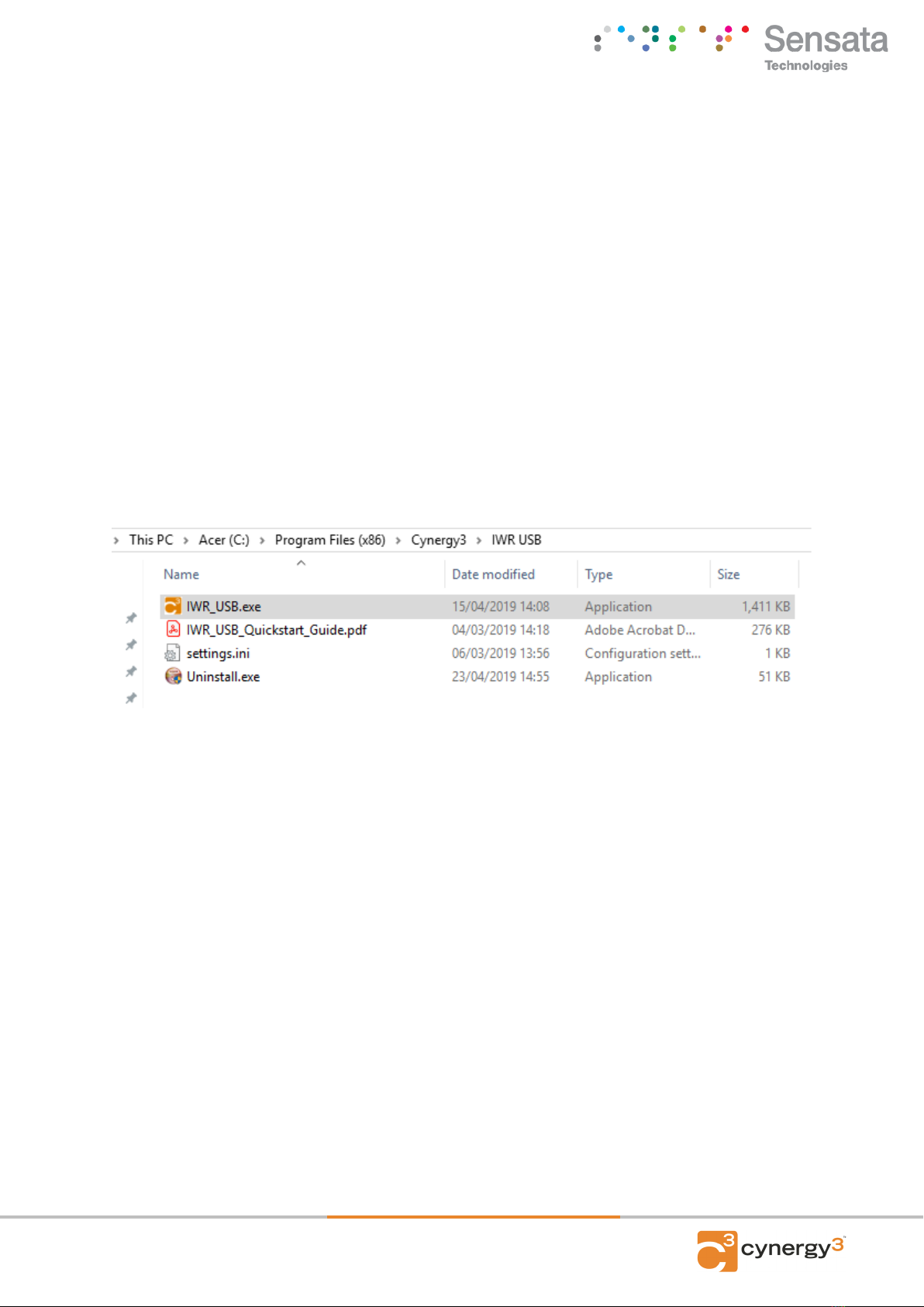
Firstly Navigate to
C:\Program Files (x86)\Cynergy3\IWR USB
Next, right-click on IWR_USB.exe and select properties.
Within properties, select “Compatibility.”

| IWR-USB SERIES
UTILITY QUICK START GUIDE
Copyright © 2021 Sensata Technologies, Inc. Page 5
Under “Compatibility mode” click the tick box and then from the drop-down list
select Windows XP (Service Pack 3). (See above image)
Finally, click OK.
1.6 Running IWR USB
Once completed run “IWR USB.exe,” which can be found on the start menu under
“Cynergy3”, or on your desktop if you selected that option during installation.
2 USAGE
1.1 Connection setup
Firstly, set the Comport in the drop-down list to the Comport assigned to the
serial USB cable you have connected to your IWR-USB. If no comports are
found, try re-connecting the serial USB cable and refresh the Comports via the
“Refresh Comports” button.

| IWR-USB SERIES
UTILITY QUICK START GUIDE
Copyright © 2021 Sensata Technologies, Inc. Page 6
Now to read the devices simply select the Connect button and then click Start.
Note that start will only become enabled to be selected after you have clicked
Connect. Once Start has been pressed the Network value will populate.
The software will then begin reading the device and will populate the
“Engineering Display” tab after completion of its first read cycle.
Heading Definitions
Channel
Channel number of the device reporting.
Serial Number
The serial number of the device reporting.
Scaled Value
The value read after being scaled by the zero and span (see below).
Type
The type of device connected, which is used to define the zero and span values
Span
This is the high scale reading of the sensor connected, defined by the type.
Zero
This is the low scale reading of the sensor connected, defined by the type.
Age
The age of the data when read from the IWR USB,
LQI
| IWR-USB SERIES
UTILITY QUICK START GUIDE
Copyright © 2021 Sensata Technologies, Inc. Page 7
Link Quality Index; a measure of the connection strength between the IWR-USB and
the IWT device
Raw Value
The raw data value before being scaled by the span and zero values.
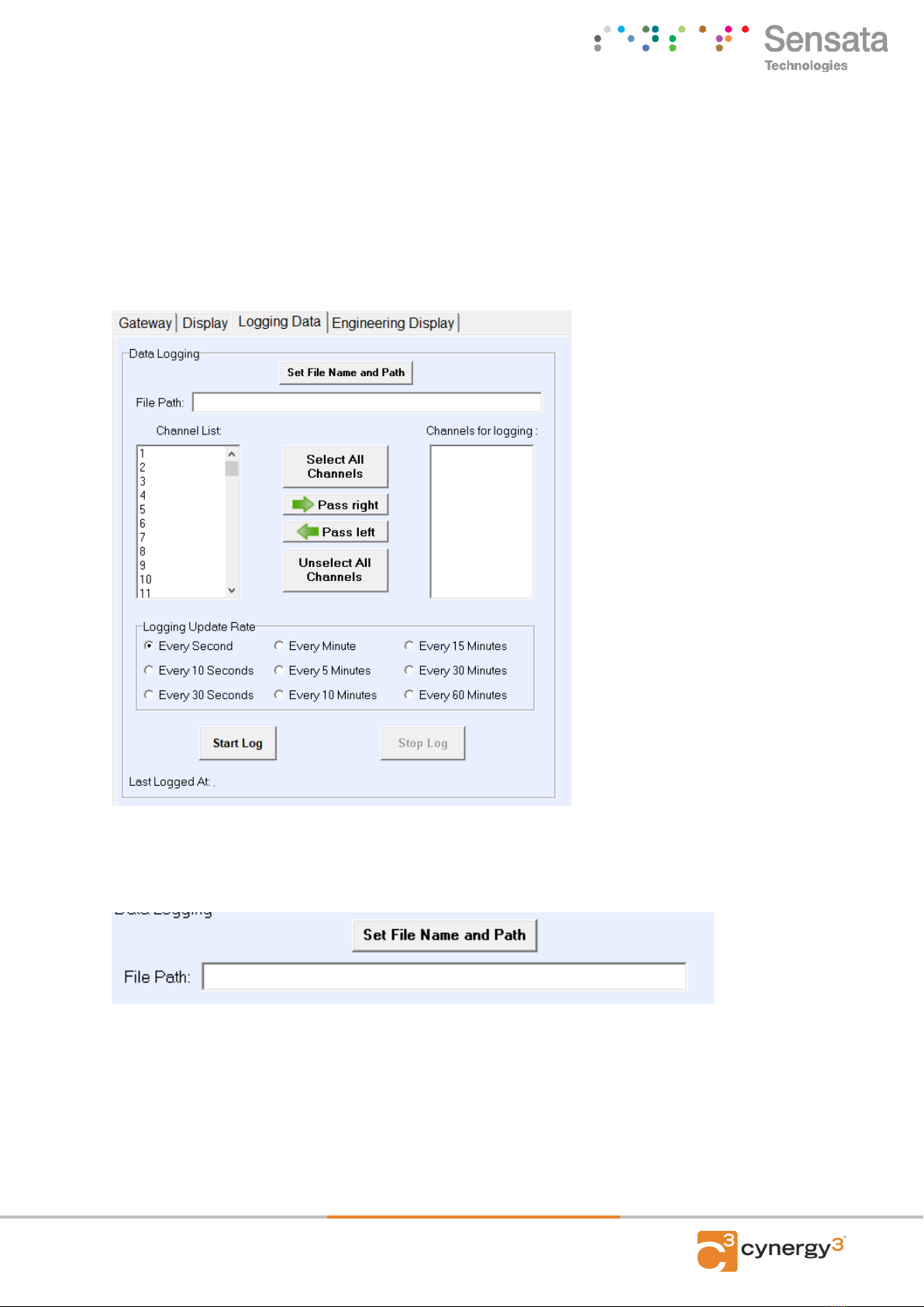
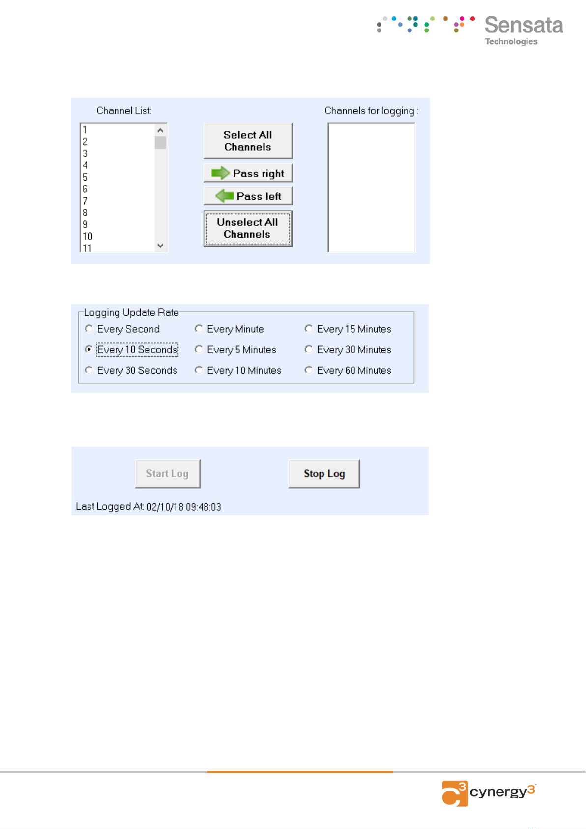
3 DATA LOGGING
To log the data switch to the “Logging Data” tab.
First set the fine name and path using the “Set File Name and Path” button. If you wish to
append to the end of a pre-existing log file, just select the file in the file explorer.
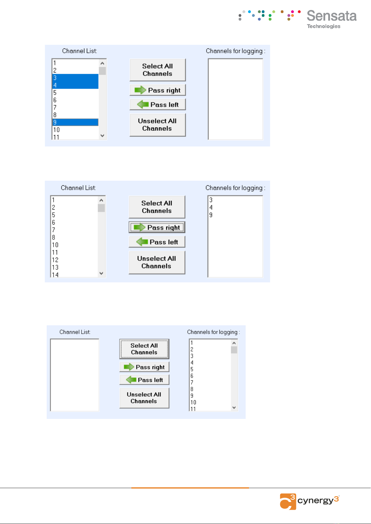
Next, select the channels to log, by clicking on them and then using the “Pass Right” button to
move them into the channels to be logged list. You can select multiple channels at once by
holding CTRL while you click on your desired channels.
| IWR-USB SERIES
UTILITY QUICK START GUIDE
Copyright © 2021 Sensata Technologies, Inc. Page 8
Then pass them right all at once.
You can choose to log every potential channel by using the “Select All Channels” button.
If you no longer want to log a channel, simply pass the channel back to the left. If you wish to
re-select the channels for logging, use the “Unselect All Channels” to reset the selected
channels.
| IWR-USB SERIES
UTILITY QUICK START GUIDE
Copyright © 2021 Sensata Technologies, Inc. Page 9
Next Select your desired logging rate
Finally, click Start. You will see the “last logged at” text is updated as the data is logged at
your desired rate.
Once you have all the data you required logged, simply click Stop Log.
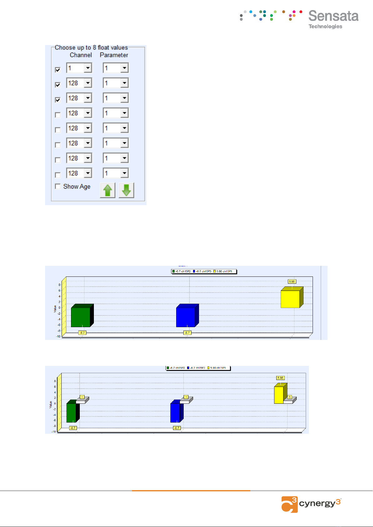
4 GRAPHING
The Graphing tab consists of two graphs, a bar chart, and a line graph. Both graphs will reset
after 15 minutes of either being activated. On the left, you will find a list of channels and
parameters which define the outputs to be displayed on the graph.
| IWR-USB SERIES
UTILITY QUICK START GUIDE
Copyright © 2021 Sensata Technologies, Inc. Page 10
Set the channel and parameter number (parameter number will always be 1 with this version
of the software) of your desired output, and then click the tick box on the left-hand side of the
channel selection to enable that data point on the bar chart.
The age option displays the age of the data in seconds.
The arrows allow you to copy the graph configs in the direction of the arrow e.g. clicking the
arrow pointing down will copy the bar chart configuration to the line graph’s configuration.

| IWR-USB SERIES
UTILITY QUICK START GUIDE
Copyright © 2021 Sensata Technologies, Inc. Page 11
On the line graph, there is a feature allowing you to zoom in or out on the data, or reset the
zoom using the buttons provided. Alternatively, you can “click and drag” to select an area of
the graph to zoom in on the data selected.

| IWR-USB SERIES
UTILITY QUICK START GUIDE
Copyright © 2021 Sensata Technologies, Inc. Page 12
5 CERTIFICATIONS
United States FCC
This equipment has been tested and found to comply with the limits for a Class B device, pursuant to
part 15 of the FCC Rules. These limits are designed to provide reasonable protection against harmful
interference in a residential installation. This equipment generates, uses, and can radiate radio
frequency energy, and if not installed and used in accordance with the instructions, may cause harmful
interference to radio communications. However, there is no guarantee that interference will not occur in
a particular installation. If this equipment does cause harmful interference to radio or television
reception, which can be determined by turning the equipment off and on, the user is encouraged to try
to correct the interference by one or more of the following measures:
•Reorient or relocate the receiving antenna
•Increase the separation between the equipment and receiver
•Connect the equipment into an outlet on a circuit different from that which the receiver is
connected
•Consult the dealer or an experienced radio/TV technician for help
Warning: Changes or modifications not expressly approved by Cynergy3 could void the user’s authority
to operate the equipment.
RF Exposure
Contains FCC ID: W70MRF24J40MDME
In this equipment, the antenna supplied is a PCB antenna and an alternative antenna must not be used.
Caution: To satisfy FCC RF Exposure requirements for mobile and base station transmission devices,
a separation distance of 20cm or more should be maintained between the antenna of this device and
persons during operation. To ensure compliance operation at closer than this distance is not
recommended. The antenna used for this transmitter must not be co-located or operating in conjunction
with any other antenna or transmitter. No other antenna may be used with this equipment other than
the PCB antenna supplied with this equipment.
Canada (IC)
English
This device complies with Industry Canada license-exempt RSS standard(s). Operation is subject to
the following two conditions: (1) this device may not cause interference, and (2) this device must accept
any interference, including interference that may cause undesired operation of the device.
Under Industry Canada regulations, this radio transmitter may only operate using an antenna of the
type and maximum (or lesser) gain approved for the transmitter by Industry Canada. To reduce potential
radio interference to other users, the antenna type and its gain should be so chosen that the equivalent
isotropically radiated power (e.i.r.p.) is not more than that necessary for successful communication.

| IWR-USB SERIES
UTILITY QUICK START GUIDE
Copyright © 2021 Sensata Technologies, Inc. Page 13
Sensata Technologies, Inc. (“Sensata”) data sheets are solely intended to assist designers (“Buyers”) who are developing systems that
incorporate Sensata products (also referred to herein as “components”). Buyer understands and agrees that Buyer remains responsible for
using its independent analysis, evaluation and judgment in designing Buyer’s systems and products. Sensata data sheets have been created
using standard laboratory conditions and engineering practices. Sensata has not conducted any testing other than that specifically described
in the published documentation for a particular data sheet. Sensata may make corrections, enhancements, improvements and other changes
to its data sheets or components without notice.
Buyers are authorized to use Sensata data sheets with the Sensata component(s) identified in each particular data sheet. HOWEVER, NO
OTHER LICENSE, EXPRESS OR IMPLIED, BY ESTOPPEL OR OTHERWISE TO ANY OTHER SENSATA INTELLECTUAL PROPERTY RIGHT, AND
NO LICENSE TO ANY THIRD PARTY TECHNOLOGY OR INTELLECTUAL PROPERTY RIGHT, IS GRANTED HEREIN. SENSATA DATA SHEETS
ARE PROVIDED “AS IS”. SENSATA MAKES NO WARRANTIES OR REPRESENTATIONS WITH REGARD TO THE DATA SHEETS OR USE OF
THE DATA SHEETS, EXPRESS, IMPLIED OR STATUTORY, INCLUDING ACCURACY OR COMPLETENESS. SENSATA DISCLAIMS ANY
WARRANTY OF TITLE AND ANY IMPLIED WARRANTIES OF MERCHANTABILITY, FITNESS FOR A PARTICULAR PURPOSE, QUIET
ENJOYMENT, QUIET POSSESSION, AND NON-INFRINGEMENT OF ANY THIRD PARTY INTELLECTUAL PRO PERTY RIGHTS WITH REGARD
TO SENSATA DATA SHEETS OR USE THEREOF.
All products are sold subject to Sensata’s terms and conditions of sale supplied at www.sensata.com SENSATA ASSUMES NO LIABILITY FOR
APPLICATIONS ASSISTANCE OR THE DESIGN OF BUYERS’ PRODUCTS. BUYER ACKNOWLEDGES AND AGREES THAT IT IS SOLELY
RESPONSIBLE FOR COMPLIANCE WITH ALL LEGAL, REGULATORY AND SAFETY-RELATED REQUIREMENTS CONCERNING ITS PRODUCTS,
AND ANY USE OF SENSATA COMPONENTS IN ITS APPLICATIONS, NOTWITHSTANDING ANY APPLICATIONS-RELATED INFORMATION O R
SUPPORT THAT MAY BE PROVIDED BY SENSATA.
Mailing Address: Sensata Technologies, Inc., 529 Pleasant Street, Attleboro, MA 02703, USA.
CONTACT US
EUROPE
+44 (0)1202 897969
c3w_sales@sensata.com
Cynergy3 Components Ltd.
7 Cobham Road,
Ferndown Industrial Estate,
Wimborne, Dorset,
BH21 7PE, United Kingdom
USA
+1 310 561 8092 / +1 866 258 5057
c3w_sales@sensata.com
French
Le présent appareil est conforme aux CNR d’industrie Canada applicables aux appareils radio exempts
de licence. L’explitation est autorisée aux deux conditions suivantes: (1) l’appareil ne doit pas produire
de brouillage, et (2) l’utilisateur de l’appareil doit accepter tout brouillage, et (2) l’utilisateur de l’appareil
doit accepter tout brouillage radioelectrique subi, même si le brouillage est susceptible d’en
compromettre le fonctionnement.
Conformément à la réglementation d’Industrie Canada, le présent émetteur radio peut fonctionner avec
une antenna d’un type et d’un gain maximal (ou inférieur) approuvé pour l’émetteur par Industrie
Canada. Dans le but de réduire les risques de brouillage radioélectrique à I’intention des autres
utilisateurs, il fait choisir le type d’antenne et son gain de sorte que la puissance isotrope rayonnée
équivalente (p.i.r.e) ne dépasse pas l’intensité nécessaire à l’établissement d’une communication
satisfaisante.
Europe
The MRF24J40MD/ME wireless module used in this equipment has been tested and is in conformity
with the essential requirements and other relevant requirements of the RED Directive 2014/53/EU. That
module is in conformity with the following standards and/or other normative documents:
Certification
Standards
Article
Safety
EN60950-1-2006 / A11:2009 / A1:2010 / A12:2011
/ A2:2013
(3.1(a))
Health
EN 300 328 V2.1.1 / EN 62479:2010
(3.1(a))
EMC
EN 301 489-1 V2.1.1
EN 301 489-1 V2.2.0
EN 301 489-17 V3.1.1
EN 301 489-17 V3.2.0
(3.1(b))
Radio
EN 300 328 V2.1.1
(3.2)
6 FURTHER INFORMATION
For further information please visit
https://cynergy3.co.uk/
Table of contents
Other Sensata Accessories manuals


Popular Accessories manuals by other brands


XD COLLECTION
XD COLLECTION Tusca P322.19 Series manual

Gill
Gill WearDetect 4212-PK-145 quick start guide

Ruian BoYu Automobile Parts
Ruian BoYu Automobile Parts BYMLX26 user manual

Nexmosphere
Nexmosphere X-EYE XY-116 product manual

YOKOGAWA
YOKOGAWA Sushi Sensor technical information

Gared Holdings
Gared Holdings SGRDSPT Series Installation and assembly instructions


