Decagon Devices GS1 User manual

Operator’s Manual
Decagon Devices, Inc.
Version: August 5, 2014 — 08:49:46

GS1
Decagon Devices, Inc.
2365 NE Hopkins Court
Pullman WA 99163
Phone: 509-332-5600
Fax: 509-332-5158
Website: www.decagon.com
Trademarks
“ECH2O” is a registered trademark of Decagon Devices, Inc.
c
2001-2014 Decagon Devices, Inc.
All Rights Reserved
ii

GS1 CONTENTS
Contents
1 Introduction 1
1.1 Warranty ......................... 1
1.2 Seller’s Liability . . . . . . . . . . . . . . . . . . . . . . 2
2 About GS1 3
2.1 Background........................ 3
2.2 Specifications ....................... 3
3 Theory 5
3.1 Volumetric Water Content . . . . . . . . . . . . . . . . 5
3.2 Procedure......................... 5
3.3 Orientation ........................ 6
3.4 Removing the Sensor . . . . . . . . . . . . . . . . . . . 6
4 Connecting Sensors 7
4.1 Wiring........................... 8
5 Collecting Data 10
5.1 Sample Program . . . . . . . . . . . . . . . . . . . . . 10
6 Calibration 13
6.1 Sensor Calibration Values . . . . . . . . . . . . . . . . 13
7 Maintenance and Troubleshooting 16
8 Declaration of Conformity 18
iii

GS1 1 INTRODUCTION
1 Introduction
Thank you for choosing Decagon’s GS1 Volumetric Water Content
sensor. This manual can help you understand the sensor features and
ensure successful sensor operation. We hope you find the contents of
this manual useful in understanding your instrument and maximiz-
ing its benefit to you.
There are several ways to contact Decagon if you ever need assis-
tance with your product, have any questions, or feedback. Decagon
has Customer Service Representatives available to speak with you
Monday through Friday, between 8am and 5pm Pacific time.
Note: If you purchased your sensor through a distributor, please con-
tact them for assistance.
Email:
Phone:
509-332-5600
Fax:
509-332-5158
If contacting us by email or fax, please include as part of your mes-
sage your instrument serial number, your name, address, phone, fax
number, and a description of your problem or question.
Please read these instructions before operating your sensor to en-
sure that it performs to its full potential.
1.1 Warranty
The sensor has a 30-day satisfaction guarantee and a one-year war-
ranty on parts and labor. Your warranty automatically validates
upon receipt of the instrument.
1

1 INTRODUCTION GS1
1.2 Seller’s Liability
Seller warrants new equipment of its own manufacture against de-
fective workmanship and materials for a period of one year from the
date of receipt of equipment.
Note: We do not consider the results of ordinary wear and tear,
neglect, misuse, accident as defects.
The Seller’s liability for defective parts shall in no event exceed the
furnishing of replacement parts “freight on board” the factory where
originally manufactured. Material and equipment covered hereby
which is not manufactured by Seller shall be covered only by the
warranty of its manufacturer. Seller shall not be liable to Buyer for
loss, damage or injuries to persons (including death), or to property
or things of whatsoever kind (including, but not without limitation,
loss of anticipated profits), occasioned by or arising out of the instal-
lation, operation, use, misuse, nonuse, repair, or replacement of said
material and equipment, or out of the use of any method or process
for which the same may be employed. The use of this equipment con-
stitutes Buyer’s acceptance of the terms set forth in this warranty.
There are no understandings, representations, or warranties of any
kind, express, implied, statutory or otherwise (including, but with-
out limitation, the implied warranties of merchantability and fitness
for a particular purpose), not expressly set forth herein.
2

GS1 2 ABOUT GS1
2 About GS1
The GS1 determines volumetric water content (VWC) by measuring
the dieletric constant of the medium using capacitance and frequency
domain technology. The 70 MHz frequency minimizes salinity and
textural effects, making the GS1 accurate in almost any soil or soil-
less medium. It arrives with generic calibrations for mineral soils and
soilless media included in this Operator’s Manual.
The two-prong design and high measurement frequency allows the
GS1 to measure VWC from 0 to 100% (VWC of saturated soils is
generally 40 to 60% depending on the soil type) and allows accurate
measurement of all soils and soilless medias with a wide range of
salinities.
2.1 Background
In 2012, Decagon released our first stainless steel needle sensor, the
GS3. The GS3 measures volumetric water content, temperature,
and electrical conductivity. The sensor has a side-entry cable, which
made it extremely easy to install in a trench application.
At the time, the GS3 was Decagon’s highest priced water content
sensor. However, its rugged design made it one of our most popular
sensors. Our goal in developing the GS1 is to provide customers with
a low-cost sensor that has the durability of the GS3.
2.2 Specifications
Measurement Time: 10 ms (milliseconds)
Accuracy: ±0.03 m3/m3in typical soils, up to 8 dS/m saturation
extract EC.
With soil-specific calibration: ±0.01 to 0.02 m3/m3in any ma-
terial.
Resolution: 0.001 m3/m3VWC in mineral soils
3

2 ABOUT GS1 GS1
Power Requirements: 3.0 VDC to 15 VDC (absolute maximum) @
15 mA
Output: 1,000 to 2,500 mV
Operating Environment: -40 to 50 ◦C1
Range of Measurement: 0 to 100% VWC
Sensor dimensions: 8.9 cm x 1.8 cm x 0.7 cm
Connector Types: 3.5 mm (stereo) plug or stripped & tinned lead
wires (Pigtail)
Cable Length: 5 m standard; custom cable length available upon
request
Data logger Compatibility (not exclusive):
•Decagon: Em50, Em50R, Em50G, Em5b, and ProCheck
•Campbell Scientific: CR10X, CR850, 1000, 3000, etc.
1Sensors can be used at higher temperatures under certain conditions. Please
contact Decagon for assistance.
4

GS1 3 THEORY
3 Theory
3.1 Volumetric Water Content
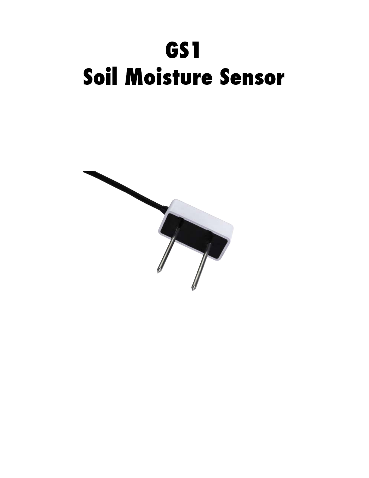
The GS1 sensor uses an electromagnetic field to measure the dielec-
tric permittivity of the surrounding medium. The sensor supplies a
70 MHz oscillating wave to the sensor prongs that charges according
to the dielectric of the material. The stored charge is proportional
to substrate dielectric and substrate volumetric water content. The
GS1 measures the charge and outputs a raw value that strongly cor-
relates to VWC. Decagon has a few helpful reminders to consider
before using your sensor.
•If you are installing sensors in a lightning prone area with
a grounded data logger, please see our Application Note at
www.decagon.com/lightning.
•Decagon advises that you test the sensors with your data log-
ging device and software before going to the field.
Before you select a site for installation, remember that the soil next
to the sensor surface has the strongest influence on its readings. It
is important to avoid air gaps or extremely compact soil around the
sensor, which can skew readings. Do not install the GS1 next to
large metal objects, which can attenuate the sensor electromagnetic
field and distort output readings.
Because the sensors have gaps between their prongs, it is also impor-
tant to consider the size of the media where you insert the sensor. It
is possible to get sticks, bark, roots or other material stuck between
the sensor prongs, which will adversely affect readings. Finally, be
careful when inserting the sensors into dense soil, as the prongs can
bend if you apply excessive force when pushing them into the soil.
3.2 Procedure
Excavate a hole or trench a few centimeters deeper than the sensor
installation depth. At the installation depth, shave off some soil from
the vertical soil face to expos undisturbed soil. Insert the sensor into
5

3 THEORY GS1
the undisturbed soil face until both needles are pushed completely
in the soil face so that the cable is coming towards the soil surface
with no bends. The tip of each prong has been sharpened to make
it easier to push in the sensor. Be careful to avoid the sharp tips.
Back fill the trench taking care to pack the soil back to natural bulk
density around the white PVC portion of the sensor.
3.3 Orientation
You may orient the GS1 in any direction. However, to eliminate cable
strain, orient the sensor vertically so that the cable exit is closest to
the soil surface, and does not need to bend.
3.4 Removing the Sensor
When removing the sensor from the soil, do not pull it out of the
soil by the cable! Doing so may break the internal connections and
make the sensor unusable. Instead, dig down to where the sensor is
located and uninstall horizontally.
6

GS1 4 CONNECTING SENSORS
4 Connecting Sensors
Decagon designed the GS1 sensor for use with our Em50 series data
loggers, the Em5b, or the ProCheck handheld reader. The standard
sensor (with a 3.5 mm “stereo plug” connector) quickly connects to
and is easily configured within a Decagon logger or ProCheck. (Fig-
ure 1)
Figure 1: Stereo Connector
The GS1 sensor incorporates several features that also make it an
excellent sensor for use with third party loggers. Customers may
purchase the sensor with stripped and tinned wires (pigtail) for ter-
minal connections.
The GS1 sensor comes standard with a five meter cable. Customers
may purchase sensors with custom cable lengths for an additional fee
(on a per-foot fee basis). Obtaining custom length cables eliminates
the need for splicing the cable (a possible failure point).
Connecting to an Em50/Em50R Logger
Decagon designed the GS1 to work specifically with the Em50 and
Em5b data loggers. Simply plug the 3.5 mm stereo plug connector
directly into one of the five sensor ports. Next, configure the logger
port for the GS1 and set the measurement interval.
Connecting to ECH2O Utility
Configure your Decagon data loggers using either ECH2O Utility
7

4 CONNECTING SENSORS GS1
or DataTrac 3. Before trying to configure your logger, please check
your software version to ensure it will support the GS1. To update
your software to the latest version, please visit Decagon’s software
download site at www.decagon.com/support.
The following software support the GS1 sensor:
•ECH2O Utility 1.12 or greater
•ECH2O DataTrac 3 or greater
Note: You must use the ECH2O Utility, DataTrac 3 or a terminal
program on your computer to download data from the logger to your
computer.
4.1 Wiring
Connecting to a non-Decagon Logger
Customers may purchase GS1 sensors for use with non-Decagon data
loggers. These sensors typically come configured with stripped and
tinned (pigtail) lead wires for use with screw terminals. Refer to
your distinct logger manual for details on wiring.
Figure 2: Pigtail End Wiring
Pigtail End Wiring
Connect the wires to the data logger as Figure 3 shows, with the
supply wire (white) connected to the excitation, the analog out wire
(red) to a analog input, the bare ground wire to ground as illustrated
in Figure 3.
8

GS1 4 CONNECTING SENSORS
Note: The acceptable range of excitation voltages is from 3.6 to 15
VDC. If you wish to read your Decagon sensor with the Campbell
Scientific Data Loggers, you will need to power the sensors off of the
switched 12 V port.
If your GS1 is equipped with the standard 3.5 mm plug and you
want to connect it to a non-Decagon data logger, you have two op-
tions. First, you can clip off the plug on the sensor cable, strip and
tin the wires, and wire it directly into the data logger. This has
the advantage of creating a direct connection with no chance of the
sensor becoming unplugged; however, it cannot be easily used in the
future with a Decagon readout unit or data logger.
The other option is to obtain an adapter cable from Decagon. The
3-wire sensor adapter cable has a connector for the sensor jack on
one end, and three wires on the other end for connection to a data
logger (this type of wire is often referred to as a “pigtail adapter”).
Both the stripped and tinned adapter cable wires have the same ter-
mination as seen above; the white wire is excitation, red is output,
and the bare wire is ground.
Figure 3: Connections
9

5 COLLECTING DATA GS1
5 Collecting Data
5.1 Sample Program
The following programs are examples that can be used with data
Campbell Scientific data loggers. The first program is for CR3000
data logger, but can easily be adapted for other “CRBasic” type
loggers. The second program is for a CR10X data logger, but can
be easily adapted to other “Edlog” type loggers. The GS1 needs
3.6 to 15 V DC excitation and therefore cannot be excited with the
2.5 V excitation port of many Campbell Scientific data loggers. We
recommend using the switched 12 V or CAO port to excite the GS1.
CR Basic Type Data Logger
’CR3000 Series Datalogger
’date: 7/7/2014
’program author: Kahlin Wacker
’program to read one Decagon GS1 sensor
’ right click on commands for more info.
’wiring
’white - SW - 12 1
’red - SE CH1
’bare gnd
Public GSonemV, VWC ’ variables
DataTable (Table1,1,-1) ’ the data table logs every 60 minutes an average of the output
DataInterval (0,60,Min,10)
Average (1,VWC,FP2,False)
EndTable
BeginProg
Scan(10,Sec,0,0) ’ interval between program runs
SW12(1,1)’ turn on the 12 volt power to the sensor
VoltSe (GSonemV,1,mV5000,21,1,10000,_60Hz,1.0,0)
’read the voltage from the sensor
SW12 (1,0) ’ turn off the 12 volt power to the sensor
VWC = 0.000494 * GSonemV - 0.554 ’mineral soil calibration
CallTable Table1 ’ write data to data table
10

GS1 5 COLLECTING DATA
NextScan
Endprog
Edlog Type Data Logger
;{CR10X}
;
;program to read GS1 sensor with CR10X
;
;wiring:
;Jumper from C1 to SW 12V CTRL - C1
;is used to turn on the switched 12V port
;GS1 white - excitation - SW 12V
;GS1 red - Vout - SE CH1
;GS1 bare - gnd - G or AG
*Table 1 Program
01: 10.0000 Execution Interval (seconds)
;set C1 high to pull SW 12 port high
;
1: Do (P86)
1: 41 Set Port 1 High
2: Excite-Delay (SE) (P4)
1: 1 Reps
2: 5 2500 mV Slow Range
3: 1 SE Channel
4: 1 Excite all reps w/Exchan 1
5: 1 Delay (0.01 sec units)
6: 0 mV Excitation
7: 2 Loc [ VWC ]
8: .000494 Multiplier
9: -0.554 Offset
;turn off excitation
3: Do (P86)
11

5 COLLECTING DATA GS1
1: 51 Set Port 1 Low
4: If time is (P92)
1: 0000 Minutes (Seconds --) into a
2: 60 Interval (same units as above)
3: 10 Set Output Flag High (Flag 0)
5: Real Time (P77)
1: 1110 Year,Day,Hour/Minute (midnight = 0000)
6: Average (P71)
1: 1 Reps
2: 2 Loc [ VWC ]
*Table 2 Program
02: 0.0000 Execution Interval (seconds)
*Table 3 Subroutines
End Program
12

GS1 6 CALIBRATION
6 Calibration
Decagon’s ECH2O Utility and DataTrac3 automatically apply fac-
tory calibrations to the sensor output data. However, this general
calibration may not be applicable for all soil types. For added accu-
racy we encourage our customers to perform soil-specific calibrations.
Which calibration equation you use depends on where you use it.
If you use it with sensors connected to a non-Decagon data logger
you will need to use the mV calibration. If you use any Decagon soft-
ware (DataTrac3, ECH2O Utility, etc.) or the user calibration menu
in the ProCheck, you must use the RAW calibration. The difference
between the two is the slope constant. To increase the resolution of
the sensor output, Decagon uses all available increments of the 12-bit
number (value of 4096) where the measurement is stored.
6.1 Sensor Calibration Values
Following is a list of the both the millivolt and RAW calibration
values for the GS1, where Θ is the volumetric water content, mV is
the millivolt output of the sensor, and where RAW is the raw sensor
output, when you read the sensor with a Decagon logger.
The GS1 is not sensitive to variation in texture and electrical conduc-
tivity because it runs at a high measurement frequency. Therefore,
its general calibration equation should apply for most mineral soils
up to 8 dS/m saturation extract. Its calibration equations are shown
below for mineral soil and soilless growing media (potting soil, per-
lite, peat moss). However, for added accuracy we encourage our
customers to perform soil-specific calibrations.
Mineral Soils
According to our tests, a single calibration equation will generally
suffice for most mineral soil types with electrical conductivities from
0.1 dS/m to 8 dS/m saturation extract. Volumetric water content
13

6 CALIBRATION GS1
(Θ) is given by:
Θ=3.62 ∗10−4∗RAW −0.554 (1)
where RAW is the output from the Decagon data logger. If you are
using a non-Decagon data logger, VWC is given by:
Θ=4.94 ∗10−4∗mV −0.554 (2)
where mV is the output of the sensor when excited with 3.6 to 15
V. Please note that the equation will reach a maximum at ˜60%
volumetric water content (VWC) in pure water. To display data on
a scale from 0 to 100%, VWC should be modeled with a quadratic
equation (which would result in a 100% VWC in water), but a linear
equation fits the mineral soil VWC range as well as the quadratic,
and linear equations are easier to deal with, especially since mineral
soil typically saturates at ˜40 to 50% VWC.
Soilless Growing Media
The GS1 has been calibrated in media types including potting soil,
perlite and peat. The goal of these calibrations is to create a generic
calibration equation that works in all types of each substrate, with
an accuracy of better that ±5% volumetric water content (VWC).
If you need more accuracy, you can perform a media specific cali-
bration to get the accuracy down to ±1 to 2%. It is interesting to
note the main difference between the calibrations is caused by the
high air volume in the organic soils that lowers the starting (dry me-
dia) output of the sensor. For more information on how to calibrate
your probes, please see http://www.decagon.com/support. Decagon
also has a calibration service, where we perform the calibration for
a standard fee. Contact Decagon for more information about this
calibration service.
The calibration for several potting soils, perlite, and peat moss at
salinities ranging from 0 to >4 dS/m is given:
Θ=4.33 ∗10−4∗RAW −0.611 (3)
for a Decagon data logger or
Θ=5.91 ∗10−4∗mV −0.611 (4)
14

GS1 6 CALIBRATION
for a data logger with 3.6 to 15 V excitation.
15

7 MAINTENANCE AND TROUBLESHOOTING GS1
7 Maintenance and Troubleshooting
If you encounter problems with the GS1, they most likely will mani-
fest themselves in the form of incorrect or erroneous readings. Before
contacting Decagon about the sensor, do the following:
•Check to make sure the connections to the data logger are both
correct and secure.
•Ensure that your data logger batteries are not dead or weak-
ened.
If you continue to encounter problems, please contact Decagon
1. PROBLEM:
Sensor not responding.
SOLUTION:
•Check power to the sensors
•Check sensor cable and 3.5 mm plug integrity
•Check data logger wiring to ensure White - 12 V supply, Red
- Analog In, Bare - Ground
2. PROBLEM
Sensor reading to low.
SOLUTION:
•Check for air gaps around sensor needles. These could be pro-
duced below the surface of the substrate when the needle con-
tacts a large piece of material and pushes them out of the way.
•Ensure the calibration equation you use is appropriate for your
media type. There are significant differences between substrate
16

GS1 7 MAINTENANCE AND TROUBLESHOOTING
calibrations so be sure to use the one specific to your substrate.
3. PROBLEM
Sensor readings are too high.
SOLUTION:
•Check to make sure that the soil was not packed excessively
during sensor installation. Higher density can cause elevated
sensor readings.
•Ensure the calibration equation you are using is appropriate
for your media type. There are significant differences between
substrate calibrations so be sure to use the one specific to your
substrate.
17
Table of contents
Other Decagon Devices Accessories manuals

Decagon Devices
Decagon Devices EC-20 User manual

Decagon Devices
Decagon Devices VP-4 User manual

Decagon Devices
Decagon Devices MAS-1 User manual

Decagon Devices
Decagon Devices 5TE User manual

Decagon Devices
Decagon Devices GS3 User manual

Decagon Devices
Decagon Devices EC-5 User manual

Decagon Devices
Decagon Devices 10HS User manual

Decagon Devices
Decagon Devices VP-3 User manual

Decagon Devices
Decagon Devices ECH2O EA-10 Assembly Instructions

Decagon Devices
Decagon Devices MAS-1 User manual