Sensata Dimensions ADI-24J11 User manual

1
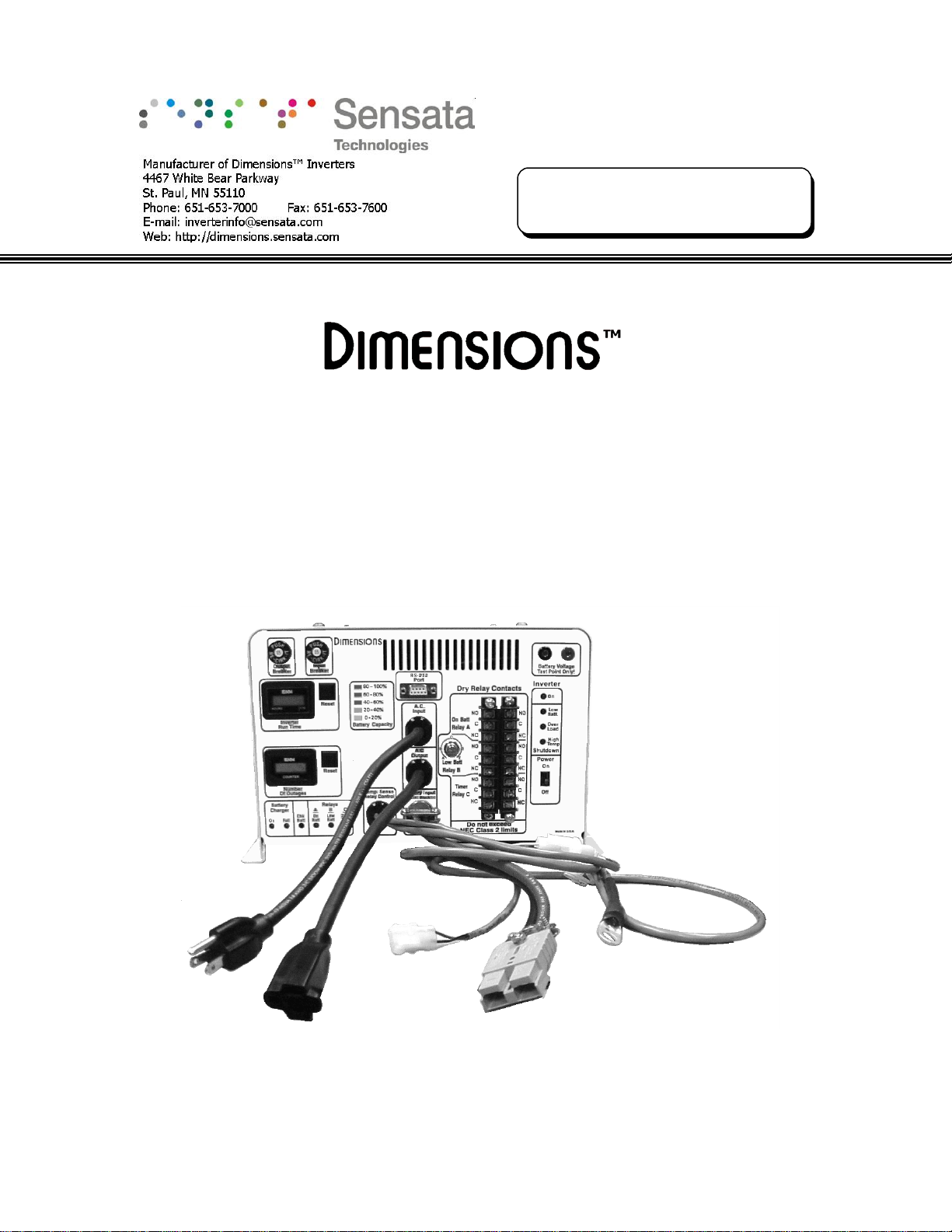
LED Signal Battery Backup System
Installation, Operation and Maintenance Manual
ADI-24J11
Form: 121984D
August 2008

2
Table of Contents
Section Description Page
1.0 Safety Instructions …………………………………………………….. 3
1.1 Warning Symbols ……………………………………………………………………….. 3
1.2 Battery backup System Precautions ……………………………………………… 3
1.3 Battery Precaution ……………………………………………………………………… 3
2.0 Specifications ……………………………………………………………. 4
3.0 System Physical Description …………………………..…………….. 5
3.1 BBS Physical Description ……………………………………………………………… 5
3.2 CMBPS-30ATR 511016-2 (Enclosed case) ……………………………………… 7
3.3 CMBPS-30ATR 511016-1 (Open back panel) …………………………………. 7
4.0 Installation ……………………………………………………………….. 8
4.1 BBS Components ……………………………………………………………….………. 8
4.2 Recommended Useful Tools for Installation …………………………………… 8
4.3 Mounting the BBS ………………………………………………………………………. 9
4.4 Wiring the BBS …………………………………………………………………………… 13
4.5 Dry-Relay Contact Wiring ……………………………………………………………. 15
5.0 Adjustments ……………………………………………………………… 17
5.1 Remaining Battery Capacity Adjustment ……………………………………….. 17
6.0 Communications ………………………………………………………… 19
6.1 Connecting the RS232 Port ………………………………………………………….. 19
6.2 Terminal Setup …………………………………………………………………………… 19
6.3 Using the BBS Communication Interface ………………………………………. 22
7.0 Theory of Operation ……………………………………………………. 24
7.1 System Description …………………………………………………………………….. 24
7.2 Startup Procedure ………………………………………………………………………. 27
8.0 Maintenance & Troubleshooting ….………………………………… 28
8.1 Preventive Maintenance ………………………………………………………………. 28
8.2 Trouble Analysis …………………………………………………………………………. 29
9.0 Parts List ………………………………………………………………….. 32
10.0 Electrical Interconnection ……………………………………………. 33
11.0 Limited Warranty ……………………………………………………….. 34

3
1 Safety Instructions
Important: Read this manual before installation, it contains important safety,
installation, and operating instructions. Save this manual and keep it in a safe place.
1.1 Warning and Danger Symbols:
To reduce the risk of electrical shock and to ensure the safe operation of your
Dimensions power inverter, the following symbols are used throughout the manual.
ATTENTION:
Important operating instructions.
Follow them closely.
DANGER:
Risk of personal harm and/or
electrocution exists in this area.
Use extreme caution.
1.2 Battery Backup System (BBS) Precautions:
•BBS produce hazardous voltages. To avoid risk of harm or fire, the unit must be
properly installed.
•There are no user serviceable parts inside, do not remove the cover.
•The BBS should not be mounted in a location that may be exposed to rain or spray.
•The BBS should not be installed in a zero clearance enclosure.
•Damage to the BBS will occur if correct polarity is not observed when installing the
DC input cables.
•Damage to the BBS will occur if an external AC power source is applied to the
inverter’s AC hardwire output.
•The BBS contains a circuit breaker and capacitor that may produce a spark. Do not
mount in a confined battery or gas compartment.
•Make sure the BBS is turned OFF during installation.
1.3 Battery Precautions:
•Working in the vicinity of lead-acid batteries is dangerous. There is a risk of acid
exposure.
•Batteries generate explosive gases during operation.
•There is risk of high current discharge from shorting a battery that can cause fire
and explosion. Use insulated tools during installation.
•Remove all rings, watches, jewelry or other conductive items before working near
the batteries.
•Inspect the batteries once a year for cracks, leaks or swelling.
•Dispose of the batteries according to local regulations. Do not incinerate batteries;
risk of explosion exists.

4
2 Specifications
Other Design Features:
•Thermally-controlled cooling fan
•Automatic utility line power bypass when utility line volta
g
e is
outside the range of 100 to 130 VAC ± 2 VAC
•Automatic inverter mode dropout when utility line power has
been restored above 105 VAC ± 2 VAC for more than 30
seconds
•Li
g
htnin
g
sur
g
e protection compliant with IEEE 587/ANSI
C.62.41
•Completely connectorized system
•LED for Inverter Power, Low Battery, High Temp, & Overload
•LED for Battery Charger On & Full plus Check Batteries
•LED Battery Voltage Indicator & Voltage Test Points
•LED for Relay A (On Batt), Relay B (Low Batt), and Relay C (2
hour Time)
•Two terminal blocks provide access to BBS Form C dry relay
contacts
•Low Batt voltage threshold (Relay B) is adjustable
•Inverter Run Time Meter w/reset
•Inverter Event Counter Meter w/reset
Unit Protection:
•Automatic electronic short circuit/overload
protection
•Automatic over temperature shutdown
•Input and Output circuit breakers
Battery Protection:
•Automatic low battery shutdown at 21 VDC
•In-line battery cable fuse
•Remote temperature sense cable
•
T
emperature compensated battery char
g
in
g
system - shuts off over 50°C (122°F)
Communication:
•RS232 Communication port provides local
pro
g
rammin
g
, system alarms and download o
f
event buffer via windows based PC.
BBS MODEL NUMBER: ADI-24J11 LED Status light and wiring connectors at front
Output Power (Watts Continuous) 1,100 @ 25°C (77°F), 700 @ 74°C (165°F)
Output Current (Amps AC) Up to 9
Peak Output (Amps AC) 37
Input Current (Amps DC) Up to 55
Weight (Lbs.) 41
Dimensions (WxDxH) (inches) 12½ x 13 x 8
BATTERY CHARGER Built-in
Output Voltage (Volts DC) Regulated and temperature compensated end of charge
at 27.6
Output Current (Amps DC) Up to 13
Input Current (Amps AC) Up to 7
TRANSFER RELAY Built-in
Current Rating (Amps AC) 15
Transfer Time (milliseconds) 40 typical
Output Voltage: 120 VAC regulated (110 to 125VAC)
Output Frequency: 60 Hz ± 0.05%
Output Waveform: Pure sine wave, less than 3% THD
Input Voltage: (VDC) 21 to 28
Operating Temperature: -37° to 74° C (-35° to 165° F)
Efficiency: Up to 85%
•Usage: All NEMA traffic equipment within the inverter’s power rating.
•Warranty: Two year parts and factory labor with Advance Replacement Program
ADI-24J11

5
System Physical Description Section 3
3.1 BBS Physical Description
FIGURE 1: BBS Module model ADI-24J11 physical description front and rear view
17
1
15
2
3
2324252627
14
13
4
5
6
910 1211
7 8
16
18
19
20
21
22

6
(1) Input Breaker: Trips to protect utility power from a BBS short circuit.
(2) Output Breaker: Trips to protect the BBS from a load short circuit.
(3) Inverter Run Time Meter: Tells the total time the system has operated from
batteries since the meter was reset.
(4) Meter Reset Button – Run Time Meter: Push to reset the inverter run time
meter.
(5) Meter Reset Button – Number of Outages: Push to reset the inverter
Number of Outages Meter.
(6) Number of Outages Meter: Tells the number of times the system has
operated from batteries since the meter was reset.
(7) Battery Charger On: The green LED lights only when external AC power is
present to indicate that the battery charging is engaged.
(8) Battery Charger Full: The green LED lights only when external AC power is
present to indicate that batteries are fully charged.
(9) Check Battery: Yellow LED indicates a problem in the batteries or the battery
cable.
(10) Relay A – On Batt: Green LED lights to indicate that the BBS is in Inverter
mode.
(11) Relay – B – Low Batt: Green LED lights when the system is in Inverter mode
and the useful battery capacity remaining is at the reference level chosen by
user (40% in most applications).
(12) Relay – C – 2 Hr. Time: Lights only to indicate that the BBS has been in
Inverter mode for more than two hours.
(13) Transfer Relay Connector: Two-pin connector connects to the 30ATR or
CMBPS-30ATR to drive the 30 amps relay.
(14) Temp. Comp. Sense Wire: Three-pin connector connects to a 9ft extension
wire to the negative battery post.
(15) Battery Connector Cable: Enables fast connection to batteries, Red (+) and
Black (-) marks.
(16) BBS AC Receptacle Cord: Connects to the 30ATR or CMBPS-30ATR AC plug
item 33 in Figure 2 page 7.
(17) BBS AC Connector Plug: Connects to the 30ATR or CMBPS-30ATR receptacle
cord item 28 in Figure 2 page 7.
(18) Inverter On: Green LED lights only if the power switch has been set to “On” to
indicate that the DC to AC inverter is on.
(19) Inverter – Shutdown – Low Batt: Red LED lights to indicate that the battery
voltage has dropped to 21VDC and will shutdown in five seconds due to a low
voltage condition.
(20) Inverter – Shutdown – Overload: Red LED lights to indicate that the power
demand by the load is larger than the power the BBS can deliver. The inverter
will shutdown in five seconds due to an overload condition.
(21) Inverter – Shutdown – High Temp: Red LED lights to indicate that the
internal electronic circuit temperature has exceeded the maximum operating
temperature limit. The inverter will shutdown in five seconds due to a high
temperature condition.
(22) Power On/Off Switch: Turns the inverter “On” or “Off” and activates or
deactivates the dry relay contacts as well.

7
(23) Battery Voltage Test Point: Attach voltmeter probes to check the battery
voltage at the inverter.
(24) Dry Relay Connector Board: Wiring connector board
(25) Low Battery Voltage Potentiometer: Use to select the level of remaining
useful battery capacity to trigger the low battery dry relay.
(26) RS-232 Connector Port: Connects to a windows based PC for monitoring and
controlling the BBS.
(27) Battery Capacity: Indicates a ratio of battery capacity level.
3.2 CMBPS-30ATR 511016-2 (enclosed case)
FIGURE 2: CMBPS-30ATR enclosed case physical description
(28) AC Outlet Cord: Connects to item (17) on Figure 1, page 5
(29) Indicator Light: Lights to indicate the switch is in the bypass mode.
(30) Terminal Connector Board: AC Wiring connector board
(31) Bypass Switch: Used to isolate the BBS system from external AC power during
routine maintenance.
(32) Transfer Relay Connector (30ATR): Connects to item (14) on Figure 1, page
5 to drive the 30-amp relay.
(33) AC Input Plug Cord: Connects to item (16) on Figure 1, page 5
3.3 CMBPS-30ATR 511016-1 (Open back panel)
The physical description is the same as the enclosed case 511016-2 they both have the
same features and accomplish the same function.
33
28
30
29
32
31
Combined Manual Bypass
Switch and 30-amp
Automatic Transfer Relay
(CMBPS-30ATR)
511016-2

8
Installation Section 4
4.1 BBS Components: TABLE 1
Picture Part Number and Description Qty.
The BBS module ADI-24J11 fits all NEMA controller
cabinets. The lead wires and connectors are at front
of the BBS module for easy access from the cabinet
door.
1
Combined Manual Bypass Switch – 30A Automatic
Transfer Relay 511016-1 (open back panel) or
511016-2 (enclosed case). Used on standard
applications. Washers 250275 and Screws 250274
are included.
1
12 VDC, 79 AH Group 24 AGM batteries 390003 or
12 VDC 105 AH group 31 batteries 390006 are
available. One quick connector battery cable kit
included.
2 or 4
Each
Check your packing slip against Table 1
4.2 Recommended Useful Tools for Installation:
Butt type and insulated connector, drill, Crimpers (for insulated and non-insulated
connectors), Digital Volt Meter with probes, Electrical Tape, #2 Phillips Screwdriver,
Socket Wrench, Wire cutters, Wire strippers, Cable ties, Tape measure.

9
4.3 Mounting the BBS
4.3.1 Mounting the BBS Module:
1) Shelf Mounting: Mounting brackets are not required.
a) Locate the keyholes at the right and left side of the chassis flanges. See BBS module
footprint on Figure 3 below.
b) Screw or bolt the keyholes using ¼ inch diameter screws.
c) Make sure the BBS is firm and secure.
FIGURE 3: BBS Module footprint
4.3.2 Mounting the Manual Bypass Switch - 30A Transfer Relay
(Open Frame 511016-1)
a) Locate a secure and appropriate cabinet shelf as shown in figure 4 below, see also
figure 7 on page 12.
b) Using the washers and bolts provided fix the combined manual bypass switch - 30A
transfer relay (open frame) as shown on Figures 4 below.
FIGURE 4: CMBPS-30ATR open frame shelf mounting and footprints
Sh
elf
3.5”
3.5”
2.3”
1.8”
1”
0.5
”
0.5”
2.5” 6” 2”
11”
0.35” 0.75”
Front

10
4.3.3 Mounting the Manual Bypass Switch - 30A Transfer Relay (Open
frame 511016-1 and enclosed case 511016-2)
a) Locate a secure and appropriate cabinet support shelf.
b) Using the washers and bolts provided fix the combined manual bypass switch - 30A
transfer relay as shown on Figures 5 below.
FIGURE 5: CMBPS-30ATR Cabinet rail mounting (511016-1 and 511016-2)
4.3.4 Mounting the Batteries
Warning: Connecting the BBS incorrectly to the battery will cause
damage that is not covered under warranty.
a) Place two batteries on each shelf next to each other.
b) Connect the red wire to the positive post of the first battery using one set of the
four-battery quick connector wire set provided.
c) Connect the black wire to the negative post of the same first battery.
d) Repeat procedure on the second, third and fourth battery respectively.
e) Plug the four quick connectors as shown on Figure 6 on page 11.
f) Finally, plug the main quick Anderson connector and check the tightness of all
connections.
Screws & washers

11
FIGURE 8: Absorbent Glass Mat (AGM) battery and quick connector battery cable
Negative (-)
Black wire
Positive (+)
Red wire
Anderson
Connector
Quick
Connector
80 Amp
Fuse
12 VDC
Battery

12
FIGURE 7 BBS components mounted in a Stand Alone Cabinet
Batteries
ADI-24J11CMBPS-30ATR
Cabinet door

13
4.4 Wiring the BBS
4.4.1 BBS Module Wiring
1) Grounding: No grounding connection required.
2) External temperature compensation battery charger: The temperature-
compensated battery charging system compensates over a range of 2.5 – 4.0
mV/°C per cell. The temperature sensor is external to the inverter/charger unit
and comes with 2 meters (6’6”) of wire (3 meters or 9’9” for Caltrans units).
Batteries shall not be recharged when battery temperature exceeds 50°C
(122°F)
NOTE: Connect the 5/16” ring, 2-gauge temperature compensated sense wire probe
coming out from the BBS module to the battery return (negative battery bank post). See
Figure 23 on page 33.
3) 30A AC Transfer Relay connector plug: Plug the male two-pin connector
30A automatic transfer relay drive wire (red and black) coming out from the BBS
module into the female two-pin connector wire (red and black) coming out from
the 30A Automatic Transfer Relay. See Figures 8 page 14.
4.4.2 CMBPS 511016-1 or 511016-2 Wiring
a) Make sure the BBS and the A.C. utility line are turned “Off”.
b) Mount the combined Manual Bypass Switch-30A Transfer Relay in the cabinet.
Toggle the Manual Bypass Switch to “Bypass Mode” to isolate the BBS from all AC
inputs.
c) Use the 6½-foot long 10-gauge wires that are supplied for all connections between
the controller terminal block and the combined Manual Bypass Switch-30A Transfer
Relay. Use the existing utility feed wire when connecting to the combined Manual
Bypass Switch - 30A Transfer Relay.
d) Disconnect the A.C. utility line hot (black) wire entering the cabinet. Using the
supplied red wire nut, connect the A.C. utility line hot (black) wire to the black 10-
gauge wire that is connected to the Combined Manual Bypass Switch - 30A Transfer
Relay terminal labeled “A.C. In”.
e) Connect the red 10-gauge wire from the Combined Manual Bypass Switch-30A
Transfer Relay terminal labeled “A.C. Out” to the cabinet A.C. utility line hot terminal
disconnected in section (d).
f) Connect the Combined Manual Bypass Switch-30A Transfer Relay neutral and ground
wires to controller grid neutral and ground buss lines respectively.
g) Connect the A.C. cords with plug and receptacles coming out from the Combined
Manual Bypass Switch-30A Transfer Relay into the BBS matching receptacle and plug
cords respectively.
h) Connect the Combined Manual Bypass Switch-30A Transfer Relay quick connector
plug to the BBS relay quick connector plug.
i) Turn the utility grid “On” and the Combined Manual Bypass-30A Transfer Relay red
switch to “BBS Mode”. The battery charger will automatically start and operate
whenever grid power is present. Turn the inverter “On”.

14
FIGURE 8: AC wiring configuration MBPS and 30ATR
30ATR 451036
A.C. NEU GRD A.C.
In Out
MBPS 511015
Utility To From Hot
Input Relay Relay Out
On
Off
AC In AC Out
White
Green
Neutral
Ground
Blk
Transfer relay
2-pin connector
•NEU: Neutral
•GRD: Ground
Wht
Grn
Red
Blk
Red
Red

15
4.5 Dry-Relay Contact Wiring
For units purchased by Caltrans, this section is not to be used, please follow
the Caltrans wiring documentation for relay connections.
Risk of electrocution may exist when working with the dry relay contacts.
Please turn the BBS “Off”, make sure the manual bypass switch is set to
“Bypass” position and take the 80A fuse out of the fuse-holder. Place the
80A fuse back into the fuse-holder when done.
4.5.1 Wiring Recommendations- On Batt-Relay A:
This relay connection provides a means for the controller to indicate that the
Utility Power is either down or unqualified at this intersection. This relay may
also be used as a flash operation switch; however, using it in this manner will
eliminate full run time operation. This is useful when incandescent bulbs are still present
driving the full operation current consumption over 6.5 amps. Refer to Section 7 for
wiring flash operation. See figure 9 on page 16.
a) Locate an unused Alarm input on the 170/2070 Input File.
b) Using a pair of the multicolor wires supplied with the BBS, connect the spade end to
the “On Batt” relay connector A.
c) Connect the loom end of the wires to the Alarm input chosen in line (a)
d) Follow the Controller manufacturers instructions for Alarm reporting on the Alarm
input that was chosen in line (a) above.
4.5.2 Wiring Recommendations- Low Batt-Relay B:
Low Batt-Relay B may also be used as another Alarm function via Controller
input or via pager module to notify personnel that the intersection will need
attention because of a low voltage condition. It is possible to use Relay B in
parallel with Relay C to provide flash operation if the BBS has been in Inverter mode for
2 hours or the batteries reach the capacity set in Section 5.1, whichever comes first. See
figure 9 on page 16 for red flash wiring connection.
a) Identify the manual red flash switch circuit in the Controller cabinet-wiring diagram
and locate the manual red flash switch in the traffic light controller cabinet.
b) Using a pair of the multicolor wires supplied with the BBS, connect the spade end to
the relay connector B.
c) Connect the loom end of the wires to the manual red flash switch pole.
4.5.2 Wiring Recommendations- Timer-Relay C:
Timer-Relay C may also be used as another Alarm function via Controller
input or via pager module to notify personnel that the intersection will need
attention if the BBS has been in Inverter mode for 2 hours or more. See
figure 9 on page 16 for red flash wiring connection.
a) Using a pair of the multicolor wires supplied with the BBS, connect the spade end to
the relay connector C.
b) Connect the loom end of the wires to the manual red flash switch pole.

16
FIGURE 9: Red Flash wiring configuration
On Batt
Relay A
Low Batt
Relay B
Timer
Relay C Connector
(Option 611241)
Black
Red
White
Green
Orange
Blue
Brown
Yellow
Violet
NO
C
NC
NO
C
NC
NO
C
NC
•NO: Normally open
•C: Common
•NC: Normally closed

17
Adjustments Section 5
5.1 Remaining Battery Capacity Adjustment
5.1.1 40% Useful Remaining Battery Capacity Adjustment
The BBS module supplies full power backup until the battery capacity is depleted. The
battery voltage will be at 21 VDC and the BBS module will automatically shut off with a
“low battery” indication. Battery damage will be prevented.
The
“Relay B – Low Batt.”
dry contact output can be used as a signal to activate a
flasher/beacon or switch the intersection traffic light controller to Red Flash mode when
the amount of battery capacity left is low, but not depleted. Since Red Flash mode
consumes significantly less power than full operation does in intersections with both
incandescent and LED lamps, switching the intersection to Red Flash will allow the
intersection to continue to operate during long grid power outages. In typical
applications 40% is the chosen point to trigger anything connected to the “Relay B –
Low Batt.” dry contacts. Red Flash mode wiring is shown on Figure 13.
5.1.2 Adjusting the
“Relay B – Low Batt.”
potentiometer:
Note: Potentiometer Position A is fully counterclockwise (CCW), position E is fully
clockwise (CW). The values in Table 2 are based on BBS’s with a total battery capacity
of 158 AH (4-79 AH batteries).
The potentiometer can be set to any point of useful battery capacity remaining from 2%
to 99% as follows:
a) Refer to TABLE 2. Choose the row in the table that has the approximate load
wattage for the intersection. Locate the percent figure in the chosen load wattage
row that is closest to the percent you desire the Relay B-Low Batt. dry contacts to
signal that the batteries are getting low. Note the letter (A through E) at the top of
the column.
b) Rotate the potentiometer fully counterclockwise (CCW).
c) Rotate the potentiometer clockwise until the adjustment slot points at the letter
selected in Step a (rotate 0° for A, 67° for B, 135° for C, 202° for D, 270° for E).
TABLE 2
Load Total Run Pot. Position: E D C B A
Watt Time (min) Batt. Voltage: 24.2 23.5 22.7 21.7 21.3
300 583 Battery 67% 38% 15% 3% 2%
500 546 run time 72% 41% 17% 4% 2%
700 200 percentage 97% 52% 22% 5% 2%
900 139 remaining 99% 59% 26% 6% 3%

18
Communications Section 6
The front panel has a DB-9 female connector. This port allows the BBS system to be
monitored and controlled using HyperTerminal (or other terminal emulation software) on
a Windows based PC. Refer to section 6.2 Terminal Setup, for a tutorial of this
interface.
6.1 Connecting the RS-232 Port
Connect a standard computer cable between the computer’s RS-232 port and the BBS
unit’s RS-232 port.
6.2 Terminal Setup
6.2.1 HyperTerminal Setup
This section gives step-by-step procedures for configuring the HyperTerminal interface.
Before proceeding the user must determine which PC Com port the BBS is connected to.
In this example, Com1 is being used. This will typically be the correct choice for most
users and their PC’s.
Refer to screen figures on page 20
1From the Windows Start menu go to:
Programs/Accessories/ Communications/HyperTerminal
and click the Hyper
Terminal entry/icon.
2The
Connection Description
window shown in Figure 11 appears. Enter a name
and select an icon for your unit and click OK. A sample name appears in Figure 11.
When all setup has been completed, this will be the HyperTerminal file name that
can be accessed without having to re-initialize the setting.
3The
Connect To
window shown in Figure 12 appears. In the “Connect using” drop-
down box select ‘COM1’ or ‘Direct to Com1’ and click OK.
4The
COM1 Properties
window shown in Figure 13 appears. Set each Port Settings
field as shown in Figure 13 and click OK.
5The blank terminal interface screen appears as shown in Figure 14. On the File menu
go to properties and click once.
6The ‘BBS (ADI-24M11 5th & Vine in this case) Properties’ window appears.
Click on the Settings tab. Fill in the fields as shown in Figure 15. Click the ASCII
Setup button.
7The BBS (ADI-24M11 5th & Vine in this case) ‘ASCII Setup’ window appears. Fill in
the fields as shown in Figure 16. Click the OK button.
8The ‘BBS (ADI-24M11 5th & Vine in this case) Properties’ window reappears
(Figure 20). Click the OK button.
9HyperTerminal Setup is now finished. The blank terminal interface window reappears
as in Figure 14. Press the ENTER key to begin accessing the unit with RS-232 serial
communications. The Dimensions BBS interface screen appears as in Figure 17. Go
to Section 6.3 page 22 to begin using the BBS Communications interface.

19
FIGURE 14 FIGURE 15
FIGURE 16 FIGURE 17
FIGURE 11 FIGURE 12 FIGURE 13

20
6.2.2 HyperTerminal Log File
HyperTerminal is capable of logging the terminal session in a text file for later viewing or
data transfer. To initiate a log file use the following steps.
1. From the Terminal Interface window click ‘Transfer’ menu then click ‘Capture
Text’. See Figure 18 below.
2. The ‘Capture Text’ window appears see Figure 19 below. Enter a path and file
name appropriate for the BBS unit. The example uses a date and intersection to
designate the BBS. When finished click the Start button. The communication
session will now be logged. The file will be saved automatically upon exit of
HyperTerminal.
6.2.3 Other Terminal Emulation Setups
If another terminal emulation software package is used, the parameters in Table 3 will
be needed to communicate with the BBS unit.
TABLE 3: Terminal Emulation Setting
Emulation Type VT100 or compatible
Duplex Mode Half Duplex
Xon/Xoff Flow Control ON
RTS/CTS Flow Control OFF
Line Wrap ON
Screen Scroll ON
CR Translation CR
Back Space N/A
Break Length N/A
Inquiry NA
Handshaking Software
Baud Rate 9600
Data Format 8 Data, No Parity, 1 Stop Bit
FIGURE 18 FIGURE 19
Table of contents
Other Sensata Power Supply manuals