Sensata Magnum Energy ME-PAE Series User manual

© 2017 Sensata Technologies
Service Instructions: 64-1003 Rev A 1
Control Board Removal and Replacement
1.0 Description
These instructions provide information on removing the
control board in a ME, RD, MS or MS-PAE Series inverter/
charger and replacing with a new control board.
• Part numbers: TCB-MEXXXX, TCB-RDXXXX,
TCB-MSXXXX or TCB-MSXXXXPAE
Note: This document is part of a series of Service Instructions
to help qualified personnel replace components that have
failed or have been damaged.
2.0 Installation Preparation
Before removing or replacing the control board, read this
entire document and follow all instructions.
2.1 Safety Precautions
Follow all electrical safety precautions and the ESD
prevention guidelines below, and in the Electrical Safety
Precautions and Electrostatic Discharge Prevention:
Service Instructions: 64-1000.
Warning: Hazardous voltages are present within
the inverter when power is applied. Do not remove
the inverter’s top cover without first turning off
and disconnecting all AC and DC power to the
inverter. Always replace the top cover before
reconnecting power.
Warning: The capacitors inside the inverter
store electric energy even after all AC and DC
power is removed. After disconnecting all AC
and DC power to the inverter, wait 5 minutes for
the energy in the capacitors to dissipate before
working on the unit.
Caution: Observe all ESD safety precautions
when working with the control and FET boards,
and within the inverter. Failure to follow ESD
safety precautions could result in damage to
internal components and the inverter.
2.2 Included Materials
Before dismantling the inverter, inspect the new control
board to ensure there is no obvious physical damage. Look
at the Model ID label on the new control board (see Figure
1 or 2, Item A)*and verify that the model number on this
label corresponds to the model number of the inverter that
is being repaired. Contact Sensata if any item appears to
be damaged, missing or incorrect.
*- The Model ID label for each inverter/charger may
appear anywhere on top of the board’s RJ connectors.
Note: All removed items must be returned if repair is for
warranty consideration. Save the packing material and
shipping container to use when returning the removed items.
2.3 Required Tools and Equipment
Before disassembling the inverter, ensure you have the
following tools and equipment to remove and replace the
control board:
• T15 Torx head screwdriver (≥6” shaft required)
– for #6-32 screws
MS/MS-PAE Series Inverter/Chargers also require:
• T25 Torx head screwdriver – for #10-32 screws
• 7/16” socket, socket wrench and ≥6” extension
– for ¼-20 bolts
• Torque wrench (130 in-lbs torque required)
– for ¼-20 bolts with 7/16” head
• Pliers (≥1” jaw opening required)
Figure 1, ME or RD Series Control Board
3 7/8"
ME/RD Series - Model ID Label
A
Figure 2, MS/MS-PAE Series Control Board
MS/MS-PAE Series - Model ID Label
A
Ensure there is a blue current
transducer on back (i.e., a LEM)
4 5/8"
5"(MS-PAE)
(MS)
www.SensataPower.com
a product
brand of:
2© 2018 Sensata Technologies
Control Board Removal and Replacement
3.0 Removing & Replacing ME/RD Series
Control Boards
This section provides information on removing and
replacing the control board in a ME or RD Series inverter.
If you are replacing a control board in a MS or MS-PAE
Series inverter, proceed to Section 4.0.
3.1 Removing ME/RD Series Control Boards
1. Remove the inverter’s top cover and review the
internal components as described in the Top Cover
Removal and Replacement with Internal Component
Identification, Service Instructions: 64-1001.
2. Locate the ME/RD Series control board in the
inverter (Figure 6, Item A), and then remove the
two #6-32 screws securing it to the inverter base.
See Figure 3, Item B.
2. Insert the new control board into the bottom 16-
pin connector located on the FET board. Ensure the
connector pins are aligned correctly before pushing in.
3. Replace the two #6-32 screws (T15 head) to
secure the new control board to the FET board.
See Figure 3, Item B.
4. The new control board is now installed, review all the
connections a final time and ensure they are correct.
5. If there are no other internal components to replace,
reinstall the top cover as described in the Top Cover
Removal and Replacement with Internal Component
Identification, Service Instructions: 64-1001.
4.0 Removing & Replacing MS/MS-PAE
Series Control Boards
4.1 Removing the MS/MS-PAE Series Control
Board
1. Remove the inverter’s top cover and review the
inverter’s internal components as described in the
Top Cover Removal and Replacement with Internal
Component Identification, Service Instructions:
64-1001.
2. Locate the MS/MS-PAE Series control board (Figure
7, Item A) in the inverter. Verify that it has a blue
DC current transducer (referred to hereafter as the
“LEM”) on the back. See Figure 7, Item C.
Note: The MS Series inverter was made with two types
of control boards; the earlier “non-LEM” type and the
current “LEM” type. This document provides instructions
only on replacing the LEM type control board. If repairing
a MS Series inverter that does not have a LEM type
control board, contact Sensata for assistance.
3. Locate and remove the two #6-32 screws (T15 head)
securing the control board. See Figure 3, Item B.
4. Firmly pull up on the control board by its top edge (or
upper corners) to remove it from the bottom 16-pin
connector on the FET board. The current sense wire
(Figure 7, Item B) will still be attached through the
LEM on the back.
5. Look on the front of the control board and pull on
the 16-pin ribbon connector to remove. See Figure 3,
Item A.
6. Move the control board aside to provide access to the
¼-20 bolt (7/16” head) screwed into the negative FET
busbar—see Figure 7, Item F. Remove this ¼-20 bolt,
and at the same time use a pair of pliers to hold the
negative FET busbar in place. This will prevent the
busbar from twisting while this bolt is being removed.
See Figure 4.
Note: Record how this hardware is removed, it will need
to be reconnected in the same way.
7. After removing the bolt, pull the loose side of the
current sense wire (Figure 7, Item B) out of the LEM.
8. The control board is now removed. Using ESD
precautions, place this control board aside until it can
be placed in an antistatic bag to be returned with any
other replaced components.
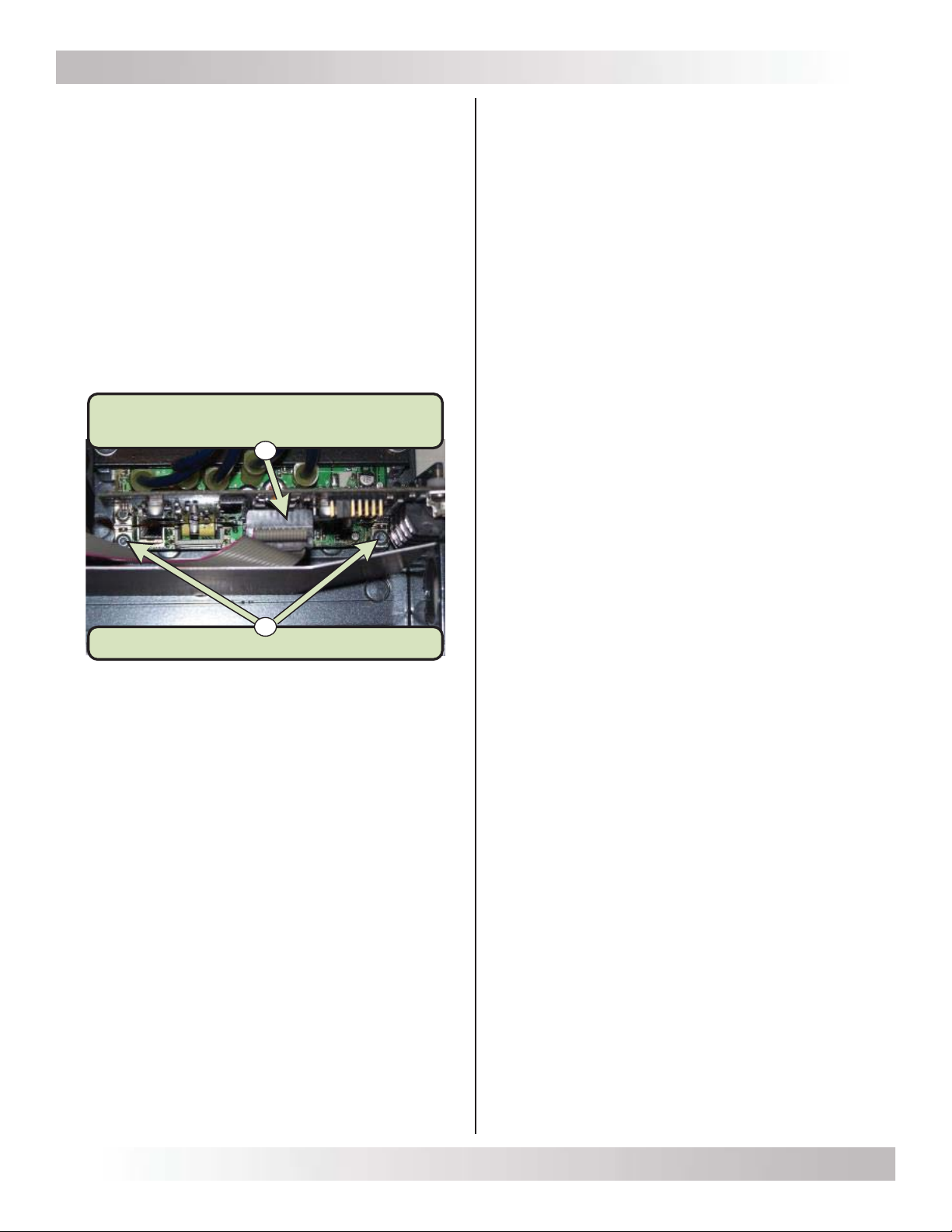
Figure 3, Top View of the Control Board
3. Grasp the control board by its top edge
(or upper corners) and firmly pull up to remove it from
the bottom 16-pin FET board connector.
4. Locate and pull off the 16-pin ribbon connector. See
Figure 3, Item A.
5. The control board is now removed. Using ESD
precautions, place it component-side up on a
grounded, static-free surface until it can be placed
in an antistatic bag to be returned with any other
replaced components.
3.2 Replacing ME/RD Series Control Boards
Note: If the FET board also needs to be replaced, follow the
information described in either the Small FET Board Removal
and Replacement, Service Instructions: 64-1004; or the Large
FET Board Removal and Replacement, Service Instructions:
64-1005; depending on your particular FET board—before
replacing the control board.
1. Remove the new control board from its antistatic
bag, and then reconnect the 16–pin ribbon cable
connector. Before pushing in the connector,
ensure it is seated with the red stripe on the
ribbon cable facing toward the rear of the inverter
(Figure 3, Item A) and the connector pins are aligned
correctly.
Two #6-32 screws (T15 head)
B
16-pin Ribbon Connector
(note red stripe toward rear of unit)
A
© 2018 Sensata Technologies 3
Control Board Removal and Replacement
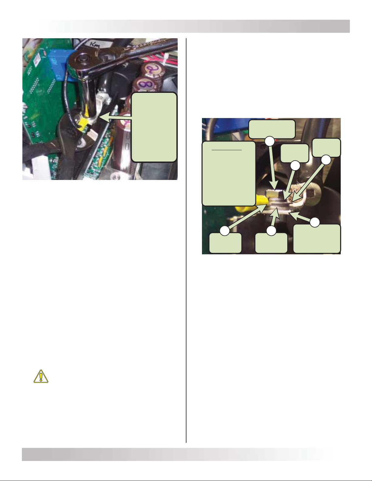
Figure 4, Preventing Busbar from Twisting
4.2 Replacing MS/MS-PAE Series Control Boards
Note: If the FET board also needs to be replaced, follow
the information described in the Large FET Board Removal
and Replacement, Service Instructions: 64-1005—before
replacing the MS/MS-PAE Series control board.
1. Remove the new control board from its antistatic bag
and place the loose side of the current sense wire
(Figure 7, Item B) back through the LEM.
2. Reconnect the 16–pin ribbon cable connector to the
front of the new control board. Before pushing it in,
ensure it is connected with the red stripe on the ribbon
cable facing toward the rear of the inverter (refer to
Figure 3, Item A for reference) and the connector pins
are aligned correctly.
3. Insert the new control board into the bottom 16-pin
FET board connector. Ensure the connector pins are
aligned correctly before pushing in.
4. Reconnect the negative bus cable and the current
sense wire (running through the LEM) to the negative
FET busbar using the ¼-20 bolt. This connection must
be torqued to 130 in.-lbs. Use a pair of pliers to hold
the negative FET busbar in place while this bolt is
being tightened to prevent the busbar from twisting
or breaking. See Figure 4 for reference.
Caution: Ensure the ¼-20 bolt is reconnected
in the same way as it was removed, and is
correctly torqued. This connection carries very
high DC current, and an improper connection
will affect the performance of the inverter and
may cause damage. See Figure 5 for reference.
Figure 5, Connections to Busbar
5. Secure the new control board into the bottom 16-pin
FET board connector by screwing in the two #6-32
screws (T15 head) to the FET board. See Figure 3,
Item B.
6. The new control board is now installed. Review all the
connections a final time to ensure they are correct.
7. If there are no other internal components to replace,
reinstall the top cover as described in the Top Cover
Removal and Replacement with Internal Component
Identification, Service Instructions: 64-1001.
Use pliers to
hold the
busbar
while
removing or
replacing
the
¼-20 bolt Sequence
1. ¼-20 bolt
2. Lock washer
3. Flat washer
4. Sense wire
5. Bus cable
6. Busbar
(captive nut)
¼-20 bolt
(7/16" head)
Busbar
(with captive
nut)
Bus
cable
Flat
washer
Lock
washer
Sense
wire
6
5
4
3
2
1
4© 2018 Sensata Technologies
Control Board Removal and Replacement
5.0 Identifying Components in the Control Board Compartment
Although Sensata offers multiple Magnum Energy inverter models—and uses a slightly different control board for each
model—the location of the control board for each inverter series is identical. Familiarize yourself with the components
involved in the removal and replacement of a control board.
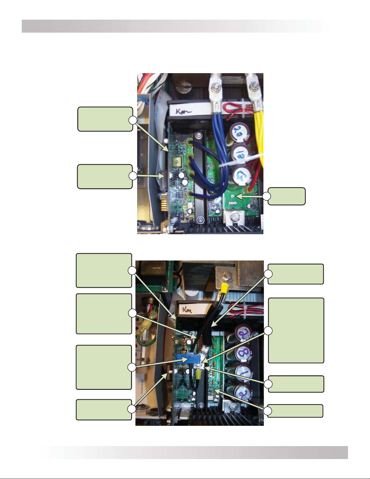
Figure 6, ME/RD Series Control Board Compartment
16-pin Ribbon
Cable Connector B
ME/RD Series
Control Board A
FET Board
C
Figure 7, MS/MS-PAE Series Control Board Compartment
Negative
Bus Cable
Negative FET
Busbar
FET Board
¼-20 bolt
(7/16" head) –
holds Negative
Bus Cable and
Current Sense
Wire to
Negative FET
Busbar
G
E
H
16-pin Ribbon
Cable Connector
LEM - current
transducer
(connected to
MS/MS-PAE
control board)
Current
Sense Wire
(1 or 2 wires,
depending on
model)
MS/MS-PAE
Series
Control Board
(LEM type)
A
B
C
D
F
This manual suits for next models
2
Other Sensata Remote Control manuals


