SensComp SonaSwitch MINI-A User manual
SonaSwitch®
General
This operation and installation manual provides
general guidelines and suggestions to assist you in
using the SensComp, Inc. ultra-sonic sensor module
in many measurement applications.
General Installation Procedures
1. Always mount the SonaSwitch® MINI-A in a
suitable dry location. The SonaSwitch® MINI-A
is designed to be used indoors or in protected
environments only. The SonaSwitch® MINI-AE
is suitable for harsher environments and higher
humidity conditions. Excessive moisture on the
circuit board (and the SonaSwitch® MINI-A
transducer) will result in damage and improper
operation, and will void all warranties.
2. Mount the SonaSwitch® MINI-A as far off the
ground as practical.
3. Mount the SonaSwitch® MINI-A in a location
where environmental interference sources are
minimized (examples are EMI sources, air
nozzles, excessive air turbulence, etc.).
4. Mount the SonaSwitch® MINI-A in a 1.575 inch
diameter hole, using RTV silicone or edge clips to
secure the sensor in place. You can also use our
Series 600 Housing unit, PID# 619395, to house
the SonaSwitch® MINI-A.
5. As supplied, the SonaSwitch® MINI-A has been
calibrated and will function without further
calibration.
System Wiring Information
Pin 1 – Power Supply – supplying 30 mA of current
(2.0 Amperes during the 0.5 ms transmit
pulse).
The 0 to 5 VDC analog output model
requires a +8 to +24 VDC regulated power
source.
The 0 to 10 VDC analog output model
requires a +12 to +24 VDC regulated
power source.
Pin 2 – Power Supply Common (Ground) – Common
Return for DC power supply, analog output,
and clock signals.
Pin 3 – External Trigger – Accepts TTL com-patible
logic level clock signals. A low to high (zero
to +5 VDC) transition triggers the SonaSwitch®
MINI-A
Pin 4 – Trigger Enable – Allows the SonaSwitch®
MINI-A to accept an external trigger signal.
Enabled by connecting this pin (pin 4) to common
(pin 2).
Pin 5 – Clock Output – Delivers a TTL compatible
Pulse Width Modulated (PWM) clock signal. This
signal goes high at the start of a cycle, and
returns to a low state when the returning echo is
received.
Pin 6 – Analog Output – 0 to +5 VDC (or 0 to +10
VDC) analog voltage output. Maximum analog
output current is 5 mA.
Pin 7 – Range Output – Normally high and goes low
when a target is detected between the MIN and
MAX range settings.
Calibration Procedures
Note: The SonaSwitch® MINI-A Sensor is calibrated
before it leaves the factory for the following settings:
SonaSwitch® MINI-A - 12 inch version:
[0 volts = 1 inch; max volts = 12 inches]
SonaSwitch® MINI-A - 20 foot version:
[0 volts = 6 inches; max volts = 20 feet]
SonaSwitch® MINI-A - 40 foot version:
[0 volts = 12 inches; max volts = 40 feet]
The following information provides calibration
techniques to obtain a more precise analog volt-age
output, setting the minimum and maximum target
points, and adjusting the receiver gain of the returning
echo signal.
1. Apply DC power (see requirements above) to the
SonaSwitch® MINI-A (connector header pin 1 &
pin 2).
2. Connect a DC Digital Volt Meter’s (DVM) Plus (+)
lead to the Analog Output (pin 6) and the
Minus (-) lead to Common (pin 2).
3. Allow five to ten minutes warm-up time for
the SonaSwitch® MINI-A to reach operating
temperature before calibrating the
unit.
4. Analog output voltage adjustment
(pin 6)
Point the sensor at an open space with no
items in the view of the sensor.
Verify the analog voltage output is 5.0
VDC (or 10.0 VDC).
Adjust the “SCALE ADJUST” potentio-
meter to the full-scale voltage desired
(+5.00 VDC or +10.00 VDC).
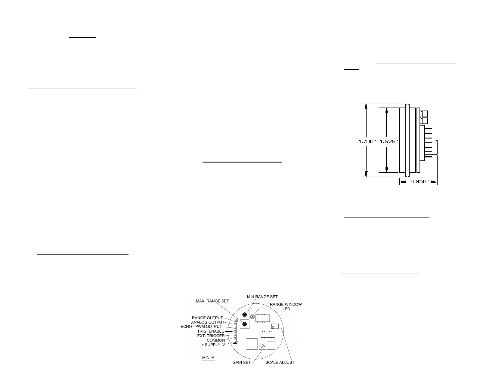
5. Setting Minimum/Maximum Ranges
Two push-button switches set the
SonaSwitch® MINI-A output voltage. These
independent range settings allow setting the
analog voltage output to change from zero
volts to full scale voltage output at desired
minimum and maximum distances between the
SonaSwitch® MINI-A sensor and the detected
object.
6. Maximum Voltage Range Setting
Place the target at the desired distance for
the full scale voltage output. This can be
either the minimum distance or the maximum
distance between the sensor and the target
(see step 5 above).
Depress and hold the “MAX RANGE SET”
push button, and wait for the “RANGE
WINDOW LED” indicator to stop flashing and
the transducer generates a “chirp” sound.

SonaSwitch
®
The SonaSwitch® MINI-A is now calibrated to
your desired target distance for full scale
analog voltage output.
7. Minimum Voltage Range Setting.
Place the target at the desired distance for the
minimum voltage output. This can be either
the minimum distance or the maximum
distance between the sensor and the target
(see step 5 above).
Depress and hold the “MIN RANGE SET”
push button, and wait for the “RANGE
WINDOW LED” indicator to stop flashing and
the transducer generates a “chirp” sound.
Note: The minimum voltage output will be a
value between 0.01 and 0.05 volts (50 mv),
due to the analog output’s amplifier offset
voltage.
The SonaSwitch® MINI-A is now calibrated to
your desired target distance for zero analog
voltage output.
8. Gain Adjustment
Note: The “GAIN” potentiometer has been preset
at the factory to provide the best performance for
the range of your SonaSwitch® MINI-A. In the
event that it is changed, the steps below will
assist you in returning it to the proper value
To calibrate the “GAIN” setting, place the
target at the maximum desired detection
distance.
Rotate “GAIN” pot fully counter clock-wise
(CCW).
Slowly rotate “GAIN” pot clockwise (CW) until
detection occurs.
Rotate “GAIN” pot clockwise (CW) an
additional 1/16 turn.
Note: Always calibrate “GAIN” for minimum
gain required for reliable detection. Excessive
gain may result in false target detection.
9. Range Window LED
The Range Window LED performs two
indication functions:
During Setup procedures, the LED will flash
as the set-up values are programmed into the
sensor.
During normal operation, the LED will illuminate,
indicating that a target is detected between the
“Minimum Range Set” point and the “Maximum
Range Set” point. For targets outside this range,
the LED will be off.
10. Range Output
The range output indicates when a target is
being detected between the MIN and MAX range
setting.
SonaSwitch® MINI-A &
SonaSwitch® MINI-AE
Push Button Settable
Ultrasonic
Sensor
Installation and
Operation
Manual

SensComp, Inc.
36704 Commerce Road
Livonia, MI 48150
Phone: 734-953-4783
Fax: 734-953-4518
www.senscomp.com
Copyright © 2004 SensComp, Inc. 15July2016
This manual suits for next models
1
Other SensComp Accessories manuals


Popular Accessories manuals by other brands

Bugaboo
Bugaboo parasol manual

Campingaz
Campingaz Powerbox 24L instruction manual

ROSE DISPLAYS
ROSE DISPLAYS ANOGRIP WITH CABLE CLIPS manual

ipf electronic
ipf electronic IV56E205-S quick start guide
354C03 Installation and operating manual")
PCB Piezotronics
PCB Piezotronics PCB-(M)354C03 Installation and operating manual

Rice Lake
Rice Lake 820i Operation manual


