Warning:
Do not use any SonaSwitch™ Ultrasonic Sensor in any application
to protect human life, health or safety or in any application where
failure of a SonaSwitch™ Ultrasonic Sensor may result in human
injury or death. This sensor must not be used in any environment
where risk of an explosion is possible.
General:
This operations and installation manual will provide general guide-
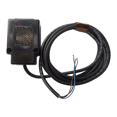
lines and suggestions in using the SonaSwitch™ 1650S Laser
series sonar detection module in many detection applications. If
further technical information is required, please contact us at in-
fo@edpcompany.com.
System Wiring:
1-RED Power supply: requires 10-30 VDC or 12-24
VAC with 1 ampere minimum current capac-
ity.
2-BLACK Return for AC power supply.
3-WHITE *Output relay 1: normally open (closes dur-
ing detection).
4-YELLOW *Output relay 1: relay common.
5-ORANGE *Output relay 1: normally closed (opens
during detection).
6-BLUE External Trigger [Clock input: requires TTL
compatible logic level clock signals (0-5
VDC)].
7-BROWN ECHO Output. (PWM) 0-5 volt TTL
8-GREEN GND (Return for DC power supply and
clock signals).
9-VIOLET *Output relay 2: normally open (closes dur-
ing detection).
10-GRAY *Output relay 2: relay common.
11-PINK *Output relay 1: normally closed (opens
during detection).
12-BRN/WHT Not Used.
13-BLK/WHT EXT. Trigger Enable (Active Lo).
14-RED/WHT REC Output (Actual returned echo’s from
target. TTL level).
15-Light GRN LASER ENABLE (Connect to supply
ground ).
*Relay contacts are dry, rated at 3.0 amperes, 28 VDC, non
-inductive loads. Exceeding these limits will cause perma-
nent damage and void warranty.
General Installation Procedures:
1. Always mount SonaSwitch™ 1650S in a suitable, dry
location. The SonaSwitch™ 1650S has been designed
for indoor or protected environments only. Excessive
moisture in the circuit board/transducer area will result in
damage and improper operation of unit and will void all
manufacturer’s warranties.
2. Mount SonaSwitch™ 1650S as far off the ground as
possible (minimum of 24 inches).
3. Adjust gain to minimum setting required to insure relia-
ble target detection. Excessive gain may result in false
detection.
4. Mount the unit in a location where environmental inter-
ference sources are minimized (example: EMI sources,
air nozzles, excessive air turbulence, etc.).
Calibration Procedure:
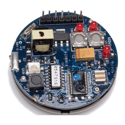
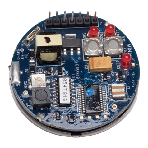
See figure 1.
1. Apply power to sensor.
2. Allow several minutes times to warm-up before calibra-
tion.
3. Set GAIN pot to 50%.
4. To set Range 1, place the target at the desired distance
in front of the sensor. Push and hold the Range 1 button
for 3 seconds, when you hear a “Chirp” release the but-
ton.
5. To set Range 2, place the target at the desired distance
in front of the sensor. Push and hold the Range 2 button
for 3 seconds, when you hear a “Chirp” release the but-
ton.
6. To calibrate the GAIN, place the target at the maximum
desired detection distance in front of the sensor. Now
decrease the GAIN adjust by rotating the potentiometer
CCW until the target is no longer detected. Next, in-
crease the GAIN by turning the GAIN adjust CW just
until the target is detected, give the potentiometer an
additional 1/16 of a turn CW.
NOTE: ALWAYS SET THE ‘GAIN FOR MINIMUM AMOUNT
NEEDED FOR DETECTION. EXCESSIVE ‘GAIN’ MAY RE-
SULT IN FALSE DETECTIONS.
7. Test the Range settings by slowly moving the target
towards and away from the sensor. Note that the corre-
sponding LED will be ON when the target is within the
set Range and the relays will active. Re-set Range set-
ting as required.
Note: Range settings are independent of air temperatures.
GAIN Adj.
(1-turn)
RANGE 1
RANGE 2
Figure 1
Laser
Enable
Laser Pointer:
Use the Laser point as an aide to aiming the sensor at the desired
target.
Note: Laser pointer is accurate to within +/- 3 Inches of the center point of the sensor.
To activate the Laser pointer push and hold the Laser Enable button
on the side of the sensor (fig.1) or by tying pin 15 of the DB-15 con-
nector on the sensor to ground.
