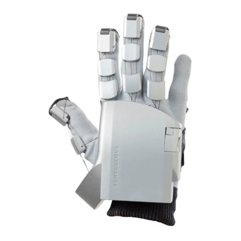
SenseGlove DK1 User manual

Getting started with the
SenseGlove DK1
November 2019 (v.1.3h)
Copyright SenseGlove © 2020 all rights reserved.

Table of Contents
What’s in the box
Mounting an HTC Vive tracker
Setup a SenseGloves pair
How to wear the SenseGlove
Setup a single SenseGlove
Getting started with your first project
How to contact us
Specifications
4
10
6
12
8
13
13
14
2

The SensGlove Developers Kit 1 (DK1) is a
prototype and not certified. SenseGlove or its
related companies cannot be held liable for
damages caused by the SenseGlove DK1. In using
the SenseGlove you accept all risks and liabilities.
The user is advised to follow the ‘getting started
guide’.
It is particularly important to use the USB
cables provided since they withstand the power
consumption of the SenseGlove.
We mention the HTC Vive tracker in this manual,
therefore, it should be noted that, HTC and Vive
are trademarks or registered trademarks of HTC
Corporation and its affiliates in the U.S. and other
countries.
Disclaimer
3

The schematics below gives the items you find
inside of the box. Underneath the LinkBox you can
find the required accessories.
SenseGloves
(left and right)
2x 3m (10ft)
USB cable
1x 2m (6.5ft)
USB cable
What’s in the box
1x
SenseGlove
LinkBox
1x Power
cable
4

2x HTC Vive
tracker
mount
2x Screw
(1/4-20UNC)
for mounting
the HTC Vive
tracker on the
adapter
2x Screw (M3
6mm, T10) for
mounting the
adapter on the
SenseGlove
5

The schematic below gives a correct SenseGlove
setup. What you need are:
• SenseGlove pair
• LinkBox
• Two long (3m / 10ft) USB cables
• One short (2m / 6.5ft) USB cable
• Power cable
Setup a SenseGloves pair
6

Step 1: Connect the LinkBox to the power. Install
the power cable in the LinkBox. Put the other side
of the power cable in a power socket (100-240V,
50-60Hz). If connected correctly, the Blue LED on
the LinkBox lights up.
Step 2: Connect the LinkBox with a computer.
Install the short USB cables with the micro USB
into the LinkBox. The other side of the short USB
cable should be connected to USB ports on a
computer.
Step 3: Connect the SenseGloves to the LinkBox,
with the two long USB cables. The micro USB
plug connects to the SenseGlove and the other
side of the cable is connected to the LinkBox.
Warning: Only use the provided
USB cables to connect the
SenseGlove. The provided USB
cables withstands the power
consumption of the SenseGlove,
regular USB cables might not.
7

The schematic on the next page shows how to
setup the SenseGlove. What you need are:
• SenseGlove
• LinkBox
• One long USB cable
• One short USB cable
• Power cable
If you use only one SenseGlove in your project, you
can follow the steps as indicated on the previous
page, using only one SenseGlove.
Setup a single SenseGlove
8

9

An HTC Vive tracker can be mounted on the
SenseGlove using the supplied mount. The
schematic on the next page shows the way to
install the HTC Vive tracker on the SenseGlove.
What you need are:
• SenseGlove
• Tracker mount
• Screw 1/4-20 UNC threaded mount
• Screw M3, 6 mm (T10)
• Screw driver Torx 10 (not provided)
Step 1: Attach the HTC Vive tracker to the mount
using the 1/4 inch UNC screw.
Step 2: Place the mount with attached tracker
on the SenseGlove corresponding to the middle
finger, and attach it with the M3 screw.
Mounting an HTC Vive tracker to the
SenseGlove
10

11

The SenseGlove is best installed on a hand as
described below. In addition, the schematic on
the next page shows how it is done.
Step 1: Place the SenseGlove on your hand.
Orient the SenseGlove so that the palm is facing
upwards. You can rest the SenseGlove on a table
or in your other hand. Place your hand, with the
palm side up, under the Velcro straps so that the
thumb is positioned between both straps.
Step 2: Tighten the two Velcro straps to fix the
SenseGlove on the palm of the hand. Do not fix it
too tight.
Note: It is best to leave the Velcro attached on the
attachments used for both straps. Adjusting the
Velcro is best done on the side with separate Velcro
attachments.
Step 3: Attach the SenseGlove to your fingertips,
by placing your fingers inside the finger straps.
Make sure the straps are attached to the fingertips
(the distal phalanx). Tighten the straps.
How to wear the SenseGlove
12

Now that you have setup the SenseGlove you are
ready to use it! The only thing you need is the
Software Development Kit (SDK) for Unity. The
SDK includes a few example projects you can use
to try your SenseGlove. You can download the
SDK and its documentation here:
https://github.com/Adjuvo/SenseGlove-Unity
If you experience problems or if you have
questions, please contact us. For questions or
concerns, contact:
• +31 6 4098 8831
• helpme@senseglove.com
Getting started with your first project
How to contact us
13

Specifications
Features Specs
Motion Capturing - 9-axis absolute orientation
sensor in the wrist.
- 20 rotation sensors in
the exoskeleton linkages
corresponding with each
joint in the hand.
Force Feedback - 5 proprietary passive
force feedback modules
delivering a maximum force
of 40N in extension direction
at the fingertips
- A force resolution with
an average of 0.4N per
programmable step.
Haptic Feedback - 5 haptic motors of max 0.8G
located in each fingertip.
- 1 haptic actuator for impact
simulation of 7.3G located
in the palm hub of the
SenseGlove.
14

Power Consumption - A maximum peak current
draw of 2.8A per SenseGlove.
- In average use a 1.5A per
Sense Glove.
- Without any feedback the
current draw is 0.18A per
SenseGlove.
Communication - USB serial communication:
A limited 100hz refresh rate
guaranteed.
General - Weight: ~300g (10.6 oz) per
glove.
- Size: L 250mm x W 140mm
x H 50mm.
Positional Tracking - Motion capturing delivers
accurate finger tracking.
For tracking of the forearm
in the Cartesian space an
external system is required,
e.g., the HTC Vive Steam
VR tracker (not part of a
SenseGlove set).
15
Table of contents
Other SenseGlove Robotics manuals
