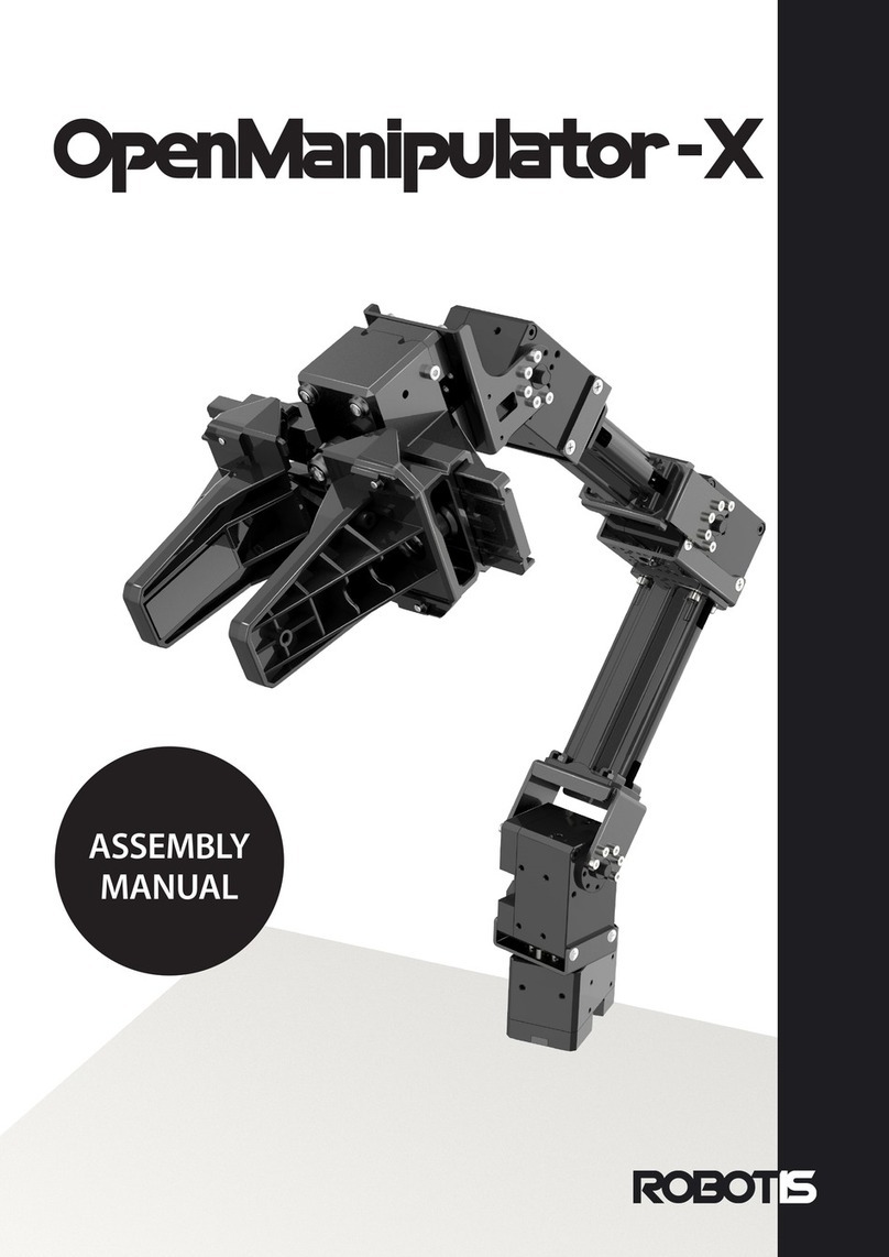
Robotis HAND RH-P12-RN-UR User manual

User Manual

RH-P12-RN-UR User Manual v1.1.0
-2-
Contents
1. Introduction .......................................................................................................................3
1.1. Package Contents.................................................................................................................3
1.2. H/W Specification.................................................................................................................3
2. Mechanical Interface........................................................................................................ 4
2.1. Mounting ....................................................................................................................................4
2.2. Dimensions.................................................................................................................................6
2.3. Work Space .............................................................................................................................6
3. Electrical Interface .......................................................................................................... 7
3.1. External Port...........................................................................................................................7
3.2. Communication Connector................................................................................................. 7
3.3. Robot Cable.............................................................................................................................8
4. Software Setup ................................................................................................................9
4.1. Installing URCap Package .................................................................................................9
4.2. Setup Tool I/O Interface Control.............................................................................. 11
4.3. Start DYNAMIXEL Controller Daemon .................................................................... 12
4.4. Gripper Test from Toolbar ........................................................................................... 13
5. Programming ....................................................................................................................14
5.1. Gripper Torque Node....................................................................................................... 14
5.2. Grip Detection Node......................................................................................................... 15
5.3. Gripper Move Node........................................................................................................... 17
RH-P12-RN-UR User Manual v1.1.0
-3-
1.Introduction
The RH-P12-RN-UR is 1-DoF 2-Finger Adaptive Gripper that can be compatible with
e-Series of UNIVERSAL ROBOTS.
Adaptive gripping design is applied to pick objects in different sizes and shapes. It
features light weight and high power with current control (torque control).
1.1. Package Contents
①Gripper (RH-P12-RN) x1
②Bracket (FRP42-A120K) x1
③L-Wrench x2
④Cable Cover x1
⑤USB Stick x1
⑥WB M6x08 x4
⑦WB M3x08 x4
⑧WB M3x04 x2
⑨Robot Cable-X4P for UR 180mm x1
1.2. H/W Specification
Properties
Data
Weight
500 g
Recommended Payload
5 kg
Maximum Stroke
106 mm
Diameter for Encompassing Grip
50 ~ 100 mm
Maximum Gripping Force
170 N
Nominal Voltage
24 V
Standby Current
30 mA
Peak Current
3.33 A
Operating Temperature
-5 ~ 55 ℃
Network Interface
RS485

RH-P12-RN-UR User Manual v1.1.0
-4-
2.Mechanical Interface
The RH-P12-RN maintains torque only when power is being supplied.
2.1. Mounting
RH-P12-RN-UR is compatible with e-Series of UNIVERSAL ROBOTS.
①Align the bracket with the guide pin and mount it on your robot arm.
②Fix the bracket using the provided M6x08 screws.
③Align the direction of the cable connector and mount the gripper (RH-P12-RN) on
the bracket.

RH-P12-RN-UR User Manual v1.1.0
-5-
④Fix the gripper using the provided M3x08 screws.
⑤Make sure the power is off before connecting them using a robot cable.
Otherwise, it may cause unexpected problems.
⑥Plug the provided cable to either of cable connectors on the gripper (RH-P12-RN)
and robot arm’s wrist connector.
⑦Fix the cable cover using the provided M3x04 screws to cover the cable
connector of the gripper.

RH-P12-RN-UR User Manual v1.1.0
-6-
2.2. Dimensions
2.3. Work Space
Following image shows the range of RH-P12-RN work space between 2 fingers.

RH-P12-RN-UR User Manual v1.1.0
-7-
3.Electrical Interface
3.1. External Port
Remove bolts and cover plate to reveal the external port.
Pin 1
Pin 2
Pin 3
Pin 4
Pin 5
Pin 6
GND
3.3V
PORT1
PORT2
PORT3
PORT4
An external port of RH-P12-RN contains 6-pins for Digital I/O and Analog Input. But
the feature is not available for PolyScope.
3.2. Communication Connector
Pin 1
Pin 2
Pin 3
Pin 4
GND
VDD
DATA+
DATA-

RH-P12-RN-UR User Manual v1.1.0
-8-
3.3. Robot Cable
The provided robot cable is made of dual pin power supply to increase output
current.
Pin
Color
Signal Type
Description
1
White
AI2/RS485+
Analog in 2 or RS485+
2
Brown
AI3/RS485-
Analog in 3 or RS485-
3
Green
TI1
Digital Input 1
4
Yellow
TI0
Digital Input 0
5
Gray
PWR
Power (0V/12V/24V)
6
Pink
TO1/GND
Digital Outputs 1 or Ground
7
Blue
TO0/PWR
Digital Outputs 0 or 0V/12V/24V
8
Red
GND
Ground

RH-P12-RN-UR User Manual v1.1.0
-9-
4.Software Setup
PolyScope version should be 5.5 or higher (for e-Series) in order to install the
URCap Package from ROBOTIS.
4.1. Installing URCap Package
The USB stick in the package contains the .urcap file provided by ROBOTIS.
Please visit ROBOTIS download center(http://www.robotis.com/) to find the latest URCap.
①Insert the USB stick that contains .urcap file into the USB connector of teach
pendant.
②Tap the triple bar icon in the upper right corner and select the “Settings”menu.
③Tap the “System”menu on the left. Tap the “URCaps”submenu and then tap the
“+”button at the bottom of the screen.

RH-P12-RN-UR User Manual v1.1.0
-10 -
④Open the “ROBOTIS_RH_P12_RN-X.X.X.urcap”file from usbdisk, and tap the
“Restart”button to activate the URCap.

RH-P12-RN-UR User Manual v1.1.0
-11 -
4.2. Setup Tool I/O Interface Control
Follow the instructions below to supply power and connect RS485 communication to
the gripper (RH-P12-RN) using Tool I/O Interface.
①Go to the “Installation”tab.
②Tap the “General”menu on the left and then tap the “Tool I/O”submenu.
③On “I/O Interface Control”, select “ROBOTIS Gripper (RH-P12-RN)”from the
“Controlled by”dropdown lists.
④The “Tool Analog Inputs”and “Digital Output Mode”sections will be automatically
configured and locked.

RH-P12-RN-UR User Manual v1.1.0
-12 -
4.3. Start DYNAMIXEL Controller Daemon
DYNAMIXEL Controller Daemon should be running in order to communicate with the
gripper in RH-P12-RN URcap.
①Go to the “Installation”tab.
②Tap the “URCaps”menu on the left and then tap the “Gripper”submenu.
③Verify that the daemon is running.
④Please uncheck “Use the Tool Communication Interface on the wrist.”Option if
the gripper is powered and controlled directly by the control box via a separate
USB to RS485 interface device due to an insufficient power at the Tool
Communication Interface.
⑤If I/O Interface Control has not been configured in “4.2. Setup Tool I/O Interface
Control”,the following warning message will appear.
⑥The following warning message will appear if PolyScope version is lower than 5.5.

RH-P12-RN-UR User Manual v1.1.0
-13 -
4.4. Gripper Test from Toolbar
UR+ Toolbar contains functions to test the gripper.
The toolbar is included in the URCap package, and installing the URCap package will
automatically install the toolbar as well.
Tap the “UR+”icon at the top right menu to display the toolbar.
-Torque Control : Select “Enable”or “Disable”to activate the torque of gripper.
When the torque is disabled, gripper will neither open nor close.
-OPEN/CLOSE : Select “OPEN”or “CLOSE”button to test the gripper operation.
The torque will be limited for safety reasons.
-Gripper Position : Displays present gripper stroke.
-Grip Detection : Displays if the grabbing an object is “Detected”or “Not
detected”.
-The following warning message will appear if communication with the gripper fails
due to the power down or the configuration error.

RH-P12-RN-UR User Manual v1.1.0
-14 -
5.Programming
Please add the gripper control node in order to control the gripper using a robot
program.
①Go to the “Program”tab.
②Tap the “URCaps”button in the navigation panel on the left.
③Select the node to add on the robot program.
④Select “Command”tab from the node section on the right and edit the command.
⑤If I/O Interface Control has not been configured in “4.2. Setup Tool I/O Interface
Control”,the following warning message will appear under “Gripper Torque”,
“Grip Detection”, and “Gripper Move”nodes.
5.1. Gripper Torque Node
The “Gripper Torque”node is used to enable or disable the torque of gripper
connected to the robot arm.
Selecting “Torque Enable”option will turn on the torque of gripper when this node is
executed in the robot program.
Selecting “Torque Disable”option will turn off the torque of gripper when this node
is executed in the robot program. Executing “Gripper Move”node will not take
effect while torque is disabled.
The gripper (RH-P12-RN) may not hold the present position (stroke) and will be
backdrivable when torque is disabled.

RH-P12-RN-UR User Manual v1.1.0
-15 -
5.2. Grip Detection Node
The “Grip Detection”node is used to detect whether the gripper has grabbed an
object and provide conditional statement thereof.
The “Grip Detection”node is pre-packaged as an If statement that prompts the user
to select between if the object is detected and if the object is not detected.
In case of “If”conditional statement under the “Grip Detection”node turns out to be
true, the following command will be executed. The “Else”node can also be appended
in the program tree by pressing “Add Else”button in the command tab.

RH-P12-RN-UR User Manual v1.1.0
-16 -
In case of the conditional statement of “If”node is false, the command followed by
“Else”node will be executed. Press the “Remove Else”button in the command tab to
remove the “Else”node and execution commands followed by.

RH-P12-RN-UR User Manual v1.1.0
-17 -
5.3. Gripper Move Node
The “Gripper Move”node is used to control the gripper using Position, Velocity Limit
and Force Limit parameters.
The “Position”that stands for the desired gripper stroke can be entered in the
range of 1 ~ 106 mm.
The “Velocity Limit”controls the maximum velocity limit of gripper motion with the
range of 1 ~ 100 %.
The “Force Limit”controls the maximum limit of the grabbing or releasing force with
the range of 0 ~ 100 %.
Press the “GO TO POSITION”button to apply above parameters to the gripper(RH-
P12-RN). Please be aware that this will automatically enable the torque even if the
torque has never been enabled.
However, in case of communication failure due to power down or configuration error,
“GO TO POSITION”button will be disabled.

RH-P12-RN-UR User Manual v1.1.0
-18 -
http://www.robotis.com
KOREA korea@robotis.com
CHINA china@robotis.com
USA america@robotis.com
Others contac[email protected]
JAPAN [email protected]om
This manual suits for next models
1
Table of contents
Other Robotis Robotics manuals

Robotis
Robotis BIOLOID GP User manual

Robotis
Robotis BIOLOID GP User manual

Robotis
Robotis Beginner level robot series User manual

Robotis
Robotis OpenManipulator-X User manual

Robotis
Robotis STEM LEVEL1 User manual

Robotis
Robotis Dynamixel RX-64 User manual

Robotis
Robotis Comprehensive Kit Robot Series User manual

Robotis
Robotis dynamixel AX-12 User manual