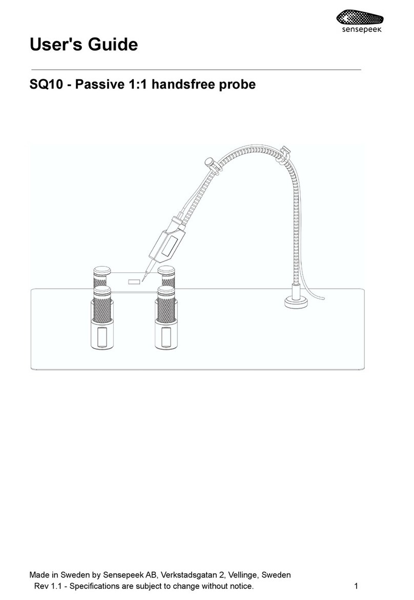
Sensepeek SP10 User manual

User's Guide
SP10 - Passive 1:1 hands-free probe
Made in Sweden by Sensepeek AB, Verkstadsgatan 2, Vellinge, Sweden
Rev 1.0 - Specifications are subject to change without notice. 1

Introduction
This passive 1:1 probe is suitable for signal measurements and logic
analyzers for high speed serial communication interfaces like SPI, CAN,
USB, JTAG, I2C, UART etc. The probe can also be used for resistance
and voltage measurements, power and grounding of devices with
continues currents of maximum two ampere.
Warranty
Sensepeek products are warranted for 12 months from the date of
purchase. The warranty covers defects in material and workmanship.
This warranty does not apply to components (parts and accessories)
subject to natural and normal wear and tear. This warranty does not in
any way limit the rights you have under mandatory law.
Disposal
Sensepeek offers our customers the opportunity to return
products at the end of their functional lives to Sensepeek for
recycling. Qualifying products are marked with the WEEE
symbol shown above. Or ensure WEEE compliant collection
and treatment yourself. Do not dispose of this product as
unsorted municipal waste
Delivery cost of any authorized product returned to Sensepeek will be at
the expense of the sender.
Safety
To prevent possible death, personal injury, electrical shock, fire or
damage to the product, carefully read this safety information before use
of the product. Follow all generally accepted safety practices and
procedures for working with and near electricity. The product has been
designed in accordance with the IEC 61010‑031 standard and left the
factory tested and in a safe condition.
Safety descriptions found throughout this user guide:
A WARNING identifies conditions or practices that could
result in death or injury. To prevent injury or death only
2

qualified personnel should use this product, only as
instructed and with only accessories supplied or
recommended. Protection provided by the product may be
impaired if used in a manner not specified in this guide.
A CAUTION identifies conditions or practices that could
result in damage to connected product or equipment.
Maximum input ranges
The full-scale measurement ranges are the maximum voltages that can
be accurately measured by the probe for safe operation. The
overvoltage ranges are the maximum voltages that will not damage the
probe.
WARNING To prevent electric shock, do not connect the
probe to voltages exceeding the levels specified in this user
guide and do take all necessary safety precautions when
working on equipment where hazardous live voltages may
be present.
WARNING Do not connect to a mains voltage or a derived
voltage that can carry the overvoltage transients that may
be present. Note that the probe's maximum input voltage
rating decreases as the frequency of the applied signal
increases. This probe does not carry a measurement
category rating.
Grounding
WARNING Do not ever connect the ground input to, or allow
it to touch, any electrical potential other than ground. To
prevent death or personal injury, always measure that there
is no significant DC or AC voltage between the probe
ground and the point to which you intend to connect it.
3

CAUTION Applying a voltage to the ground input is likely to
cause permanent damage to the probe or other connected
equipment.
Environment
WARNING To prevent death or injury, do not use near
explosive vapor or gas.
CAUTION To prevent damage to the probe, always operate
and store your probe according to the levels specified in this
guide.
Care of the product
The probe contains no user-serviceable parts.
WARNING To prevent death or injury, do not try to open any
part of the assembly, do not use the product if it appears to
be damaged in any way, and stop use immediately if it
behaves abnormally.
CAUTION Always handle with care to avoid injury from the
sharp tip. Ensure that the probe is completely dry before
use. Do not allow liquids to enter the probe. Take care to
avoid mechanical stress or tight bends on the arm and
cable connecting the probe head to the oscilloscope.
Mishandling will degrade performance and measurement
accuracy and is not covered by the warranty. Avoid all kind
of mechanical shock to the probe assembly.
4

Overview
1. Probe head
2. Pin head connector (signal)
3. Probe arm
a. Probe base (with magnet)
b. Flexible arm
c. Probe arm grip
Getting started
1. Attach probe head to the probe arm with the M4 thread
2. Connect your instrument to the pin head connector
Operating Instructions
Position the probe - Place the probe foot on the base plate and the
magnet will keep it in place.
5

Reposition the probe - Slide the probe foot on the base plate.
Detaching the probe - Tilt the probe foot gently and remove the probe
arm. Avoid pulling in the flexible arm!
Measuring with the probe
1. Lift the probe in the probe grip
2. Compress the needle to the measuring target
3. Release the probe grip gently
Probe needle replacement
1. Notice the replaceable needle tip. Please be aware of the sharp
needle tip!
2. Pull out the replaceable needle tip by hand or use pliers.
3. Pick up the new needle tip and insert in the sleeve with pliers.
6

7

Specifications
Probe Characteristics
Model
SP10
Bandwidth > (MHz)*
10
Rise time (ns), calculated
34
Attenuation Ratio
1
Needle Resistance (ohm) <
0.02
Full-scale measurement
range (for safe operation) Maximum Input: 1:1
Input Voltage, Fulfill the signal voltage limits of
EN 61010-031:2015
Voltage: +/-60 V DC, 30 V AC RMS, +/-42.4 V pk
max.
Overvoltage protection
(voltage that will not damage)
200 V DC + peak AC
Maximum DC current (A)
2
Operating Environment, Max. altitude 2km
-40 to +80 °C, 0 to 80% RH
Storage Environment, Max. altitude 15km
-40 to +80 °C, 0 to 80% RH
Probe tip diameter (mm)
0.5
Probe tip angle (Degrees)
30
RoHS and REACH compliant
Yes
*The probe and cable are not impedance matched and are suitable for measurements below
10MHz, frequencies above 10 MHz can still be measured but with increased signal distortion
on rising and falling edges using oscilloscope. The probe and cable are tested above 25
MHz with correct data decoding with common logic analyzer.
8
Table of contents
Other Sensepeek Measuring Instrument manuals
Popular Measuring Instrument manuals by other brands
EUTECH INSTRUMENTS
EUTECH INSTRUMENTS pH 600 instruction manual

Schwaiger
Schwaiger STEM1180 user guide
Worldcast Systems
Worldcast Systems Audemat FM Monitor user manual

YOKOGAWA
YOKOGAWA AQ6373B Getting started guide
Seametrics
Seametrics jWAVE instructions

Bacharach
Bacharach HGM300 Installation & operation
PCE Americas
PCE Americas PCE-WM 1 manual
Wohler
Wohler Smart Connect SC 660 operating instructions
Dwyer Instruments
Dwyer Instruments RVM Specifications-installation and operating instructions
Monacor
Monacor 0171950 instruction manual
Extech Instruments
Extech Instruments MO750 user guide
Team
Team SWR 1180 W operating instructions
