Sensia CLIF MOCK TC2000 User manual

Manual No. 9A-70165002, Rev. 02
MEASUREMENT
CLIF MOCK™
True Cut 2000 Sampler
Controller
Installation, Operation & Maintenance Manual
MODEL: TC2000

True Cut 2000 Sampler Controller
2
Page Left Intentionally Blank

3
Important Safety Information
Terms Used in This Manual
Caution
Caution, risk of electric shock
Attention
Attention, risque d'électrocution
WARNING
A warning identifies information about practices or circumstances
that can lead to personal injury or death, property damage, or
economic loss.
AVERTISSEMENT
Un avertissement identifie des informations sur des pratiques ou
des circonstances pouvant entraîner des blessures corporelles ou
la mort, des dommages matériels ou des pertes économiques.
Caution
Caution statements Indicate actions or procedures which, if not
performed correctly, may lead to personal injury or incorrect function of
the instrument or connected equipment.
Attention
Indiquez les actions ou les procédures qui, si elles ne sont pas
effectuées correctement, peuvent entraîner des blessures ou un
mauvais fonctionnement de l'instrument ou de l'équipement connecté.
Note
Indicates additional information about specific conditions or
circumstances that may affect instrument operation.
Remarque
Indique des informations supplémentaires sur des conditions ou des
circonstances spécifiques pouvant affecter le fonctionnement de
l'instrument.
REVISION HISTORY
REVISION:
DESCRIPTION OF CHANGE:
ISSUER:
APPROVER:
DATE:
1
Initial Release
AK
TMM
June 2011
2
Update Electronics Package
AK
TMM
September
2020

True Cut 2000 Sampler Controller
4
Table of Contents
Section 1: Introduction.................................................................................................................7
Description......................................................................................................................................................... 7
Section 2: True Cut 2000 Sampler Controller Components and Specifications.......................8
Display............................................................................................................................................................... 8
Power Supply..................................................................................................................................................... 8
Product Identification......................................................................................................................................... 8
Specification ...................................................................................................................................................... 9
Section 3: Installation.................................................................................................................11
General Information......................................................................................................................................... 11
Mounting Options............................................................................................................................................. 11
Hazardous Area Installations........................................................................................................................... 11
Class I, Division 1 (CSA) Installations....................................................................................................... 11
Class I, Division 2 (CSA) Installations....................................................................................................... 12
Field Wiring...................................................................................................................................................... 12
Grounding Procedures .............................................................................................................................. 13
External DC Power Supply........................................................................................................................ 14
Communications........................................................................................................................................ 15
Turbine Input ............................................................................................................................................. 15
Digital Output (Solid State Relay).............................................................................................................. 16
Section 4: Operating the Controller...........................................................................................17
Front Panel ...................................................................................................................................................... 17
Keypad Overview............................................................................................................................................. 17
Common Keypad Functions ............................................................................................................................ 18
Stop a Sampling Period............................................................................................................................. 18
Start a Sampling Period............................................................................................................................. 18
Pause and Resume Sampling Without Starting a New Sampling Period ................................................. 18
Display Status Indicators On Demand ...................................................................................................... 18
Test the Controller..................................................................................................................................... 18
On-Demand Display of Status Indicators and Volumes .................................................................................. 18
Run Time................................................................................................................................................... 19
Percent Done............................................................................................................................................. 19
Flow Rate................................................................................................................................................... 19
Total Volume ............................................................................................................................................. 19
Grand Total Volume .................................................................................................................................. 19
System Voltage ......................................................................................................................................... 19
Sampler Status.......................................................................................................................................... 19
Firmware Version ...................................................................................................................................... 20
Samples Taken.......................................................................................................................................... 20
Section 5: Programming the Controller.....................................................................................21
Time-Based Sampling ..................................................................................................................................... 21

5
Batch/ Time Sampling ............................................................................................................................... 21
Continuous Time Sampling ............................................................................................................................. 22
Volume-Based Sampling................................................................................................................................. 22
Volume Sampling ...................................................................................................................................... 22
Sampler Test ................................................................................................................................................... 23
Keypad Security............................................................................................................................................... 23
Disable Security......................................................................................................................................... 23
Basic Security............................................................................................................................................ 23
Advanced Security..................................................................................................................................... 24
Access Menu ................................................................................................................................................... 24
Communication Port Settings.................................................................................................................... 24
Reset All Totals ......................................................................................................................................... 24
Load Factory Default Settings ......................................................................................................................... 24
Security Bypass............................................................................................................................................... 24
Section 6: True Cut 2000 Sampler Controller Spare Parts.......................................................26
Appendix A: Communications Protocol....................................................................................30
Introduction...................................................................................................................................................... 30
Supported Commands..................................................................................................................................... 30
Data Types ...................................................................................................................................................... 30
Registers.......................................................................................................................................................... 30
Appendix B: Publisher Notes.....................................................................................................34
Support ............................................................................................................................................................ 34
Warranty .......................................................................................................................................................... 34
Disclaimer........................................................................................................................................................ 34
Contact us........................................................................................................................................................ 36

6
GENERAL
WARNING!
To avoid the risk of electric shock and fire, the following safety instructions must be
observed and the guidelines followed.
The specifications must not be exceeded, and the device must only be applied as
described in the following.
Prior to the installation and commissioning of the unit, the installation guide must be
examined carefully.
If the equipment is used in a manner not specified by the manufacturer, the protection
provided by the equipment may be impaired.
GENERAL
AVERTISSEMENT!
Pour éviter tout risque de choc électrique et d'incendie, les consignes de sécurité de ce
manuel doivent être observées, et les instructions suivies.
Les spécifications ne doivent pas être dépassées, et l'unité ne doit être appliquée que
comme décrit dans le texte suivant.
Ce manuel doit être examiné avec soin, avant l'installation et la mise en service de
l'unité.
Si l'équipement est utilisé d'une manière non spécifiée par le fabricant, la protection
assurée par l'équipement peut être altérée.
INSTALLATION
WARNING!
Installation may only be carried out by electrically skilled and instructed personnel in
accordance with national legislation, including the relevant standards.
All technical data on the instrument is to be observed.
Changes to the design and modifications to the equipment are not permitted.
The equipment shall only be operated as intended and only in undamaged and perfect
condition.
Sufficient segregation must exist between different cables and wires carrying different
types of signal or power and all other circuits.
All wires must be terminated, complete with crimping lugs. Unused cores should be
terminated to the earth bus bar.
INSTALLATION
AVERTISSEMENT!
L’installation ne peut être effectuée que par un électricien qualifié, conformément à la
législation nationale, y compris les normes pertinentes.
Toutes les données techniques sur l'instrument doivent être observées.
Modifications de l'équipement ne sont pas autorisés.
L'équipement ne doit être utilisé comme prévu par le fabriquant et uniquement si il est
en parfait état.
Une séparation suffisante doit exister entre les différents câbles et les fils transportant
différents types de signaux ou de puissance et tous les autres circuits.
Tous les fils doivent être terminés, avec pattes de sertissage. Les noyaux non-utilisés
doivent être terminés au jeu de barres de la terre.

Section 1: Introduction
7
Section 1: Introduction
DESCRIPTION
The Clif Mock True Cut 2000 Sampler Controller, see Figure 1, is an electronic controller that can be used to
control any pneumatic device. When paired with a liquid/gas sample pump, the device is ideal for sampling
liquid or gas flow streams.
The controller can be configured to sample as time proportional or flow proportional. This design allows
external pacing devices such as turbines meters to control the sampling frequency.
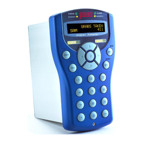
The controller consists of an explosion proof enclosure with a window for viewing a dual LCD and a six-key
keypad, press control switch and electronic circuitry, see Figure 1.
Figure 1: True Cut 2000 Sampler Controller

True Cut 2000 Sampler Controller
8
Section 2: True Cut 2000 Sampler Controller
Components and Specifications
DISPLAY
Dual readouts in the front panel display provide a real-time sample count during operation and guide users
through configurable settings during device setup. In addition, a user can initiate a scrolling display of
performance status indicators and total volumes on demand during normal operation. Run time, percentage
of sample job completion, flow rate, total volume, grand volume, system voltage, sampler status, firmware
version, and sample count are recorded by the controller and available for display. See Section 4, for details.
Figure 2: True Cut 2000 Sampler Controller, internal view
POWER SUPPLY
The True Cut 2000 Sampler Controller supports external DC power input supply. An external 6 to 30V DC
power supply with a minimum of 65mA can be used to power the controller circuit board.
PRODUCT IDENTIFICATION
A serial tag mounted on top of the enclosure identifies the product by its part number and serial number, see
Figure 3. The current model of serial tag reflects Scanner 2000 microEFM, under Model it will show either
TC2000 (Electronics Controller) or LGS-2000 (Sampling System).

Section 2: True Cut 2000 Sampler Controller Components and Specifications
9
Figure 3: Serial Tag
SPECIFICATION
Table 1: TC2000 Sampler Controller
Enclosure
Explosion Proof, Type 4 enclosure
Keypad
6-Key membrane switch, Password-protected security available
Switch
Explosion Proof external Momentary Control Switch
Power Supply
6-30V DC external power supply
Operating Environment
True Cut 2000 Sampler Controller: -40°C to 70°C (-40°F to 158°F)
0 to 90% non-condensing relative humidity
LCD contrast is reduced below -30°C (-22°F)
Turbine Meter Input
Configurable sensitivity adjustment (20 mV to 200 mV, peak to peak)
Frequency range: 0 to 5000 Hz
Continuous 50/50 duty cycle
Programmable K-factor
Input amplitude: 20 mV to 3000 mV,peak to peak
Turbine
Setting
Input Sensitivity
0 –1000 Hz
1000 –2000
Hz
2000 –3500
Hz
3500 - 5000
Hz
Low (20 mV)
20 mVpp
25 mVpp
50 mVpp
50 mVpp
Med (50 mV)
50 mVpp
70 mVpp
110 mVpp
140 mVpp
High (100
mV)
100 mVpp
150 mVpp
250 mVpp
350 mVpp
Highest (200
mV)
200 mVpp
380 mVpp
620 mVpp
850 mVpp
LCD Display
8-digit top readout of values (7-segment characters)
6-digit bottom readout of scrolling parameters and associated
engineering units (11-segment characters for easy-to-read prompts)
0.3” character height
Configurable scan parameters and duration
8-digit top readout of values (7-segment characters)
Digital Output, Solid State Relay
Rated 30V DC, 60mA max.

True Cut 2000 Sampler Controller
10
Sampling Methods (Time)
Batch Sampling (controller calculates the frequency of samples
required to fill the bottle in a specified time)
Time Sampling (controller collects samples at user-configured
frequency until specified number of samples is collected)
Continuous Time Sampling (controller collects samples at user-
configured frequency until sampling period is manually terminated)
Sampling Methods (Volume)
Turbine Input (controller collects samples to deliver specified volume,
based on turbine input frequency settings)
Volume Units
GAL, BBL, M3, LIT, CF, and NONE
Rate Units
/SEC, /MIN, /HR, and /DAY
Security
Two security levels with password protection
Communications
2 RS-485 communication ports (RTU Modbus®)
Safety Approval
True Cut 2000 Sampler Controller
Approved by CSA for US and Canada
Class I, Division 1, Groups B, C and D (explosion-proof)
Class I, Division 2, Groups A, B, C and D (non-sparking)
Type 4 enclosure
T6 temperature class

Section 3: Installation
11
Section 3: Installation
GENERAL INFORMATION
The True Cut 2000 Sampler Controller is typically installed after the sample probe and flowmeter are
installed in a pipeline.
For sampling liquid or gas, the controller should be installed with a sample pump, a sample probe, a
pressure regulator, a flowmeter, and a receiver. In liquid applications, hazardous gas applications, and low-
pressure gas applications, an external air supply is also required.
Note
This manual describes the installation of the True Cut 2000 Sampler
Controller. For LGS-2000 Sampling System, refer to the LGS-2000
Sampling System User Manual, Part Number 9A-70165003 for
additional details.
MOUNTING OPTIONS
The controller is mounted on the backplate of LGS-2000 system where the system can be direct mounted or
remote mounted. Refer to LGS-2000 Sampling System User Manual for details. True Cut 2000 Sampler
Controller can be mounted remotely using the optional remote mount kit, see Figure 2.1 below.
Figure 4: Remote Mount Option
HAZARDOUS AREA INSTALLATIONS
CLASS I, DIVISION 1 (CSA) INSTALLATIONS
True Cut 2000 is CSA-certified as explosion-proof for Class I, Division 1, Groups B, C and D hazardous
location when sold individually.
Wiring Precautions

True Cut 2000 Sampler Controller
12
Caution
All signal cable from other devices and power must be installed
accordance with local wiring practices for area classification. The cable
used between the True Cut 2000 and other devices must be either
armored MC-HL type cable or standard cable routed through conduit. If
standard cable is used, a conduit seal must be installed within 18 inches
from the True Cut 2000.
Note
All Conduit Seal Compound is to be poured during the field installation
phase.
CLASS I, DIVISION 2 (CSA) INSTALLATIONS
True Cut 2000 is certified for Class I, Division 2, Groups B, C and D hazardous locations.
Wiring Precautions
Caution
All field wiring must conform to the National Electrical Code, NFPA 70,
Article 501-4(b) for installations within the United States or the Canadian
Electric Code for installations within Canada. Local wiring ordinances
may also apply. All field wiring must be rated for temperature of 90 degC
or higher and have wire range of 22 to 14 AWG. Terminal block screws
must be tightened to a minimum torque of 5 to 7 in-lbs. to secure the
wiring within the terminal block. Only personnel who are experienced
with field wiring should perform these procedures.
FIELD WIRING
WARNING
Do not connect/ disconnect equipment unless the area is known to
be non-hazardous. True Cut 2000 poses no hazard when opened in
a safe area.
To wire the True Cut 2000 for operation, open the lid of the enclosure to access the circuit board. Complete
the following field connections, referencing Figure 5 for terminal block locations.

Section 3: Installation
13
Figure 5: True Cut 2000 circuit board terminal block layout
1. Unscrew the cover of the enclosure counter-clockwise until it separates from the main body of the
enclosure.
2. Using a small standard blade screwdriver, remove the two #4-40 x 7/8-in. screws located to the right and
left side of the display.
3. Lift the display/ keypad assembly from the enclosure, making sure the circuit assembly does not contact
the enclosure.
4. Connect external power wiring to terminal block TB2, follow the below section of External DC Power
Supply. Refer to Grounding Procedure, for proper grounding practices.
5. Connect Turbine Input wiring to terminal block TB1, follow the below section of Turbine Input.
6. Connect any communication devices wiring to terminal block TB1, follow the below section of
Communication.
7. Place the circuit assembly over the standoffs and fasten with two #4-40 x 7/8-in. screws ensuing that all
connector wiring is inside the enclosure and in no position where it may be damaged when the enclosure
cover is replaced.
8. Replace the enclosure cover by threading it onto the enclosure in a clockwise direction.
GROUNDING PROCEDURES
To power the True Cut 2000 Sampler Controller with an external DC supply, route the ground conductor
through a conduit opening in the top of the True Cut 2000 enclosure with the power conductors and connect
it to the ground screw inside the enclosure (note the round sticker that marks this location).
If national or local electrical codes required the enclosure to be grounded, a protective earth grounding
conductor may be required. To install a protective earth ground, connect an earth ground conductor to the
stainless ground lug near the top of the True Cut 2000 enclosure, or if LGS-2000 system is installed, the
earth ground conductor may be connected to the ground lug at the bottom of the system mounting plate.
Connect the other end of the ground conductor to a ground rod or other suitable system earth ground. The
ground lugs will accept wire sizes from 14 AWG solid conductor to 4 AWG stranded conductor.

True Cut 2000 Sampler Controller
14
Figure 6: Internal ground screw location
EXTERNAL DC POWER SUPPLY
The True Cut 2000 Sampler Controller can be connected to a customer-supplied 6-30V DC power supply by
a two-conductor cable. If the controller is installed in a hazardous area, follow the instruction under the
Hazardous Area Installations Instruction.
The external power supply must be an approved SELV source, insulated from the AC main by double/
reinforced insulation per CSA C22.2 No. 61010-1-04/ UL 61010-1 –2nd Edition.
Note
In all applications using an external power supply, a switch or circuit
breaker must be included in the safe area external power supply
installation within easy reach of the operator. The switch or circuit
breaker must be marked as the “disconnect” for the safe area external
power supply.
Note
If the main circuit board is marked with a revision level of 02 or older
(revision 01, C, B or A), a Zener diode (Part No. 1.5KE33CA) must be
installed for CE approval. The Zener diode is not required for revision 03
and newer circuit board.

Section 3: Installation
15
Figure 7: External DC Power wiring diagram
COMMUNICATIONS
Two RS-485 communication ports (COM1 and COM2) are available for use with any device that is capable of
reading Modbus data.
Communications connections are not required for basic operation of the controller.
Figure 8: RS-485 communications wiring diagram
TURBINE INPUT
The flowmeter input can be provided by the magnetic pickup of a turbine flowmeter. This input enables the
True Cut 2000 to calculate and display flow rates and accumulated totals. The controller can detect a
magnetic pickup signal in the range of 20 mV to 3000 mV, peak to peak. Only turbine meters that meet the
required entity parameters may be used with this input.

True Cut 2000 Sampler Controller
16
Figure 9: Turbine flowmeter input wiring diagram
DIGITAL OUTPUT (SOLID STATE RELAY)
Digital Output is used to drive the external low power solenoid based on the True Cut 2000 Sampler
Controller configuration.
The rating of the Digital Output circuit is 30V DC at 60mA max.
Figure 10: Digital Output wiring diagram, Solid State Relay with 30V DC @60mA max. rating
Note
Before operating the controller for the first time, carefully review the
configuration instruction of the controller using the keypad on the
overlay.

Section 4: Operating the Controller
17
Section 4: Operating the Controller
FRONT PANEL
The front panel of the controller contains a Liquid Crystal Display (LCD) with a dual readout and a 6-button
keypad for configuring the controller and retrieving data. During operation, the LCD displays the sample
count for the current sampling period, as shown in Figure 11.
From the front keypad, the operator can change the operating mode, stop a sampling period, start a
sampling period, change the sampling configuration settings, initiate a test of the sampling process, and
display performance and job status indicators on demand.
This section describes each of these functions except for changing configuration settings. See Section 5, for
configuration instructions.
Figure 11: Liquid Crystal display and keypad with the overlay
KEYPAD OVERVIEW
Before programming or operating the sampler for the first time, review this section to familiarize yourself with
the functions of each key.
•MODE—allows the operator to manually control the start and stop of a sampling period.
•RESET—starts a new sampling period using the settings last configured. This function is enabled
only when the controller is in “Stop” mode.
•SAMPLE SETUP—provides access to configurable settings for controlling the sampling process,see
section 5 for step-by-step configuration instructions.
•LEFTARROW/ DISPLAY—during normal operation, initiates the scrolling display of status
parameters and volumes, see Table 1 for details; during configuration, allows user to select a digit to
be changed
•UPARROW/ TEST—during normal operation, initiates a test of the sampling process; during
configuration, increments the value of a selected digit.
•ENTER/SAVE—during configuration, saves each setting entered and advances the display to the
next required configurable parameter.

True Cut 2000 Sampler Controller
18
•External Reset Control Switch—provides 3 different functions based on the hold time.
o0.3 second—scroll through next parameter on display
o5.0 seconds—one button quick RESET and START sampling function if the
Sampler Controller is in Stop or Idle mode
o10 seconds—if the system is running, it will issue a STOP Command; if the system is in
STOP mode, it will resume running
COMMON KEYPAD FUNCTIONS
The following information explains how to perform some common tasks with the controller keypad. For step
by step instructions for configuring a sampling job, see Section 5.
STOP A SAMPLING PERIOD
To terminate a sampling period, press MODE and press UP ARROW/ TEST to navigate to “Stop” mode.
Then press ENTER.
START A SAMPLING PERIOD
To initiate a new sampling period, press MODE and press UP ARROW/ TEST to navigate to “Start” mode.
Then press ENTER.
Alternatively, if the controller is in “Stop” mode, press RESET to start a new sampling period using the
settings last configured. Pressing RESET automatically changes the mode to “Start.” (If the controller is set
to a mode other than “Stop” before pressing RESET, a new sampling period will not be created. In this case,
RESET will have no effect on the sampling job.)
PAUSE AND RESUME SAMPLING WITHOUT STARTING A NEW SAMPLING PERIOD
To resume sampling after putting the controller in “Stop” mode without zeroing the sample count, press
MODE, press UP ARROW/ TEST to select “Continue” and press ENTER. This is ideal for pausing the
sampling process just long enough to change the frequency or volume setting (for example, to expedite
completion of the sampling period).
DISPLAY STATUS INDICATORS ON DEMAND
During normal operation, press UP ARROW/ TEST to initiate a scrolling display of status parameters and
volumes, see Table 1 for details. After several seconds, the display will revert to the normal operating
screen.
TEST THE CONTROLLER
During normal operation, press UP ARROW/TEST to initiate a test of the sampling configuration.
ON-DEMAND DISPLAY OF STATUS INDICATORS AND VOLUMES
During normal operation, the operator can initiate a scrolling display of performance and job status indicators
by pressing LEFT ARROW/ DISPLAY. The parameters displayed can vary, depending on the type of
sampling programmed. Table 1 lists all supported indicators, and indicates which parameters are available
for each sampling configuration. The last two columns of the table show the content of top and bottom
readouts associated with each parameter.
Table 1: Status Indicators
Indicator
Time/
Batch
Volume:
TFM
Continuous
Test
Text Displayed in Readouts

Section 4: Operating the Controller
19
RUN TIME
Yes
Yes
Yes
Yes
TOP
BOTTOM
0.000
RUN TIME -DAYS
PERCENT
DONE
Yes
Yes
No
No
TOP
BOTTOM
0.00 PERCENT
DONE
FLOW RATE
No
Yes
No
No
TOP
BOTTOM
0.00 (GAL)
FLOW RATE (/SEC)
TOTAL
VOLUME
No
Yes
No
No
TOP
BOTTOM
0.000 (GAL)
TOTAL VOLUME
GRAND TOTAL
VOLUME
No
Yes
No
No
TOP
BOTTOM
0.00 (GAL)
GRAND TOTAL
SYSTEM
VOLTAGE
Yes
Yes
Yes
Yes
TOP
BOTTOM
6.656
SYSTEM VOLTAGE
SAMPLER
STATUS
Yes
Yes
Yes
Yes
TOP
BOTTOM
RUNNING
SAMPLER STATUS
FIRMWARE
VERSION
Yes
Yes
Yes
Yes
TOP
BOTTOM
3.00
TRUE CUT2000
SAMPLES
TAKEN
Yes
Yes
Yes
Yes
TOP
BOTTOM
0
SAMPLE TAKEN
RUN TIME
Run Time displays the length of time (number of days) the sampler has been in operation during the existing
sampling period. The run time value is zeroed each time a new sampling period is started.
PERCENT DONE
Percent Done displays the percentage of a sampling job that is completed at any point in time. This indicator
is not available for Continuous Time sampling since the total samples required is not entered or calculated.
FLOW RATE
Flow Rate displays the rate of flow sensed by the input device based on the K-factor entered. The controller
displays the flow rate in terms of flow per second, per minute, per hour or per day.
TOTAL VOLUME
Total Volume is the volume of pipe flow sensed by the input device (TFM frequency input) during a volume-
based sampling period. The controller calculates and displays pipe flow volume totals in gallons, barrels,
cubic meters, litres, or standard cubic feet. If a different unit is required, a “none” option is also available in
the controller. Volume is updated once per second. Both volume per sampling period (total volume) and total
accumulated volume (grand total volume) are stored in the controller.
Total volume is cleared each time a new sampling period is started.
GRAND TOTAL VOLUME
Grand Total Volume is the total accumulated volume of pipe flow. Unlike total volume, which is zeroed each
time a new sampling period begins; the grand total volume is zeroed only when performing a manual reset.
SYSTEM VOLTAGE
System Voltage displays the DC voltage generated by either the battery or an external power supply after
power is regulated internally.
SAMPLER STATUS
Sampler Status indicates the status of sampler operation. When the sampler is in operation (controller is
placed in “Start” or “Continue” mode), the status will display as “Running.” When performing a test of the
sampler (UPARROW/ TEST), status will display as “Test.” When sampling is manually terminated (controller

True Cut 2000 Sampler Controller
20
placed in “Stop” mode), status will display as “Stop.” When a sample period has ended, status will display as
“Done.”
FIRMWARE VERSION
It may be helpful to confirm the firmware version if a question arises about the operation of the device. Over
time, multiple firmware versions may be released with varying functionality.
SAMPLES TAKEN
Samples taken during the current sampling period.
Table of contents
Other Sensia Controllers manuals
Popular Controllers manuals by other brands
Intellian
Intellian Intelligent Mediator Installation and operation user guide
CAL Controls
CAL Controls CALogix installation instructions

Siemens
Siemens ACVATIX SAX319.03 manual

Fisher
Fisher 1078 instruction manual
Verasys
Verasys VEC100 quick start guide

Linear Technology
Linear Technology LTM4613 Demo Manual
