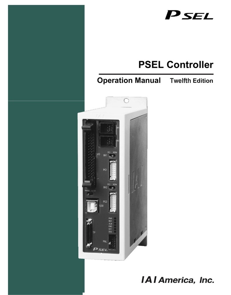
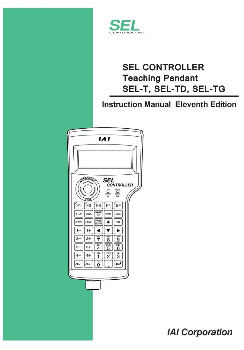
IAI X-SEL User manual

X-SEL
Teaching Pendant
Operating Manual Ver. 7.0
IAI Corporation

1. Forward...............................................................................................................
1
2. Before Use..........................................................................................................
1
3. Safety Precautions..............................................................................................
2
4. Warranty Period and Scope of Warranty.............................................................
3
5. Connection to Controller .....................................................................................
4
6. Teaching Pendant Function and Specifications ..................................................
8
6-1. Main Operation Keys and Functions ......................................................................8
7. Mode Transition Diagram..................................................................................
11
8. How to Save Data.............................................................................................
16
8-1. Set-up at Shipment with System Memory Backup Battery ...................................16
8-2. Set-up at Shipment without System Memory Backup Battery ..............................17
8-3. Caution.................................................................................................................18
9. Simple Operation Procedure.............................................................................
19
9-1. Creation of Position Data......................................................................................20
9-2. Programming........................................................................................................29
9-3. Changing Application Program.............................................................................37
10. Program Execution............................................................................................
42
10-1. Operation Confirmation ........................................................................................42
10-2. Setting of Brake Point...........................................................................................44
10-3. Monitor under Operation.......................................................................................44
11. Position Edit......................................................................................................
47
11-1. Mdi (Manual direct input)......................................................................................47
11-2. Teach (Teaching) .................................................................................................48
11-3. Example of Teaching Input...................................................................................59
11-4. Position Data: Copy or Move................................................................................64
11-5. Position Data: Clear..............................................................................................65
12. Program Edit.....................................................................................................
66
12-1. How to Input Program...........................................................................................66
12-2. Symbol Input during Program Edit........................................................................71
12-3. Single Line Comment Input..................................................................................73
12-4. Program: Copy or Move .......................................................................................75
12-5. Program: Clear.....................................................................................................76
12-6. Flash ROM Writing...............................................................................................78

13. Symbol Edit.......................................................................................................
79
13-1. Symbol Edit Items ................................................................................................79
13-2. Input Example: Symbolize Local Integer Variable................................................80
13-3. Symbol Edit Screen of Each Items.......................................................................84
13-4. Flash ROM Writing...............................................................................................88
14. Parameter Edit..................................................................................................
89
14-1. Parameter Edit Items............................................................................................89
14-2. Input Example: Edit Each-Axis Parameter............................................................90
15. Monitor..............................................................................................................
93
15-1. Monitor Items........................................................................................................93
15-2. Input Port..............................................................................................................94
15-3. Output Port...........................................................................................................94
15-4. Global Flag...........................................................................................................94
15-5. Global Variable.....................................................................................................95
15-6. Axis Status ...........................................................................................................96
15-7. System Status....................................................................................................100
15-8. Error Detail Information ......................................................................................103
15-9. Version Information ............................................................................................104
16. Controller ........................................................................................................
106
16-1. Controller Items..................................................................................................106
16-2. Flash ROM Writing.............................................................................................107
16-3. Software Reset...................................................................................................108
16-4. Error Reset.........................................................................................................108
16-5. Memory Clear.....................................................................................................109
16-6. Re-Connection ...................................................................................................109
16-7. Baud Rate Change.............................................................................................110
16-8. Safety Velocity....................................................................................................110
16-9. Driver Power Recovery Request ........................................................................ 111
16-10. Action Pause Release Request.......................................................................... 111
16-11. Driver Power Recovery Request (RPwr) and Action Pause Release Request (Ract) ..112
16-12. Absolute Reset...................................................................................................113
16-13. Procedures for Resetting Absolute-Battery Voltage-Down Warning Error..........116
*Supplement............................................................................................................
118
Synchro Specification Absolute Reset...............................................................................118
About Error Level Management........................................................................................126
X-SEL Teaching Pendant Error List (Application Part)......................................................127
X-SEL Teaching Pendant Error List (Core Part) ...............................................................130

1. Forward
Thank you very much for purchasing our X-SEL Controller Teaching Pendant. Improper usage
or mishandling may result in a product not only being unable to deliver full functions but also
produce unexpected troubles or shorten the product’s life. Please read this Manual carefully, and
operate the product properly by paying attention to its handling. When operating the Teaching
Pendant, always keep this Manual at hand and read the relevant items as required.
For the actuator and controller to be used, be sure to refer to the Instruction Manuals attached
to the products.
▪While the teaching pendant is left connected, “Effect” is valid for the safety velocity (SVel).
Therefore, the fastest velocity is under 250 mm/sec when the program is started from the
teaching pendant. To operate the controller according to the program velocity command, it is
required to change the condition to “No Effect.”
For selection of the safety velocity between Effect and No Effect, refer to “16-8. Safety Velocity.”
▪When connecting this teaching pendant to the X-SEL-Q type (global specification), emergency
stop cannot be reset.
▪The display screens must show version 1.13 or newer of the teaching pendant application
software. To confirm the version, refer to the section “15-9. Version Information.”
2. Before Use
(1) Be sure to read this Instruction Manual for proper use of this product.
(2) Part or all of this Instruction Manual may not be used or reproduced without permission.
(3) For any handling and operating methods other than those described in this Instruction
Manual, interpret them as “don’t” or “can’t.”
(4) Please take note that we shall not be liable for any effects resulting from using this Instruction
Manual.
(5) Descriptions in this Instruction Manual are subject to change due to product improvements
etc., without prior notice in the future.
1

3. Safety Precautions
(1) Use a genuine product specified by us for wiring between the actuator and X-SEL Controller.
(2) Keep out of the operating range of a machine such as an actuator while it is operating or in a
ready state (condition in which the controller’s power is ON). When using it in places where
persons may approach, fence it off.
(3) Before carrying out assembly and adjustment work or maintenance and inspection work of
the machine, be sure to disconnect the power cord. While working, display the plate specified
as such at an easy-to-read location. In addition, give special consideration to prevent third
parties from turning on the power carelessly by hauling in the power cord to the operator.
Alternatively, lock the power plug or receptacle and direct the operator to keep the key or
prepare a safety plug.
(4) When more than one operator works, advance work by determining the signal method and
checking each other’s safety. Especially, for work associated with axial movement regardless
of power ON/OFF or motor-driven/manual operation, be sure to confirm safety by calling out
to other(s) in advance.
(5) When the user (customer) extends wiring, malfunction may occur due to faulty wiring. In this
case, inspect wiring thoroughly and check it for properness before turning on the power.
2

4. Warranty Period and Scope of Warranty
The Teaching Pendant you purchased has been delivered upon completion of our strict
shipping test.
We shall warrantee this product as follows.
1. Warranty Period
The warranty term shall be either of the following terms, whichever is reached first.
▪18 months after our shipment
▪12 months after delivery to the place designated by you
2. Scope of Warranty
Where a defective condition occurs during proper use conditions and obviously under the
responsibility of the manufacturer, within the term above, we shall repair the product without
charge. However, any items that apply to the following are excluded from the warranty coverage.
▪Defects resulting from changes over time such as natural color fading of paint
▪Defects resulting from use wear of consumable parts (such as a cable)
▪Defects resulting from sensory phenomena such as generated noise that have no
functional effects
▪Defects resulting from mishandling or improper use
▪Defects resulting from an inadequacy or error in maintenance and inspection
▪Defects resulting from the use of any part other than our genuine parts
▪Defects resulting from a modification not approved by us or our dealers
▪Defects resulting from Acts of God, accident, fire, etc.
Only a delivered product shall be singly warranted, and no damage induced by the defect of
the delivery product can be warranted. For repair, transport the product to our factory.
3. Service Coverage
The cost of a delivered product does not include expenses for program creation and engineer
dispatching. Therefore, the following are charged separately even within the warranty term:
▪Maintenance and inspection
▪Technical guidance and technical training in operating instructions
▪Technical guidance and technical training on program-related matters such as program
creation
3

5. Connection to Controller
Mode Switch
M cable
K (J) Type Controller
4

Emergency
Stop Switch
Enable
Switch
Teaching Pendant Type
Selection Switch
Mode Switch
P Type Controller
▪Set the teaching pendant type selection switch to the right.
Caution
5

1. Connect actuators, I/O 24VDC power source, and system I/O to the controller first. Then
connect the cable connector of the teaching pendant to the controller’s teaching connector when
the main power supply of the controller is OFF.
2. After you flip the mode switch to MANU side, supply power to the controller.
Teaching Pendant
LCD Display
Displays the version of the teaching pendant and
moves to the following page, the mode selection
screen.
If the mode is switched to AUTO side, the teaching
pendant does not connect to the controller and the
screen on the left will be displayed. Press ESC key
and make it reconnected.
Re-connection Screen
Mode Selection Screen
Turn on the mode switch to MANU side and press
the F1 (Yes) key to execute re-connection.
This is the basic screen for all operations.
6

When the X-SEL controller J/K type executes “OPEN 1” (channel 1 shared for the teaching
pendant) within the SEL program in the MANU (manual) mode, the right of use of the serial
port channel 1 is forcefully moved to the SEL program and communication with the teaching
pendant is disconnected. The program in the controller is running. (*Error No. A5D “SCIF open
error non-auto mode”)
Afterwards, if you wish to stop movement, press ON the Emergency Stop Button (Be especially
careful during Jog operation).
*In a case prior to Ver 0.16 of controller main application.
For the controller P/Q type as well as the J/K type with the controller main application ver. 0.16
or later, the following are applied regarding OPEN of the TP port (teaching connector)
according to the servo not in use or in use:
<MANU mode, servo not in use>
Before execution of OPEN After execution of OPEN
Connection of TP port Connection to Teaching
Pendant Forced movement to SEL program connection
(Message error) Program is executing
Error occurring after OPEN command execution: Error No. A50 “SCIF open error during non-AUTO mode”
<MANU mode, servo in use>
Before execution of OPEN After execution of OPEN
Connection of TP port Connection to Teaching
Pendant Connection to Teaching Pendant
(Cold start error) Program is ending
Error occurring after OPEN command execution: Error No. E.89 “SCIF open error during non-AUTO mode (servo ON)
The channel No. of the TP port varies according to the controller’s type.
J/K type: 1 ch “OPEN 1”
P/Q type: 0 ch “OPEN 0”
Extra Caution
!
The above “Extra Caution” notes pertain to all other than “MANU mode with I/O parameter No. 90
= 2 (IAI Protocol).
7

6. Teaching Pendant Function and Specifications
6.1 Main Operation Keys and Functions
1. LCD Display
4 lines with 20 characters per line capacity display. Shows programs and motion status.
2. Emergency Stop Button
Executes emergency stop.
3. Deadman Switch (Option)
Before operating keys for Servo OFF →Servo ON, keep pressing both sides (ON) and
operating keys.
If you press only one side or not press both sides, key operation for Servo OFF →Servo ON
doesn’t work.
When servo is ON, this switch is under the state of both-side pressed, but when you release
the switch, the operation will be finished and the panel window 7 seg LED displays “dsf.”
8

4. F1 F2 F3 F4 (Function keys)
Correspond to each item in the LCD display (function key section).
5. SF key (Shift key)
If there are more than 5 selectable functions (“→“ will be displayed at right side of the function
key area), it will change the display items in the function key area.)
6. WRT key (Write key)
Transmits edit data to the controller. (Data will be saved in the memory of the controller.)
Only the data shows on the LCD display will be transmitted. (Plural position No., program step
No, etc., can’t be transmitted all together at the same time.)
7. ESC key (Escape key)
Returns to the previous status from the current status.
If you press this key during data input, the data will be cancelled.
8. BS key (Backspace key)
If you press this key during data input, clear one letter before.
At other time, clear the data where the cursor is placed.
9. ←key (Cursor backward key)
Backward the cursor. It’s reverse of Return key function.
10. 10 keys
You can input number, alphabet, and sign.
When the cursor is at any item requiring the input of characters other than “0” to “9” (such as
hexadecimal and character strings), the input mode selection is displayed in the function key
area. (Alph: alphabet symbol input, Num: numeric value input)
9

11. ↵key (Return key)
Confirms the input data and moves the cursor position forward .
12. PAGE UP · PAGE DOWN key
Increment or decrement edit and display item No. (Position No., Program No., Step No., etc.)
13. ON/OFF key
Switches servo ON or OFF of axes. (It is valid within Teac (teach) mode area)
14. HOME key
Executes homing. (It is valid in the Teac (teach) mode area with the servo ON )
15. MOVE key
Starts actuator movement or continuous movement. (It is valid in the Teac (teach) mode area
with the servo ON.)
16. STOP key
Stops actuator movement or continuous movement. (It is valid in the Teac (teach) mode area
with the servo ON.)
17. ←1 1→←2 2→←3 3→←4 4→(Jog keys)
←1 Minus direction jog movement for the 1st axis and 5th axis
1→Plus direction jog movement for the 1st axis and 5th axis
←2 Minus direction jog movement for the 2nd axis and 6th axis
2→Plus direction jog movement for the 2nd axis and 6th axis (It’s valid in the Teac (teach)
mode area with the servo
ON
←3 Minus direction jog movement for the 3rd axis
3→Plus direction jog movement for the 3rd axis
←4 Minus direction jog movement for the 4th axis
4→Plus direction jog movement for the 4th axis
▪Such jog actions with the JOG button are also valid for any not-homed axes. However,
coordinate values in this case have no meaning. Therefore, be extremely careful about
interference with the stroke end.
▪If jog operation is performed to the axis in action under the operation-button-acceptable
condition, the operation of the applicable axis is aborted when the JOG operation button is
turned OFF. (The next operation starts, if any.)
Caution
10

7. Mode Transition Diagram
(User-specified
output port
monitor
)
(User-specified
output port
monitor
)
* TP application Ver. 1.05 or later only.
The above are effective only for the
5-axis/6-axis spec. controllers.
(Axis No.
display
chan
g
e
)
(Axis No.
display
chan
g
e
)
* After writing data with [WRT],
move to the next position
Position data
input
(Continuous
movement)
(Jog velocity)
(Output
monitor)
(Input
monitor)
(Continuous
movement)
(Jog velocity)
(Output
monitor)
(Velocity data)
(Input
monitor)
(Cancel)
(Data import)
(Display
change)
(Clear)
(Data import)
(Display
change)
Cursor
position data
Cursor
position No.
(Velocity
input)
Function key
(Copy/Move)
(Clear)
(Teach)
Select position No. and
press return Function key
(Write to
Flash ROM)
“Yes” or “No”
* When escaping the mode
with [ESC], check whether to
write to Flash ROM.
* After writing data with [WRT],
move to the next position
Manual input)
Position data
input
(Position) (
Select position No. and
press return
Function keyFunction keyFunction key
Mode
selection
Communications
established
Power ON
11

Select the
program No.
and press retur Select the step No.
and press return
Function key n
Step data
input
(Program) (Modify)
* After writing data with [WRT], move to the
next step
* Move to the symbol edit mode with “Sym”
(Copy/Move)
(Clear)
Select the symbol type with the function key
Symbol/
Definition
value input
(Symbol)
* After writing data with [WRT], move to
the next edit No.
Select the parameter type with the function key
Parameter
input
(Parameter)
* After writing data with [WRT], move to
the next edit No.
Select the program No.
and press return
Function key Function key
Move to the mode according to the
current condition
(Program
operation) (Current
position)
(Continuous
execution) (Step
execution
)
(Execution)
Step
execution
completed
(Local flag) Function key
(Execution
stop
)
(Suspend step)
(Local
variable) (Integer
variable)
(Program
error display) (Real
variable)
* Only during
program stop
(String
variable)
(Task status
display)
12

Function key
(Monitor) (Input port)
(Output port)
(Global flag)
Function key
(Global
variable) (Integer
variable)
(Real
variable)
(String
variable)
Function key
(Current
position)
(Axis status)
(Servo status)
(Sensor input
status)
(Encoder
status)
(Axis-related
error)
13

Function key
(System
status
)
(System
mode)
(System
error)
(System
status 1)
(System
status 2)
(System
status 3)
(System
status 4)
(Error list)
Function key
(Version) (CTL main)
(Driver)
(Teaching
pendant)
(P/Q type only)
(Mount SIO)
(P/Q type only)
(P/Q type only)
(Control
constant)
14

Function key
(Flash ROM
writing)
(Controller)
(Software
reset)
(Error reset)
Function key
(Memory
clear) (Global
variable)
(Re-connect)
(Baud rate
change)
(Driver power
recovery request)
(Action pause
release request)
(
A
bsolute
reset)
* You need to input the password to change setting, when manual operation classification
parameter=edit/start up selection (with password).
(Velocity effect
select)
* Displayed only when manual operation classification parameter=edit/start up selection (with
password).
* You will need to input the password to change setting.
(Refer to the Supplement and section 8 “Manual Operation” in the X-SEL Controller Instruction
Manual.)
(PIO start
prohibit select)
▪Flow at Error Occurrence
Error occurs
Mode under
operation Message
display
Serious error
Minor error
Re-connection
mode
15

8. How to Save Data
Since the X-SEL Controller adopts flash memory, there is a storage area by battery backup and a
storage area by flash memory according to the data to be stored.
In addition, even if data is transferred from the PC software or Teaching Pendant, the data is only
to be written in memory as shown in the chart below and the data is erased by power-off or
controller reset.
To ensure data storage, write the data you want to store in flash memory.
8-1. Set-up at Shipment with System Memory Backup Battery
(Other parameter No. 20=2 (System memory backup battery equipped))
Edit data with PC or
Teaching Pendant
Save the data during the
power is on and delete
the data by reset Save data even after the power OFF
Flash write
Program
parameter
(content 1)
Symbol
Flash
memory
Memory
Transmit Reset read
Transmit
Slave card
parameter
(content 2) Memory
Transmit Reset read
Transmit
* Encoder
parameter Memory * Encoder
Transmit Reset read
Position Battery
backup
memory
Flash
memory
Transmit Flash write
Battery
backup
memory
SEL global data
(content 3)
Error list Transmit
* Encoder parameters are not stored within the controller but in the EEPROM of the actuator’s
encoder itself. They are read into the controller at power-on or software-reset time.
16

Since the program, parameter, and symbol will be read from flash memory at restart time, the
data in memory becomes the original data before editing unless the data is written in flash
memory.
The controller always operates according to the data in memory (within the dotted box) excluding
parameters.
Content 1: Parameters excluding content 2 below and encoder parameter
Content 2: Driver card, IO slot card (electric power type card) parameter
Content 3: Flag, Variable, and String
8-2. Set-up at Shipment without System Memory Backup Battery
Other parameter No.20=0 (System memory backup battery unequipped)
Edit data with PC or
Teaching Pendant
Save the data during the
power is on and delete
the data by reset Save data even after the power OFF
Program
Parameter
(content 1)
Symbol
Position
Flash write Flash
memory
Memory
Transmit
Reset read
Transmit
Slave card
parameter
(content 2) Memory
Transmit Reset read
Transfer
* Encoder
parameter * Encoder
Transmit Memory Reset read
SEL global data
(content 3)
Error list Memory
Transmit
Since the program, parameter, symbol, and position will be read from flash memory at restart time,
the data in memory becomes the original data before editing unless the data is written in flash
memory.
The controller always operates according to the data in memory (within the dotted box) excluding
parameters.
Note: SEL global data can’t be saved without the backup battery.
17
Other manuals for X-SEL
5
Table of contents
Other IAI Controllers manuals