Sensia True-Cut R Series User manual
Manual No. 20165019, Rev. A
Clif Mock
True-Cut R-Series
Sample Receptacles
User Manual

Table of Contents
General Description...................................................................................................1
Installation and Operation..........................................................................................2
Maintenance ..............................................................................................................3
Trouble Shooting........................................................................................................4
Pressure Venting....................................................................................................4
Plugging.................................................................................................................4
© 2004 NuFlo Technologies, Inc. All information contained in this publication is
confidential and proprietary property of NuFlo Technologies, Inc. Any reproduction
or use of these instructions, drawings, or photographs without the express written
permission of an officer of NuFlo Technologies, Inc. is forbidden.
All Rights Reserved.
Printed in the United States of America.
Manual No. 20165019, Rev. A
July 2004
July 2004 1 M20-3 Mixing System
General Description
The R-Series receptacle provides for the safe, convenient storage and transportation of
samples collected from the customer's pipeline. When an R-Series receptacle is used in
combination with the Clif Mock M20-3 Mixing System, a sample can be collected,
transported to a testing laboratory, and mixed in the same receptacle. The 304 stainless steel
(316 optional) tank assembly, which is rated for 100-psi maximum pressure, inserts directly
into the M20-3 Mixing System and serves as a mixing reservoir. The ability to collect,
transport, and mix a sample in one reservoir eliminates water loss and helps to prevent light
ends during transfers.
In addition to allowing direct hook-up to the sample probe, the R-Series receptacle is equipped with a
carrying handle for transporting the contents to a laboratory for analysis. The R-Series receptacle is
avaialble in three sizes (Figure 1):
•R4-4 (1-gallon capacity)
•R8-4 (2-gallon capacity)
•R20-4 (5-gallon capacity)
Figure 1—R-Series portable receptacles (from left): R20-4 (5 gallons), R8-4 (2 gallons),
and R4-4 (1 gallon).

M20-3 Mixing System 2 July 2004
Components of the R-Series receptacles include:
•a 316 stainless steel pressure-relief valve fixed at 5 psi
•a 316 stainless steel vacuum relief valve fixed at 1 psi
•a 316 stainless steel ¼-in. MNPT ×¼-in. MNPT manual vent valve
•a sample inlet ½-in. FQD nozzle
•a 0-to-60 back MTD 1/8-in. NPT pressure gauge
•a high level shut-off assembly to prevent overfilling
•a ¾-in. FQD nozzle (mixing discharge)
•a ¾-in. FQD nozzle (suction)
Installation and Operation
Use the following procedure to collect and transport a sample from the field to a laboratory.
1. Connect the sample fill line from the sample probe to the ½-in. sample inlet connection at
the top of the receptacle via a shut-off valve (supplied by customer).
2. Start the drive motor on the sample probe.
3. After the sample is taken, stop the drive motor on the sample probe.
4. Close the shut-off valve.
5. Uncouple the fill line from the receptacle and cover the inlet with a dust cover.
6. Transport the receptacle to the laboratory.
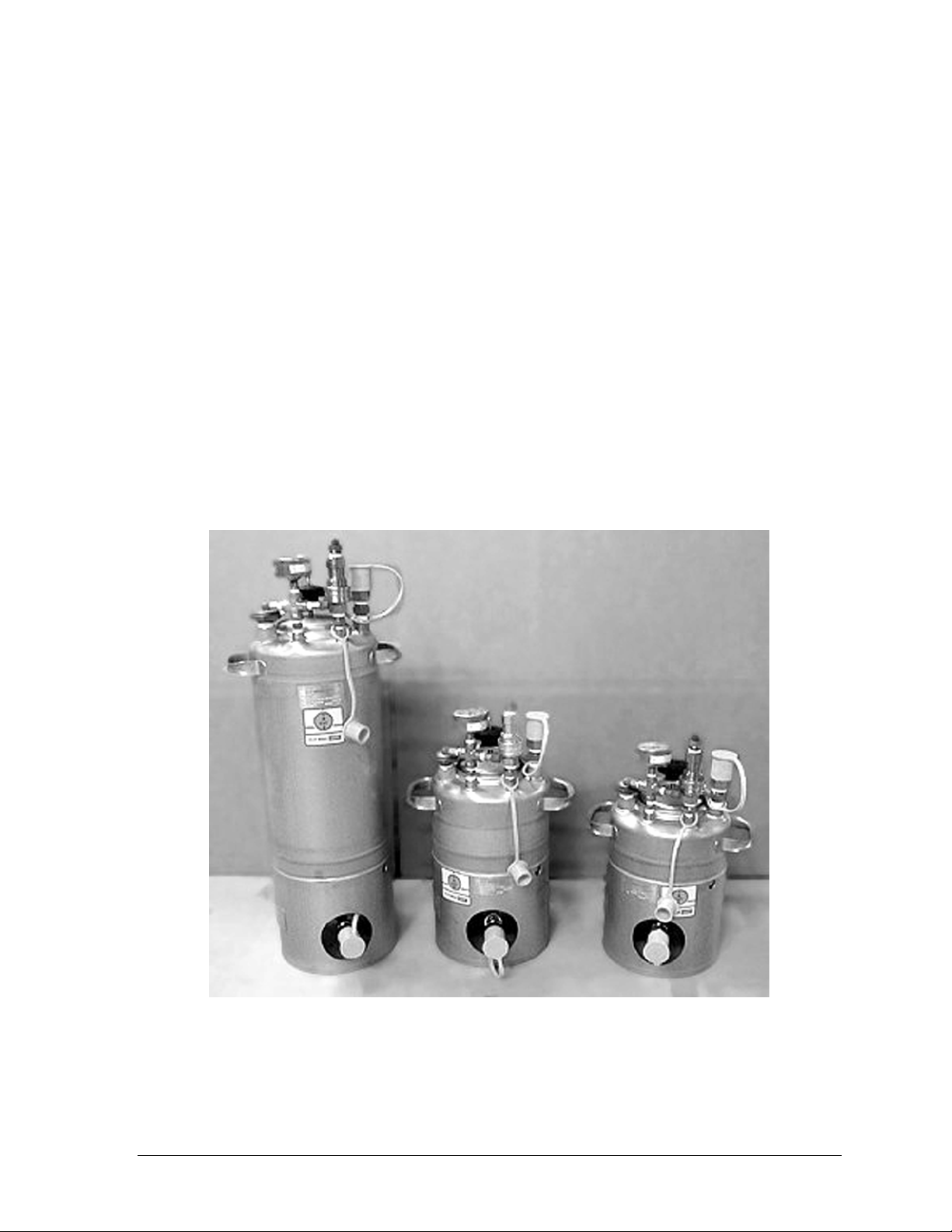
7. Empty the sample from the receptacle via the ¾-in. FQD connection at the base of the
receptacle, or connect the receptacle to the M20-3 mixing system (Figure 2). Detailed
instructions for mixing a sample are provided in the M20-3 Mixing System manual.
July 2004 3 M20-3 Mixing System
Figure 2—Hose connections for mixing a sample inside the receptacle with the M20-3
mixing system
Maintenance
Perform the following maintenance after each use of the R-Series receptacle.
1. After all the sampled liquid is withdrawn from the receptacle, clean the receptacle tank,
the inlet, and the discharge with a solvent to prevent contamination of subsequent
samples.
2. After the sample has been drained from the receptacle, inject the cleaning solvent through
the fill line to clean the line, the sample inlet, and the high level shut-off.
3. Remove the lid from the receptacle. Taking care not to damage the high level shut-off
assembly, wash the inside of the receptacle with the solvent. Flush the solvent through
the 3/4-in. FQD connection at the base of the receptacle.
4. Dry the inside of the tank.

M20-3 Mixing System 4 July 2004
Trouble Shooting
Pressure Venting
If the high level shut-off has stopped the flow to the receptacle and the pressure gauge does
not return to "0" psi when the manual valve is opened, use extreme caution in opening the
lid. The valve may be plugged or the gauge may be defective, and the receptacle may still be
pressurized.
•If pressure escapes from the receptacle, the manual vent valve is faulty and must be
replaced.
•If there is no noticeable pressure escape, the pressure gauge is faulty and must be
replaced.
Plugging
If the sample from the pipeline is not accumulating in the receptacle, check the following
areas for possible plugging.
•Sample Probe. If there is no sample discharge when the fill line is removed from the
sample probe, remove the probe and clean it. Refer to the repair procedure for the
appropriate sample probe.
•Fill Line. If there is no sample discharge when the fill line is disconnected from the
quick disconnect coupling, remove the fill line from the sample probe. If there is
sample discharge at this point, the fill line is plugged; take steps to clean or replace it.
•Sample Inlet Nozzle. If there is no sample discharge when the quick disconnect
assembly is removed from the receptacle lid, disconnect the fill line from the
coupling. If there is sample discharge at this point, the sample inlet nozzle (quick
disconnect nose and/or coupling) is plugged; take steps to clean or replace it.
•High Level Shut-Off. Stop the drive motor on the sample probe and open the manual
vent valve to release pressure. Detach the ½ in. quick disconnect nose from the
receptacle lid and unscrew the lid from the tank. Reconnect the ½-in. quick
disconnect nose to the receptacle lid. Start the sample probe drive motor and watch for
sample discharge.
If the sample is not being discharged, remove the quick disconnect coupling, unscrew the
nose from the receptacle lid, and insert the nose back into the quick disconnect coupling. If
sample is discharged from the nose, disassemble the high level shut-off assembly and clean it.
July 2004 5 M20-3 Mixing System
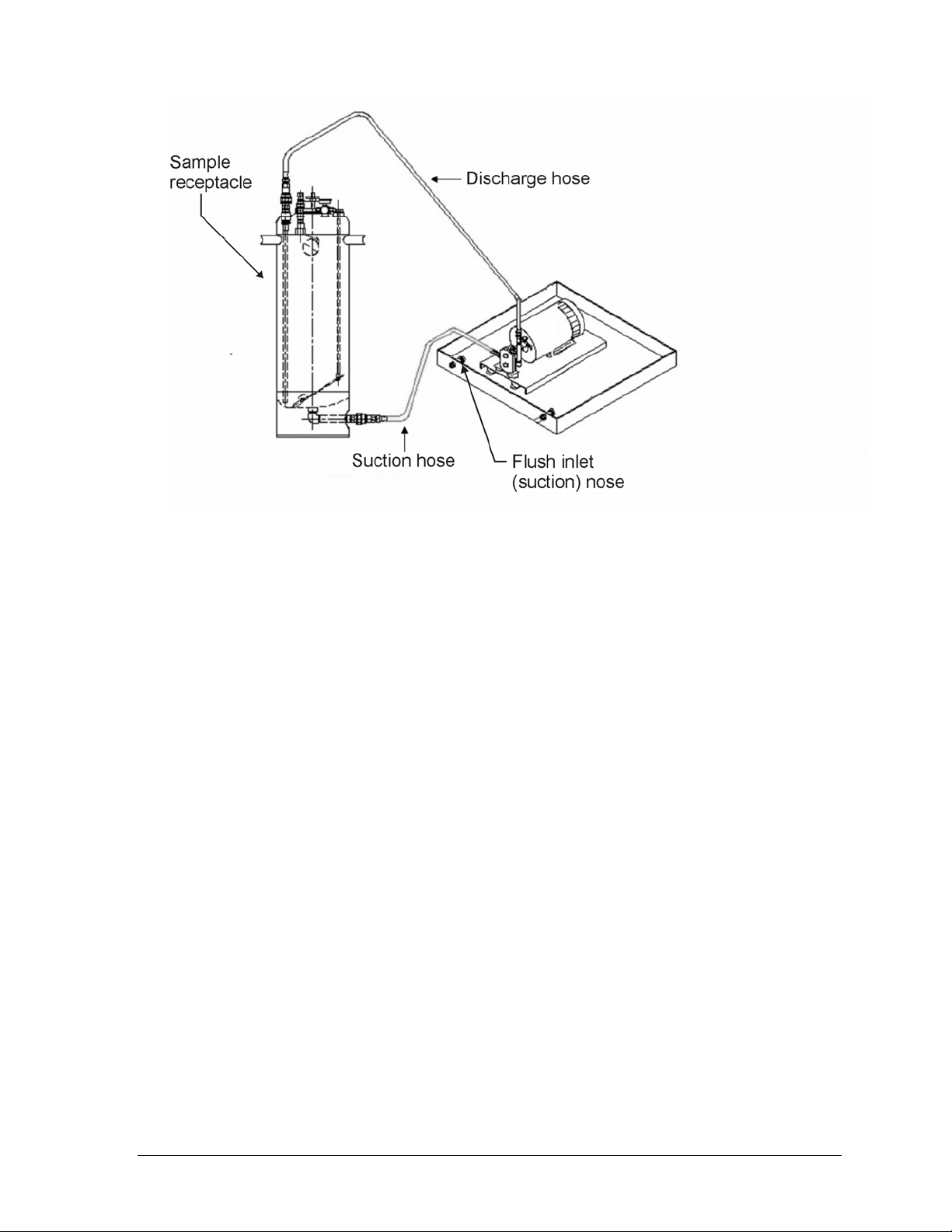
BILL OF MATERIALS
ITEM QTY PART NO. DESCRIPTION
1 2 50142310075 ¾” Nose, QD
50142733002 R4-4 Tank, 304 SS
50142381872 R8-4 Tank, 304 SS
2 1
(select from
3 sizes) 50142381770 R20-4 Tank, 304SS
3 1 50142302204 Downcomer, Tube 1.2”, SS
4 1 50142311046 High Level Shut-off
5 1 50142310079 ½” Coupler, QD
6 Vacuum Lid
7 1 50142381040 Gauge, 0-60 psi, SS
8 1 50142200334 Pressure Relief Valve, 5 psi
9 1 50142303543 Vacuum Relief Valve, 1 psi
10 1 50142310029 Level Gauge

M20-3 Mixing System 6 July 2004

WARRANTY - LIMITATION OF LIABILITY: Seller warrants only title to the products,
software, supplies and materials and that, except as to software, the same are free from
defects in workmanship and materials for a period of one (1) year from the date of delivery.
Seller does not warranty that software is free from error or that software will run in an
uninterrupted fashion. Seller provides all software "as is". THERE ARE NO WARRANTIES,
EXPRESS OR IMPLIED, OF MERCHANTABILITY, FITNESS FOR A PARTICULAR
PURPOSE, OR OTHERWISE WHICH EXTEND BEYOND THOSE STATED IN THE
IMMEDIATELY PRECEDING SENTENCE. Seller's liability and Buyer's exclusive remedy in
any case of action (whether in contract, tort, breach of warranty or otherwise) arising out of
the sale or use of any products, software, supplies, or materials is expressly limited to the
replacement of such products, software, supplies, or materials on their return to Seller or, at
Seller's option, to the allowance to the customer of credit for the cost of such items. In no
event shall Seller be liable for special, incidental, indirect, punitive or consequential damages.
Seller does not warrant in any way products, software, supplies and materials not
manufactured by Seller, and such will be sold only with the warranties that are given by the
manufacturer thereof. Seller will pass only through to its purchaser of such items the
warranty granted to it by the manufacturer.

Table of contents


