Icom COMMUNICATION RECEIVER IC PCR100 User manual

INSTRUCTION MANUAL
This device complies with Part 15 of the FCC rules.Operation is sub-
ject to the following two conditions: (1) This device may not cause
harmful interference, and (2) this device must accept any interference
received, including interference that may cause undesired operation.
iPCR100
COMMUNICATIONS RECEIVER FOR COMPUTER

i
IMPORTANT
READ ALL INSTRUCTIONS carefully and com-
pletely before using the receiver.
SAVE THIS INSTRUCTION MANUAL— This
instruction manual contains important operating instructions
for the IC-PCR100 COMMUNICATIONS RECEIVER FOR
COMPUTER.
USEantenna(s), such as a well-matched 50 Ωantenna and
feedline. For radio communications, the antenna is of critical
importance, along with sensitivity.
SYSTEM REQUIREMENTS
•IBM PC/AT compatible computer
•An RS-232C serial port (38400 bps or faster)
•Microsoft®Windows®95 or Microsoft®Windows®98
•Intel i486DX4 processor or faster (Pentium®100 MHz or
faster recommended)
•At least 16 MB RAM
•At least 10 MB of hard disk space
•At least 640 ×480 pixel display (800 ×600 pixel display rec-
ommended)
OPERATING THEORY
Electromagnetic radiation which has frequencies of 20,000
Hz (20 kHz*) and above is called radio frequency (RF) energy
because it is useful in radio transmissions. The IC-PCR100
receives RF energy from 0.5 MHz* to 1300 MHz and converts
it into audio frequency (AF) energy which in turn actuates a
loudspeaker to create sound waves.AF energy is in the range
of 20 to 20,000 Hz.
*kHz is an abbreviation of kilohertz or 1000 hertz, MHz is abbrevia-
tion of megahertz or 1,000,000 hertz, where hertz is a unit of fre-
quency.
OPERATING NOTES
The IC-PCR100 may receive its own oscillated frequency, re-
sulting in no reception or only noise reception, on some fre-
quencies.
The IC-PCR100 may receive interference from extremely
strong signals on different frequencies or when using an ex-
ternal high-gain antenna.
Versions of the IC-PCR100 which display “CE” on the serial num-
ber seal, comply with the essential requirements of the
89/336/EEC directive for Electromagnetic Compatibility.

CAUTIONS
RWARNING! NEVER connect the receiver to an AC
outlet. This may pose a fire hazard or result in an electric
shock.
NEVER connect other than the specified AC adapter to the
receiver. This connection will ruin the receiver.
NEVER connect the receiver to a power source of more
than 16 V DC such as a 24 V battery. This connection will ruin
the receiver.
NEVER expose the receiver to rain, snow or any liquids.
DO NOT use or place the receiver in areas with tempera-
tures below 0°C (+32°F) or above +50°C (+122°F) or, in areas
subject to direct sunlight.
AVOID placing the receiver in excessively dusty environ-
ments.
AVOID the use of chemical agents such as benzine or al-
cohol when cleaning, as they damage the receiver surfaces.
Place unit in a secure place to avoid inadvertent use by children.
For U.S.A. only (FCC information)
CAUTION: Changes or modifications not expressly ap-
proved by Icom Inc. could void the user’s authority to operate
this receiver.
Class B digital device users
This equipment has been tested and found to comply with the limits
for Class B digital devices, pursuant to Part 15 of the FCC Rules.
These limits are designed to provide reasonable protection against
harmful interference in a residential installation. This equipment gen-
erates, uses and can radiate radio frequency energy and, if not in-
stalled and used in accordance with the instruction manual, may
cause harmful interference to radio communications. However, there
is no guarantee that interference will not occur in a particular installa-
tion. If this equipment does cause harmful interference to radio or
television reception, which can be determined by turning the equip-
ment off and on, the user is encouraged to try to correct the interfer-
ence by one or more of the following measures:
- Reorient or relocate the receiving antenna.
- Increase the separation between the equipment and receiver.
- Connect the equipment into an outlet on a circuit different from that
to which the receiver is connected.
- Consult the dealer or an experienced radio/TV technician for help.
For Canada only
Operation is subject to the following two conditions: (1) this device
may not cause interference, and (2) this device must accept any in-
terference, including interference that may cause undesired opera-
tion of the device. ii
IBM is registered trademark of International Business Machines Corporation in
the U.S.A.and other countries.Microsoft®and Windows®are registered trade-
marks of Microsoft Corporation in the U.S.A and other countries. Screen shots
produced with permission from Microsoft Corporation. All other products or
brands are registered trademarks or trademarks of their respective holders.

iii
IMPORTANT ...................................... i
SYSTEM REQUIREMENTS .............. i
OPERATING THEORY ....................... i
OPERATING NOTES ......................... i
CAUTIONS ........................................ ii
TABLE OF CONTENTS .................... iii
1 INSTALLATION ...................... 1–5
■Hardware installation ................ 1
■Antenna installation .................. 2
■Grounding ................................. 2
■AF output level selection ........... 3
■Software installation ................. 4
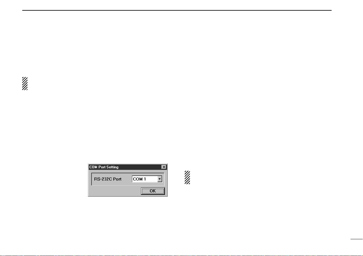
■RS-232C port setting ................ 5
■Mouse property setting ............. 5
2 PANEL DESCRIPTION ........ 6–15
■Multi-function receiver screen ... 6
■Function display ...................... 10
■Simple function receiver
screen ..................................... 12
■Function controller screen ...... 14
■Simple function receiver sub
screens ................................... 15
3 BASIC OPERATION ........... 16–21
■Receiving ................................ 16
■Setting a frequency ................. 17
■Setting a tuning step ............... 18
■Receive mode selection ......... 18
■Automatic mode selection ...... 19
■Setting squelch level ............... 20
■IF filter selection ..................... 20
■Attenuator function ................. 21
■Automatic noise limiter ........... 21
4 MEMORY CHANNELS ....... 22–25
■General ................................... 22
■Saving memory channels........ 22
■Selecting a memory channel... 23
■Memory channel
programming .......................... 24
■Clearing a memory channel .... 24
■Editing the memory list ........... 25
5 SCAN OPERATION ............ 26–33
■Scan types .............................. 26
■Programmed scan .................. 27
■Setting scan edges ................. 28
■Auto memory write scan ......... 29
■Memory scan .......................... 30
■Versatile memory scan ........... 31
■Scan resume condition ........... 32
■Scan speed setting.................. 33
6 BAND SCOPE .................... 34–35
■Operation ................................ 34
■Changing the automatic
sweep step limit ...................... 35
7
TONE SQUELCH OPERATION
... 36
8 TROUBLESHOOTING .............. 37
9
SPECIFICATIONS AND SUPPLIED
ACCESSORIES
.................... 38–39
■Specifications ......................... 38
■Supplied accessories .............. 39
TABLE OF CONTENTS

1
1
INSTALLATION
■Hardware installation
Refer to the diagram below for connections.
Ground
Supplied antenna
to an AC adapter
to an
RS-232C port
External speaker
Personal computer

2
1INSTALLATION
■Antenna installation
Antennas play a very important role in receiver operation.
Connecting a poor quality antenna to the IC-PCR100 will re-
sult in less than optimum performance.
Select antenna(s), such as a well-matched 50 Ωantenna and
feedline. 1.5:1 ofVoltage Standing Wave Ratio (VSWR) is rec-
ommended for a desired band. Of course, the antenna line
should be a coaxial cable.
CAUTION: Protect your receiver from lightning by
using a lightning arrestor.
NOTE: The supplied antenna is a simple plain antenna which
may not obtain indicated specifications. To obtain maximum
performance from the IC-PCR100, you must purchase an ex-
ternal wide band antenna such as an optional Icom AH-7000
(25–1300 MHz), etc.
Contact your nearest Icom Dealer or Service Center for re-
garding optimum antenna locations.
The antenna connector type is BNC, so an adapter may be
necessary to connect an optional antenna.
■Grounding
RWARNING: NEVER use a gas pipe or electrical
conduit pipe for grounding.
To prevent accidents involving electricity and interference
from computers, ground the receiver through the GROUND
terminal on the rear panel.
For best results, connect a heavy gauge cable to a water pipe
or long, earth-sunk copper rod. Make the distance between
the [GND] terminal and ground as short as possible.

3
1
INSTALLATION
■AF output level selection
The received audio can be input into your computer via the
sound card.
Before inputting the received audio into the [LINE IN] con-
nector (connector name depends on your sound card), the
output level of the [EXT-SP] must be set properly. Perform as
follows:
CAUTION: Setting ‘STEREO’and connecting a 2-con-
ductor plug cause a short-circuit. This may damage the
audio power amplifier.
DMulti-function receiver screen
qSelect ‘EXT-Speaker’in the option menu to bring up the
[EXT-Speaker Setting] dialog box.
wSelect the plug type as shown below.
•“STEREO”for 3-conductor stereo plug.
•“MONO”for 2-conductor
monaural plug.
eSelect the output level
as shown at right.
•“SP”for internal or exter-
nal speaker.
•“LINE”for PC sound
card or headphones.
rConnect an appropriate cable between IC-PCR100 and
PC.
•Use a 3-conductor stereo plug for connecting to the receiver.
DSimple function receiver screen
qRight-click* the frequency indication to display shortcut
menu and select‘EXT-Speaker’in the Option menu to bring
up the [EXT-Speaker Setting] dialog box.
* When the mouse property is set for right-handed.
wSelect the plug type.
•“STEREO”for 3-conductor stereo plug.
•“MONO”for 2-conductor monaural plug.
eSelect the output level.
•“SP”for internal or external speaker.
•“LINE”for PC sound card or headphones.
rConnect an appropriate cable between IC-PCR100 and
PC.
[EXT-SP]
to [LINE IN]
(depends on
your sound card)

4
1INSTALLATION
■Software installation
NOTE: Before using the program, make a backup copy of
the original disk. After making a backup copy, keep the
original disk in a safe place.
NOTE: Depending on the Windows®system files, the PC
may require rebooting. In this case, repeat the installation
from the beginning.
DInstallation
qBoot up Windows.
•Quit all applications when windows is running.
wInsert the backup disk 1 into the appropriate floppy drive.
eSelect ‘Run’from the [Start] menu.
rType the setup program name with full path name, then
press the [Enter] key. (A:\SETUP [Enter])
tFollowing dialog appears. Follow the prompts.
yProgram group ‘IC-PCR100’appears in the ‘Programs’
folder of the [Start] menu.
DSoftware update information
Software update information will be available at the Icom
America home page:
http://www.icomamerica.com/

5
1
INSTALLATION
■RS-232C port setting
‘COM Port Error’or‘Communication failed’dialog box appears
when the RS-232C serial port is not set correctly.
NOTE: When launching the program for the first time, this
setting dialog appears for setting the RS-232C serial port.
DMulti-function receiver screen
qBefore launching the program, make sure the IC-PCR100
interface unit is connected correctly.
wLaunch the IC-PCR100 software.
eClick the [POWER] button in the tool bar or select ‘Power
OFF’in the File menu to temporarily pause the program.
rClick the [PORT] button or select ‘COM Port’in the Option
menu to bring up the [COM Port Setting] dialog box.
tClick the desired
COM port number to
choose it.
yClick the [OK] button.
DSimple function receiver screen
qBefore launching the program, make sure the IC-PCR100
interface unit is connected correctly.
wLaunch the IC-PCR100 software.
eClick the [POWER] button to temporarily pause the pro-
gram.
rRight-click* the frequency indication to display shortcut
menu and select ‘COM Port’in the Option menu to bring
up the [COM Port Setting] dialog box.
* When the mouse property is set for right-handed.
tClick the desired COM port number to choose it.
yClick the [OK] button.
■Mouse property setting
The IC-PCR100 uses left and right buttons to rotate a control
knob on the multi-function receiver screen or to call up the
shortcut menu from the simple function receiver screen. De-
pending on the mouse property setting of the control panel,
main and sub mouse button functions are alternated.
In this instruction manual, the operation is described with
setting for right-handed (Windows®default setting).
DSetting the button configuration
qSelect ‘Settings’from the [Start] menu and click ‘Control
Panel.’
wOpen the mouse control panel.
eSelect the button configuration to right- or left-handed.
rClick [OK] to set and exit the control panel.

■
Multi-function receiver screen
qPOWER BUTTON [POWER]
Toggles the receiver power ON and OFF.
wFILE MENU [File]
Used for turning the software on/off, saving memory chan-
nel contents or quitting the program, etc.
eVIEW MENU [View]
Used for showing/hiding the memory list screen/tool bar or
selecting the simple function receiver screen.
rSIMPLE FUNCTION RECEIVER BUTTON
Push to selects the simple function receiver screen.
tBANK MENU [BANK]
Used for selecting the memory bank.
yMEMORY LIST SCREEN BUTTON
Push to display or to hide the memory list screen.
uEXTERNAL SPEAKER SETTING BUTTON (p. 3)
Push to display the external speaker setting dialog box.
iOPTION MENU [Option]
Used for displaying the external speaker setting dialog box
or COM port setting dialog box.
oCOM PORT SETTING BUTTON (p. 5)
Push to display the COM port setting dialog box.
!0 EXIT BUTTON
Push to quit and exit this software.
6
2PANEL DESCRIPTION
Function display
quw erty io!0 !1
!2 !3 !7 !8 !9 @0 @1 @2 @3!4 !5 !6

7
2
PANEL DESCRIPTION
!1 CLOSE BUTTON
Push to quit and exit this software.
!2 ATTENUATOR BUTTON [ATT] (p. 21)
Push to turn the 20 dB attenuator on and off.
!3 VOLUME CONTROL [VOLUME] (p. 16)
Adjusts the audio output.
•Right-click* to increase the volume level; left-click* to decrease
the volume level.
!4 AUTOMATIC NOISE LIMITER BUTTON [ANL] (p. 21)
Push to turn the automatic noise limiter for receiving AM
signals on and off.
!5 SQUELCH CONTROL [SQUELCH] (p. 20)
Adjusts the squelch threshold level.The squelch removes
noise output from the speaker (closed condition) when no
signal is received.
•Right-click* to increase the squelch level; left-click* to decrease
the squelch level.
!6 TONE SQUELCH BUTTON [T-SQL] (p. 36)
Push to show or hide the [TONE SQUELCH] dialog box for
setting tone squelch frequencies.
!7
RECEIVE MODE BUTTONS [FM], [WFM], [AM], [AUT-M]
(pgs. 18, 19)
Select a receive mode. The [AUT-M] button, automatic
mode, selects a previously programmed receive mode au-
tomatically depending on a receive frequency.
!8 SCAN SPEED CONTROL [SPEED] (p. 33)
Sets the speed at which scans search through frequen-
cies/memories for signals.
•Right-click* to increase the speed; left-click* to decrease the
speed.
!9 SCAN DELAY TIME CONTROL [DELAY] (p. 32)
Sets the period in which a scan pauses after receiving a
signal.
•Right-click* to increase the period; left-click* to decrease the pe-
riod.
@0 TUNING STEP UP/DOWN BUTTONS [TSJ]/[TSK]
(p. 18)
Push to select the tuning steps.
@1 TUNING DIAL (p. 17)
Push to set the receive frequency with the selected tuning
step.
•Right-click* to increase the frequency; left-click* to decrease the
frequency.
@2 MEMORY BANK UP/DOWN BUTTONS
[BANK∧]/[BANK∨](p. 23)
Push to select the memory bank.
@3 MEMORY CHANNEL UP/DOWN BUTTONS
[CH∧]/[CH∨](p. 23)
Push to select the memory channel.
* When the mouse property is set for right-handed.

8
2PANEL DESCRIPTION
@4 KEYPAD [0]–[9], [•], [CE] (p. 17)
➥[0] to [9] are used to input a receive frequency or mem-
ory channel directly.
➥[•] (Decimal) button is used to set the MHz digit when in-
putting a frequency.
➥[CE] (Clear) button is used to clear mistakes while in-
putting a receive frequency or memory channel.
@5 IF FILTER BUTTONS [NAR]/[WID] (p. 20)
Push to change the IF filter in use. The [WID] button se-
lects a wider filter, the [NAR] button selects a narrower fil-
ter.
•Usable IF filters vary according to receive mode.
@6 SCAN STOP BUTTON [STOP] (p. 26)
Push to cancel scan operation.
@7 PROGRAMMED SCAN BUTTON [PROG] (p. 27)
Push to start/stop programmed scan.
•“PROG”flashes while scanning.
@8 SPAN +/–BUTTONS [SPAN+]/[SPAN–](p. 34)
Push to select one of four levels for the band scope fre-
quency span.
@9 AUTO MEMORY WRITE SCAN BUTTON [AUTO] (p. 29)
Push to start/stop auto memory write scan.
•“AUTO”flashes while scanning.
@4
@5 @6 @7 @8 @9 #1 #2 #3 #6 #7#4 #5#0

9
2
PANEL DESCRIPTION
#0 SWEEP START/PAUSE BUTTON [ss/❙❙](p. 34)
Push to start/pause the band scope (sweep) function
which is used to observe signal conditions around the re-
ceive frequency.
NOTE: While using the band scope function, audio is
NOT output. To monitor the frequency, push [s/❙❙] to
pause the function, or push [■] to cancel the function.
#1 MEMORY SCAN BUTTON [MEMO] (p. 30)
Push to start/stop any of the memory scans.
•“MEMO”flashes while scanning.
#2 SWEEP STOP BUTTON [■](p. 34)
Push to stop a band scope (sweep) function.
#3 SET BUTTON [SET]
Push to show the setting screen used to adjust settings for
scan functions, the band scope function and the automatic
mode function.

10
2PANEL DESCRIPTION
■Function display
qMEMORY BANK INDICATOR (p. 23)
Indicates the memory bank number (and its name if it has
one) being received.
wMEMORY CHANNEL INDICATOR (p. 23)
Indicates the memory channel number (and its name if it
has one) being received.
•The name darkens when the receive frequency changes from the
stored one.
eFREQUENCY INDICATION (p. 17)
Indicates the receive frequency and data as it is being
input such as memory channel numbers, etc.
rS (SIGNAL) METER (pgs. 16, 20)
Indicates the receive signal strength. Also indicates the
S-meter squelch receive level set via the [SQUELCH] con-
trol.
tBAND SCOPE PAUSE INDICATOR [PAUSE] (p. 34)
Appears when pausing the band scope.
yBUSY INDICATOR [BUSY]
Appears when receiving a signal or when signal noise
opens the squelch.
uRECEIVE MODE INDICATORS (p. 18)
Indicate the current receive mode.
•“WFM”lights in red when receiving a stereo broadcast program.
iTUNING STEP INDICATOR (p. 18)
This is the frequency increment used when selecting a fre-
quency using the tuning dial and when searching for sig-
nals using a scan function.
oIF FILTER INDICATOR (p. 20)
Indicates the selected IF filter and signal passband width.
!0 ATTENUATOR INDICATOR [ATT] (p. 21)
Appears when the attenuator function is on.
e
qw
!2 !3 !7!4 !4!5 !6
ur
t
y
i
o
!0 !1

11
2
PANEL DESCRIPTION
!1 AUTOMATIC NOISE LIMITER INDICATOR [ANL] (p. 21)
Appears when the automatic noise limiter is on.
!2 TONE SQUELCH INDICATOR [T-SQL] (p. 36)
Appears when the tone squelch is on.
!3 AUTOMATIC MODE INDICATOR [AUT-M] (p. 19)
Appears when the automatic mode function is on.
!4 MAXIMUM FREQUENCY SPAN INDICATORS (p. 34)
➥Indicate the upper and lower observable frequency limits
around a receive frequency.
➥In the diagram, the upper and lower limits are +100 kHz
and –100 kHz.
!5 FREQUENCY SPAN INDICATION (p. 34)
Indicates the frequency span selected with the [SPAN–] or
[SPAN+] button.
!6 CENTER FREQUENCY INDICATOR (p. 34)
Indicates the center frequency of the frequency span; this
is for the currently received frequency.
!7 SWEEP STEP INDICATOR (p. 34)
Indicates band scope sweep step.
!8 LIMIT INDICATOR (p. 35)
➥Indicates when the tuning step is greater than the auto-
matic sweep step setting.
➥In the diagram, the tuning step is greater than the auto-
matic sweep step setting and the tuning step (TS) and
the sweep step width are not the same.

12
2PANEL DESCRIPTION
qPOWER BUTTON [PWR]
Toggles the receiver power ON and OFF.
wAUTOMATIC MODE INDICATOR [AUT-M] (p. 19)
Appears when the automatic mode function is on.
eRECEIVE MODE INDICATOR (p. 18)
Indicates the current receive mode.
•“WFM”lights in red when receiving a stereo broadcast program.
rS (SIGNAL) METER (pgs. 16, 20)
Indicates the receive signal strength. Also indicates the
S-meter squelch receive level set via the [SQLJ]/[SQLK]
buttons.
tFREQUENCY INDICATION (p. 17)
Indicates the receive frequency.
•Double-click to display/hide the information display.
•Right-click* to bring up the shortcut menu.
•Shortcut menu
yMEMORY CHANNEL NAME INDICATOR
Indicates the memory channel name (if it has one).
•The name darkens when the receive frequency changes from the
stored one.
•Double-click to display/hide the information display.
•Right-click* to bring up the shortcut menu.
■Simple function receiver screen
Information display
Simple function
receiver
qwer t y u i o !0 !1
!2 !3!4 !8 !9!5 !6 !7

13
2
PANEL DESCRIPTION
uMEMORY BANK BUTTON [BANK] (p. 23)
Click to indicate the memory bank menu to select the
memory bank number.
iMEMORY CHANNEL BUTTONS [1] –[5] (p. 23)
Select memory channels between 1 to 5 and indicate the
selected memory channel number.
•The selected memory channel number lights red.
•Memory channels 6 –50 cannot be selected with these buttons.
Use the memory list screen to select these memory channels.
oMENU BUTTON [MENU]
Click to indicate the simple receiver menu to display/hide
the sub menu screen such as memory list screen.
•The information display automatically appears when the function
controller screen is selected.
•Menu screen
!0 VOLUME BUTTONS [J]/[K](p. 16)
Adjust the audio output.
!1 VOLUME INDICATOR (p. 16)
Indicates the audio output level.
!2 BUSY INDICATOR [BUSY]
Appears when receiving a signal or when signal noise
opens the squelch.
!3 ATTENUATOR INDICATOR [ATT] (p. 21)
Appears when the attenuator function is on.
!4 AUTOMATIC NOISE LIMITER INDICATOR [ANL] (p. 21)
Appears when the automatic noise limiter is on.
!5 MEMORY BANK INDICATOR (p. 23)
Indicates the memory bank number.
!6 MEMORY BANK NAME INDICATOR (p. 23)
Indicates the memory bank name (if it has one).
!7 IF FILTER INDICATOR (p. 20)
Indicates the selected IF filter and signal passband width.
!8 TUNING STEP INDICATOR (p. 18)
Indicates the frequency increment used when selecting a
frequency using the tuning dial and when searching for sig-
nals using a scan function.
!9 TONE SQUELCH INDICATOR (p. 36)
Indicates the selected tone squelch frequency when the
tone squelch is on.
* When the mouse property is set for right-handed.

14
2PANEL DESCRIPTION
■Function controller screen
qRECEIVE MODE BUTTONS [AM], [FM], [WFM] (p. 18)
Select a receive mode.
wAUTOMATIC RECEIVE MODE BUTTON [AUT-M] (p. 19)
Selects an automatic receive mode. This mode selects a
previously programmed receive mode automatically de-
pending on the receive frequency.
eTONE SQUELCH BUTTON [TSQL] (p. 36)
Push to show or hide the [TONE SQUELCH] dialog box for
setting tone squelch frequencies.
rSQUELCH UP/DOWN BUTTONS [SQLJ]/[SQLK]
(p. 20)
Adjust the squelch threshold level. The squelch removes
noise output from the speaker (closed condition) when no
signal is received.
tIF FILTER BUTTONS [NAR]/[WID] (p. 20)
Push to change the IF filter in use. The [WID] button se-
lects a wider filter, the [NAR] button selects a narrower fil-
ter.
•Usable IF filters vary according to receive mode.
yATTENUATOR BUTTON [ATT] (p. 21)
Push to turn the 20 dB attenuator on and off.
uAUTOMATIC NOISE LIMITER BUTTON [ANL] (p. 21)
Push to turn the automatic noise limiter for receiving AM
signals on and off.
iFREQUENCY UP/DOWN BUTTONS
[FREQJ]/[FREQK](p. 17)
Push to set the receive frequency with the selected tuning
step.
oTUNING STEP UP/DOWN BUTTONS [TSJ]/[TSK]
(p. 18)
Push to select the tuning steps.
q
w
e
u
r
t
y
i
o

15
2
PANEL DESCRIPTION
•Information display
Double clicking the simple receiver also
toggles the information display on/off.
•Memory list screen
•Setting screen
•Band scoop screen
•Function controller screen
•Scan controller screen
■Simple function receiver sub screens
The simple function receiver screen has an information display and 5 sub
screens for saving desktop space and performing various operation.The follow-
ing sub screens are available.

16
3BASIC OPERATION
■Receiving
Make sure the hardware installation is finished. (p. 1)
DUsing the multi-function receiver screen
qClick [POWER] to turn power ON.
wClick the [VOLUME] control with the sub mouse button to
increase the audio level; click the [VOLUME] control with
the main mouse button to decrease the audio level.
•When clicking and holding the control, the audio level scrolls up
or down.
•Pushing the PC’s [c] or [d] key also sets the audio level.
eSet an operating frequency and mode.(pgs.17, 18)
rClick the [SQUELCH] control with the sub mouse button to
increase the squelch level (tight squelch); click the
[SQUELCH] control with the main mouse button to de-
crease the squelch level (loose squelch).
•When clicking and holding the control, the squelch level scrolls
up or down.
tWhen a signal is received:
➥Squelch opens and audio is emitted from the speaker.
➥The S-meter shows the relative signal strength.
DUsing the simple function receiver screen
qClick [PWR] to turn power ON.
wClick [MENU] and select the ‘Function Controller’when it
is not displayed.
eClick [VOLJ] or [VOLK] to set the desired audio level.
•When clicking and holding either button, the volume level scrolls
up or down.
•Pushing the PC’s [c] or [d] key also sets the audio level.
rSet an operating frequency and mode.(pgs.17, 18)
tClick [SQLJ] or [SQLK] to set the desired squelch level.
•When clicking and holding either button, the squelch level scrolls
up or down.
yWhen a signal is received:
➥Squelch opens and audio is emitted from the speaker.
➥The S-meter shows the relative signal strength.
qPower switch eSelect mode
wSet volume eSet frequency
rSet the squelch level
Other manuals for COMMUNICATION RECEIVER IC PCR100
1
Table of contents
Other Icom Receiver manuals

Icom
Icom IC-R2500 User manual

Icom
Icom IC-R9500 Installation and operating instructions

Icom
Icom IC-R30 Setup guide

Icom
Icom IC-R8600 User manual

Icom
Icom MXG-5000S User manual

Icom
Icom iC- r8500 User manual

Icom
Icom IC-R5 Manual

Icom
Icom iC- r8500 User manual

Icom
Icom IC-R7000 User manual

Icom
Icom IC-R100 User manual