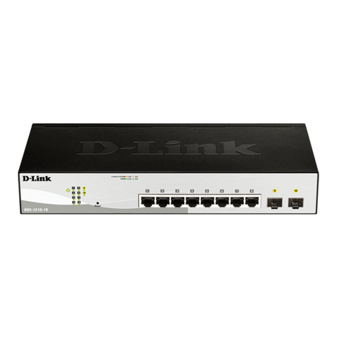
Sensit TSZ3H-24 User manual

SENSIT s.r.o.
Školní 2610, 756 61 Rožnov pod Radhoštěm, ID No. 64087484, VAT No. CZ64087484, Phone: +420 571 625 571, Fax: +420 571 625 572
Company is incorporated in the Companies Register at the Regional Court in Ostrava, Section C, File 13728, sensit@sensit.cz, www.sensit.cz
5407.1
01.17
Supersede
INSTRUCTION MANUAL
TEMPERATURE SWITCHES
TSZ3H-24
These temperature switches with display are designed for using as two-state
controller (on/off type control) for compare the temperature set-point with the
actual temperature value in range -50 to 250°C, with the possibility of
switching the electrically isolated contacts of a connected relay

Legal regulations and standards:
Electrical connection of the detector may only be carried out by a competent person with electrician qualification who
is familiarized with the "Instruction Manual" in detail.
The Instruction Manual is part of the product and it is necessary to keep it for the entire service life of the product.
The Instruction Manual must be transferred to any other owner or user of the product.
The disposal must be performed in compliance with the Directive 2008/98/EC of the European Parliament and of the
Council - on waste and the Directive 2012/19/EU of the European Parliament and of the Council –on waste electrical
and electronic equipment (WEEE), as amended
The switches are delivered in packages, which guarantee resistance to mechanical influences and that meet the
conditions with the European Parliament and Council Directive 94/62/ES on packaging and packaging waste.
The final metrological inspection –comparison with standards or working instruments –is carried out for all the
products. Continuity of the standards and working measuring instruments is ensured within the meaning of the
Section 5 of Act no.505/1990 on metrology. The manufacturer offers a possibility to supply the sensors calibrated in
SENSIT s.r.o. laboratory (according to EN ISO/IEC 17025 standard) or in an Accredited laboratory.
Application:
These temperature switches with display are designed for using as two-state controllers (on/off type control). They
compare the temperature set-point with the actual temperature value and enable switching the galvanically isolated
(electrically isolated) contacts of a connected relay. Supply voltage of the switches is 7 to 36 V DC or AC. Two
temperature sensing elements on the base of Pt (Pt 100/3850) or on the base of Ni (Ni 1000/6180) can be connected to
the switches. The display indicates the present value of the measuring temperature during measure process. Setting of
individual parameters is executed by two control buttons.
The switch can be used in 5 different modes:
the switch operates as a single controller which switches the first relay by the set temperature interval and the second
relay is switched at the exceeding set emergency temperature (only one sensing element is used)
the switch operates as a single controller which switches each relay by the set temperature interval (only one sensing
element is used)
the switch operates as a double controller, it means that each relay is controlled by the temperature of one sensing
element
the switch operates as a differential controller which switches on the base of temperature difference of two sensing
elements (analogous to mode no. 1)
the switch operates as a differential controller which switches on the base of temperature difference of two sensing
elements (analogous to mode no. 2)
The time delay of switching-off for the relay 1 within the limits 0–300 s can be set in each mode. The switches are
intended for assembly to the DIN rail. Maximum operating temperature range of the switch is -50 to 250 °c. The switches
are intended for operating in a chemically non-aggressive environment.
Recommended use and location of switches:
Operating position is arbitrary, the switches are designed for installation in the switchboard boxes on DIN rail.
Warnings and restrictions:
The switches must not be used for measuring in locations:
Where the specified technical parameters and operating conditions are not adhered
Where the converter is exposed to mechanical action or I locations with explosion hazard
With chemically aggressive environment that does not correspond the used metal materials
Where the converter is exposed to dust and humidity
It is not suitable to use the convertors for measuring in locations:
Where the supply cable might run parallel to mains cables (risk of interference signal induction and the measurement
results may be influenced), the safe distance from mains power cables when cables run parallel can be as much as
0,5 m according to the nature of interfering fields.
Failure to follow the said recommendations will negatively affect measurement accuracy, reliability and service life of the
convertor.
Product safety:
Product safety and technical parameters were evaluated according to the following standards and norms, as amended:
EN 61003-1, EN 60 529
EN 50121-3-2 –part 7, EN 50121-3-2 –part 8, EN 61000-4-2, EN 61000-4-3, EN 61000-4-4, EN 61000-4-5,
EN 61000-4-6

Declaration of conformity:
SENSIT s.r.o. provides the product with the EU Declaration of Conformity issued according to Act No. 90/2016 Coll.
and Act No. 22/1997 Coll., as subsequently amended. The product is in accordance with the following directives:
European Parliament and Council Directive 2011/65/EU of 8 June 2011 on the restriction of the use of certain
hazardous substances in electrical and electronic equipment
European Parliament and Council Directive 2014/30/EU of 26 February 2014 on the harmonisation of the laws of the
Member States relating to electromagnetic compatibility
Switches description:
The product consists of a plastic box with the terminals for connecting power supply, signal from temperature sensor end
for connecting output contacts of a relay. Inside of the box is placed the electronic mudule with a display unit for
displaying the measured temperature and other setting data. The part of the plastic box is a grip for DIN rail. The
material of the plastic box is LEXAN™ RESIN –EXL 5689.
Switches installation:
1. Place the converter to the DIN standard rail using a grip, which is a part of the plastic box
2. Connect the cable from resistance sensor Pt 100/3850 or Ni 1000/6180 and from power supply into appropriate
terminals according to wiring diagram. Connect the cable to the output relay contacts according to the wiring
diagram.
3. After installation and connection to the consequential electrical measuring device, the sensor is ready for operation.
The sensor does not require any special manipulation or maintenance.
Wiring diagram:
Description of display:
Range of the displayed temperature -50,0°C to +250,0°C
if the value is out of range the following indication is displayed
„uuu“ if the temperature is lower than -50,0°C
„nnn“ if the temperature is higher than +250,0°C
„OPn“ if any sensing element is not connected or if an input is short-circuited on power
„ShC“ if an input is short-circuited on GND
if the relay is short-circuited in emergency mode, the red LED blinks slowly
if the relay is short-circuited in operating mode, green LED or red LED is alight
TSZ3H24
Rele1
Rele2
1
-+

Control buttons and indicating LED:
LED L1, green: relay1 in operating mode: short-circuited - is alight / break - is not alight
LED L2, red: relay2 in operating mode: short-circuited - is alight / break - is not alight
relay2 in emergency mode: short-circuited - blinks slowly
break - is not alight
mode for displaying or value setting - blinks quickly
Multifunction button No.1 Menu : setting of switch values downwards and indicating of set value –long press
Multifunction button No.2 : setting of switch values upwards
Synchronous pressing of multifunction button No.1 and 2 : calling RESET
Setting of the switch:
- The setting is performed by means of the left (SW1) and the right (SW2) button. After pressing the button SW1 the red
LED blinks and thereby indicates that the display does not measure the actual temperature but some of parameters.
During the parameters editing the measurement is not perform and state of the relay is not changed.
Parameter display:
- Indicating of adjusted parameters is made by means of long pressing of the button SW1. The parameters are displayed
stepwise including their identifiers.
Setting of parameters:
- Adjustable parameters are cyclically switched over by means of holding the button SW1. The number of the
parameters is dependent on the selected function of the switch. First a parameter indicator is displayed (for example
„Fnc“, „rt1“, …) and afterwards its set value is indicated. As the first the type of function (parameter „Fnc“) is always set.
A characteristic of relay switching can be set by means of hardware circuits or by means of software. If the adjusted
temperature tLx is higher or lower then tHx - see the following characteristics.
function 01
- temperature is read out by means of one sensing element (Rt1); relay1 switches in operating mode, relay2 switches in
emergency mode.
function („Fnc“) → sensing element1 („rt1“) → temperature tL1 („tL1“) → temperature tH1 („tH1“) → alarm tALT („Alt“) →
brightness („bri“)
function 02
- temperature is read out by means of one sensing element (Rt1); relay1 and relay2 switch in operating mode
function („Fnc“) → sensing element („rt1“) → temperature tL1 („tL1“) → temperature tH1 („tH1“) → temperature tL2 („tL2“)
→ temperature tH2 („tH2“) → brightness („bri“)
short
r break
temperature
tL1/L2
tH1/H2
relay
relay1/ relay2
tL1/L2<tH1/H2
short
break
temperature
tL1/L2
tH1/H2
relay
relay1/ relay2
tL1/L2>tH1/H2
short
temperature
tL1
tH1
tALT
relay
relay1
relay 2
tL1<tH1
short
temperature
tL1
tH1
tALT
relay
relay 1
relay 2
tL1>tH1
break
break

function 03
- temperature is read out by means of two sensing elements; relay1 and relay2 are controlled by individual temperatures
independently from each other
function („Fnc“) → sensing element1 („rt1“) → temperature tL1 („tL1“) → temperature tH1 („tH1“) → sensing element2
(„rt2“) → temperature tL2 („tL2“) → temperature tH2 („tH2“) → brightness („bri“)
function 04
- temperature is read out by means of two sensing elements; relays are controlled by their temperature differences dt =
│tRt1-tRt2│; relay1 switches in operating mode, relay2 switches in emergency mode.
function („Fnc“) → sensing element1 („rt1“) → sensing element2 („rt2“) → temperature difference dtL1 („tL1“) →
temperature difference dtH1 („tH1“) → → alarm dtALT („Alt“) → brightness („bri“)
function 05
- temperature is read out by means of two sensing elements; relays are controlled by their temperature differences dt =
│tRt1-tRt2│; relay1 and relay2 switch in operating mode.
function („Fnc“) → sensing element1 („rt1“) → temperature difference dtL1 („tL1“) → temperature difference dtH1 („tH1“)
→ sensing element2 („rt2“) → → temperature difference dtL2 („tL2“) → temperature difference dtH2 („tH2“) → brightness
(„bri“)
Note: sensor Rt2 is not used in functions 01 and 02
relay1 contacted - interconnection of the terminals 1,3; relay2 contacted - interconnection of the terminals 4,6
the relay can be set as short or break for all function
The delay function
- the delay function (dL1) is used for setting time delay for break relay1 in range 0 –299s.
Setting of the sensor:
- the type of sensor is set according the next table:
Type of sensor
Setting
Pt 100/3850
Pt
Ni 1000/6180
Ni
short
break
temperature
tL1/L2
tH1/H2
relay
relay1/ relay2
tL1/L2<tH1/H2
short
break
temperature
tL1/L2
tH1/H2
relay
relay1/ relay2
tL1/L2>tH1/H2
short
break
temperature
dtL1/L2
dtH1/H2
relay
relay1/ relay2
dtL1/L2<dtH1/H2
short
break
temperature
dtL1/L2
dtH1/H2
relay
relay1/ relay2
dtL1/L2>dtH1/H2
short
break
temperature
dtL1
dtH1
dtALT
relay
relay1
relay2
dtL1<dtH1
short
break
temperature
dtL1
dtH1
dtALT
relay
relay1
relay2
dtL1>dtH1

Note:
After releasing the button SW1 while indicating required parameter the set point value can be adjusted by means of the
buttons SW1 (Down) and SW2 (Up). The buttons are provided by a two-step autorepeat, it means while pressing the
button the selected parameter is changed at the beginning slowly and after approximatelly 10 s quickly. After releasing
the button the parameter is saved in memory in a few moments and the switch is reverted in standard displaying.
Deactivation of the emergency relay (only for the functions 01 and 04):
SW1+SW2: on the display the value „rSt“ is indicated and the emergency relay is deactivated. Deactivation goes through
only in this case if temperature falls under set alarm temperature.
Attention!!!
If the power supply of the switch is broken the relay terminals 9, 10 (relay1) and 12, 14 (relay2) are interconnected.
If the power supply of the switch is broken the last state of the emergency relay is load in the processor memory
(functions 01 and 04). Change of the state of the emergency relay has no influence on the function of the operating
relay.
Technical parameters:
Operating conditions:
temperature round the converter: -30 °C to 70 °C
relative humidity of the surroundings: 10 to 80 %
atmospheric pressure: 70 to 106 kPa
Storage:
Ambient temperature 5 to 40 °C
Humidity 5 to 85%
Delivery:
Each delivery contains the following unless otherwise agreed by the customer:
Converter according to purchase order
Instruction Manual, including Guarantee Certificate
Delivery Note
Likvidace:
SENSIT s.r.o. has signed an agreement with the Company RETELA s.r.o., on the collective performance by §37h -
paragraph1, letter c) of the Act No.185 / 2001 Sb. on waste, as amended.
Complaints and repairs:
Guarantee and after-guarantee repairs of sensors are ensured by the manufacturer. The product must be delivered
including a copy of the Guarantee Certificate, duly packed and fit to shipment so as not to get damaged during
transportation.
Type of element
Pt 100/3850 or Ni 1000/6180
Temperature element wiring
Two - wire
Measuring range
-50 to 250 °C
Temperature operating range
-50 to 250 °C, step 0,1°C
Maximum error of the electronic module
± (0,2% from value + 2 dig)
Recommended power supply
230 VAC
Maximum switched voltage / current
7 to 36 VDC nebo VAC
The type of Display
4-digit LED
Character height
10 mm
Display resolution
0,1°C
Display updating
< 0,2 s
Default parameters
Fnc = 01; Rt1 = Pt; tL1 = 10,0; tH1 = 15,0; dL1= 00;
Rt2 = Pt; tL2 = 20,0; tH2 = 25,0; Alt = 30,0; bri = 0
Recommended wire
cross section: 0.35 to 1,5 mm²
Box / terminals IP code
IP 20
Dimension / material of the box
86 x 69 x 49 mm / ABS
Weight
0,22 kg

GUARANTEE CERTIFICATE
The product is covered by guarantee for 24 months from the date of purchase.
In this period, the manufacturer will remove all material or manufacturing defects arisen demonstrably during the
applicable warranty period. The manufacturer is liable for the technical and operational parameters of the product given
in the user manual. Any identified defects will be claimed by the buyer without undue delay after their identification or, as
appropriate, after the buyer was able to identify them during his routine care. A completed Warranty Certificate with a
brief description of the defect plus the product must be submitted with the claim.
Warranty does not cover a product:
That was damaged during transport and inappropriate storage, improper commissioning and/or that has been used for
a purpose other than specified
That has been used in an improper manner, inconsistent with the user manual and/or generally applicable technical
standards or safety regulations
That is worn or damaged as a result of normal use of the product, without loss of its operational characteristics and
guaranteed technical parameters
Into which unskilled intervention, unauthorised structural or other changes (reprogramming, resetting of set
parameters, etc.) have been made
That is mechanically damaged, e.g. by fall, being hit by a hard object, cleaning with unsuitable agents, power cord
tearing/breaking, breaking or other damage of individual product parts
That has been exposed to adverse external influence, e.g. object intrusion, wrong supply voltage, influence of
chemical processes, electrical surge (obviously burnt components or printed circuits), dusty, dirty, aggressive or
otherwise unsuitable environment, except normal variation
That has been damaged by an incidental or natural disaster or as a result of natural or external phenomena, such as
storm, fire, water, excessive heat
That is claimed without the Warranty Certificate or nameplate.
Rights and obligations regarding the rights arising from defective performance will be governed by the applicable
legislations and the applicable Business Terms and Conditions of SENSIT s.r.o. and this Warranty Certificate.
Date of sale confirmation:
Serial number:
Table of contents


