manuals.online logo
Brands
  1. Home
  2. •
  3. Brands
  4. •
  5. Autonics
  6. •
  7. Switch
  8. •
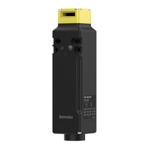
  9. Autonics SFDL2 Series User manual

Autonics SFDL2 Series User manual

-|Transparent Guide|-
TCD210223AB
Safety Slim Type
Door Lock Switch
SFDL2 Series
PRODUCT MANUAL
For your safety, read and follow the considerations written in the instruction
manual, other manuals and Autonics website.
󹃑

󹮭󹮭󹮭󹮶󹮵
Main Features
󹮭 󹮭󹮭󹮭󹮭󹮭󹮭󹮭󹮭󹮭󹮵󹮭
󹮭 󹮭󹮭󹮭󹮭󹮭󹮭󹮭󹮭󹮭󹮭󹮭
󹮷󹮭󹮭󹮭󹮭󹮭󹮭󹮭󹮭󹮭󹮱󹮶󹮲
󹮭 󹮭󹮭󹮭󹮱󹮭󹮭󹮴󹮲
󹮷󹮭󹮭󹮵󹮵󹮭󹮶󹮵󹮵󹮭󹮭󹮵󹮵󹮭󹮶󹮵󹮵
󹮭󹮵󹮵󹮭󹮭󹮵󹮵󹮭󹮶󹮵󹮵
󹮭󹮵󹮵󹮭󹮶󹮵󹮵󹮭󹮭󹮵󹮵󹮭
󹮭󹮵󹮵󹮭󹮭󹮵󹮵󹮭
󹮭 󹮭󹮭󹮭󹮱󹮭󹮲󹮭󹮭󹮭󹮭󹮭󹮭
󹮷󹮭󹮭󹮱󹮲󹮭󹮭󹮭󹮭󹮭󹮭󹮳󹮭󹮭󹮭
󹮭 󹮭󹮴󹮭
󹮷󹮭󹮭󹮴󹮭󹮳󹮭󹮭󹮴󹮭󹮭
󹮭 󹃐󹮭󹮭󹮭󹮭󹮭󹮭󹮭󹮭
󹮷󹮭󹮭󹮶󹮭󹮭󹮭
󹮭 󹮭󹮭󹮭󹮭󹮭󹮭󹮭
01. Use the unit within the rated speci󹃒cations.
󹃑
02. Since solenoid has polarity, wire cables and supply voltage ensuring correct polarity. Do not
supply voltage above the rated voltage speci󹃒cation.
󹃑
03. Be sure to install the cover after wiring work, and do not apply power with the cover open.

04. Use a dry cloth to clean the unit, and do not use water or organic solvent.
󹃑
05. Keep the door switch away from debris and tighten the screw securely when replacing the
head.

06. Keep the product away from metal chip, dust, and wire residue which might 󹃓ow into the
unit.
󹃑
07. Do not use metallic cable gland.


08. Do not use the switch as a guard door stopper. Install separate mechanical stopper.

09. Carefully manage the spare operation key in order to prevent use of the key without
permission.


10. Use only Autonics operation key.

Safety Considerations
• 
• 
᜸ Warning 
01. Fail-safe device must be installed when using the unit with machinery that may cause
serious injury or substantial economic loss. (e.g. nuclear power control, medical equipment,
ships, vehicles, railways, aircraft, combustion apparatus, safety equipment, crime/disaster
prevention devices, etc.)
󹃑
02. System manager means followings;
- a personnel who is fully aware of installation, setting, operation, and maintenance of the
product
- a personnel who well observes standard/regulation/statute on the product by type of
machine the product installed in and nation/region the product used in
Machine user means a personnel who is appropriately trained about using machine by the
system manager, so that machine user can operate the machine correctly.
System manager has duty to train the machine user about operation of the product.
Machine user has to report directly to the system manager when unusual status has been
found while system is operating.
󹃑
03. The product has to be installed, set, and combined with machine control system by the
quali󹃒ed system manager.


04. Before using the product, check that function of the product operates as intended while
machine is turned o󹃑 after installation.


05. Do not use the unit in the place where 󹃓ammable/explosive/corrosive gas, high humidity,
direct sunlight, radiant heat, vibration, impact, salinity, moisture, or steam, or dust may be
present.
󹃑
06. Do not disassemble or modify the unit.
󹃑
07. Do not defeat, tamper, modify, or bypass the switch and enter the door.

08. Be cautious about the installing place of the operation key in order to protect worker from
hitting the operation key when the door is opened.

09. Do not use a head of other product.
󹃑
10. Install separate safety device to 󹃒x door closed, or door can be opened because of vibration
or weight of the door.

11. Check the installed status of the switch, operating status of the switch, and signs of damage,
modi󹃒cation, tampering of the switch at the following situation and on a weekly basis.
- when operating the safety system at 󹃒rst
- when replacing component of the system
- when the system has not been operated for a long time


12. Solenoid Lock/Mechanical Release type switch is locked with power connected and is
unlocked without power. Be cautious that the switch can be unlocked before complete stop
of the machine when blackout occurs.

13. Check ‘Connections’ before wiring.
󹃑
᜸ Caution 
-|Transparent Guide|-
Product Components
•  •  • Special type release key

11. Install the operation key tightly within the range written in ‘Installation’ with welding, rivet, or
special bolt in order not to be easily released from the switch.

12. When it comes to the Solenoid Lock/Mechanical Release model, make it to be locked by
supplying power after the door is closed.

13. When changing the direction of the head, make sure that the cam inside the head does not
rotate.

Cautions during Use
• 
• 

• 
󹃑




Sold Separately
• 
Contact block




 


 
 
Electrical
life cycle 
 100 A
Solenoid


 

 Class E
Indicator LED


 
Model SFDL2-□□□-□□ -□
SFDL2-□□□-□□K-□ SFDL2-□□□-□□ B-□
SFDL2-□□□-□□KB-□
Directing opening force 
Directing opening distance 
Locking pullout strength 
Operating speed 
Operating frequency 
Mechanical life cycle 
Indicator 
 -
Vibration (malfunction)-

Shock 2
Shock (malfunction)2
Ambient temperature 
Ambient humidity 

Protection structure 
Material 
Approval 󹮭
Accessory □□
Unit weight (packaged) 


Speci󹃒cations
Ordering Information

󹃑
SFDL2 -❶ ❷ 6❸-❹❺❻❼ -❽
❶ Head material


❺ Connection outlet speci󹃒cation


❷ Lock/Release method


❻ Release key type


❸ Contact composition




❼ Rear release button


❹Installation direction


❽ Release key position


Connections
• 
󹃑


11 
21
 

 
• 

󹃑







Manufacturer Model
JST 󹃒

Installation
• 

• 

R1

R2
Operation
key
Minimum radius
R1 R2
 300 mm 300 mm
 300 mm 300 mm
 300 mm 300 mm
 300 mm 300 mm
  300 mm
  300 mm
• 


• 
Screw Tightening torque

m

m

m
 

m

m
 m
• 

 
• 󹃑

Thread
spec MFR Model Cable Ø
 CP

 
 
M20 LAPP 
 
• 

󹃐
• 󹮭󹮭󹮭󹮭󹮵
• 


• 
Model
Contact
(lock monitor+
door monitor)
Connection diagram
Contact operation
Door monitor Lock monitor





complete


key





1 1
2 1
1 2
2 2



 


3 3






 
1 1
2 1
1 2
2 2



 


3 3






 
1 1
2 1
1 2
2 2
3 2


 


3 1



31-32


 
1 1
2 1
1 2
2 2
3 2


 


3 1



31-32

Contact Composition and Operation

( 

-|
Transparent Guide|-
Manual Unlock
•
■Release key
Release key Normal Manual
unlock
Cross type
Special type
•
•
•˚
•
■Rear release button
•
•
•
Dimensions
•
■Frontinstallation
•
30
2
2to
■Rear installation
0
20
12
■Panel cut-out
••
3
(rear rele tt
20
32
20
32
Sold Separately: Operation Key
•
■SFD-KH ■SFD-KL
10
20
30
22
2
2
R3
10
10
20
30
■SFD-KHR ■SFD-KLR
22
10
20
30
2
R3
10
10
20
30
2
■SFD-KLF, SFD-KLF2
Model Material
2
30
20

Other Autonics Switch manuals

Autonics PFI Series User manual

Autonics

Autonics PFI Series User manual

Autonics SFEN Series User manual

Autonics

Autonics SFEN Series User manual

Autonics SPB Series User manual

Autonics

Autonics SPB Series User manual

Autonics BEN Series User manual

Autonics

Autonics BEN Series User manual

Autonics SF2KR Series User manual

Autonics

Autonics SF2KR Series User manual

Autonics AS Series User manual

Autonics

Autonics AS Series User manual

Autonics ARIO-C-MT User manual

Autonics

Autonics ARIO-C-MT User manual

Autonics SFD Series User manual

Autonics

Autonics SFD Series User manual

Autonics SFDL Series User manual

Autonics

Autonics SFDL Series User manual

Autonics PR Series User manual

Autonics

Autonics PR Series User manual

Popular Switch manuals by other brands

Compaq HB1004 user guide

Compaq

Compaq HB1004 user guide

Extron electronics System 8/10 Plus user manual

Extron electronics

Extron electronics System 8/10 Plus user manual

steute RF RC M30 SW868 RF HS M30 SW868 Mounting and wiring instructions

steute

steute RF RC M30 SW868 RF HS M30 SW868 Mounting and wiring instructions

Bogen CA19 install guide

Bogen

Bogen CA19 install guide

Lindy 42321 user manual

Lindy

Lindy 42321 user manual

Weidmüller ValueLine IE-SW-VL08-GT Series Hardware installation guide

Weidmüller

Weidmüller ValueLine IE-SW-VL08-GT Series Hardware installation guide

StarTech.com SV231HU34K6 quick start guide

StarTech.com

StarTech.com SV231HU34K6 quick start guide

Pepperl+Fuchs SIL LVL-M4 manual

Pepperl+Fuchs

Pepperl+Fuchs SIL LVL-M4 manual

StarTech.com SV431HDU3A2 quick start guide

StarTech.com

StarTech.com SV431HDU3A2 quick start guide

Kobold KAL-8115FL User instructions

Kobold

Kobold KAL-8115FL User instructions

D-Link DIR 601 - Dlink Wireless N 150 Home Router product manual

D-Link

D-Link DIR 601 - Dlink Wireless N 150 Home Router product manual

Allied Telesis AT-8316F/MT Quick install guide

Allied Telesis

Allied Telesis AT-8316F/MT Quick install guide

Hootoo HT-UH010 user manual

Hootoo

Hootoo HT-UH010 user manual

Cisco Nexus 9000 Series Quick start configuration guide

Cisco

Cisco Nexus 9000 Series Quick start configuration guide

Ubiquiti UniFi US-8-60W quick start guide

Ubiquiti

Ubiquiti UniFi US-8-60W quick start guide

FSR SN-4100 Operation manual

FSR

FSR SN-4100 Operation manual

Linear Technology DC252 Demo Manual

Linear Technology

Linear Technology DC252 Demo Manual

Ross MC1-MK operating instructions

Ross

Ross MC1-MK operating instructions

manuals.online logo
manuals.online logoBrands
  • About & Mission
  • Contact us
  • Privacy Policy
  • Terms and Conditions

Copyright 2025 Manuals.Online. All Rights Reserved.