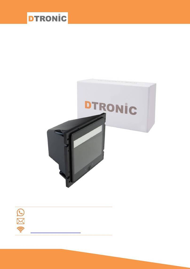
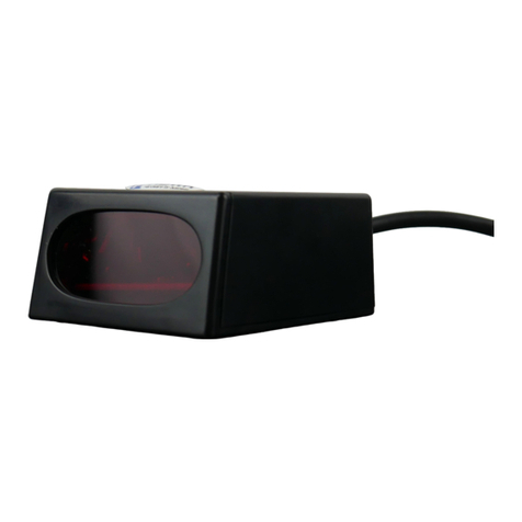
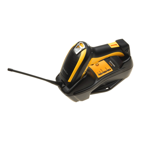
Senso KSK2 User manual

DEVELOPEMENT
MANUAL
CMOS BARCODE SCANNER
Version: v2.0.10
KSK2

CONTENT
1Brief description.....................................................................................................1
2System Setting .......................................................................................................1
2.1 Setting code switch.................................................................................1
2.2 Switch for setting code data output......................................................1
2.3 Parameters setting....................................................................................1
2.4 Device information ..................................................................................2
2.4.1 Firmware version..............................................................................2
2.4.2 Unique identification code of device.............................................2
2.5 Custom product model............................................................................2
2.5.1 Set custom product model number ................................................2
2.5.2 Read custom product model number .............................................3
2.6 Restart.......................................................................................................3
3Communication setting..........................................................................................4
3.1 Interface settings......................................................................................4
3.1.1 UARTserial output ............................................................................4
3.1.2 UART serial port work settings .....................................................4
3.1.3 UART serial port baud rate setting ...............................................5
3.1.4 USB HID keyboard output..............................................................5
3.1.5 USB HID keyboard output Chinese settings ................................6
3.1.6 USB HID keyboard output interval time ......................................6
3.1.7 USB HID virtual keyboard numeric keyboard selection.............7
3.1.8 USB HID keyboard layout..............................................................7
3.1.9 USB virtual serial port output........................................................8
3.1.10 USB HID POS output.....................................................................9
3.2 Host command response mode ..............................................................9
3.3 Heartbeat query......................................................................................10
3.3.1 1 Heartbeat mode 1.........................................................................10
3.3.2 Heartbeat mode 2.....................................................................................10
4 Reading parameter settings....................................................................................11
4.1 Reading mode ........................................................................................11
4.1.1 Auto-sensing mode .........................................................................11
4.1.2 Continuous Mode............................................................................11
4.1.3 Manual mode(button/key mode)....................................................11
4.1.4 Command trigger mode .................................................................12
4.2 Automatic sensing sensitivity...............................................................12
4.3 Auto-sensing restart delay setting........................................................13
4.4 Auto-sensing button mode(for engine)...........................................13
4.5 Time of single reading .........................................................................14
4.6 The choice after reading is completed(In auto-sensing mode)..............15
4.7 Manual query of motion detection status.................................................15

4.8 Motion detection status is automatically sent..........................................16
4.9 Interval of barcode reading........................................................................16
5 Fill-Light and Aiming-Light..................................................................................18
5.1 Fill-Light.................................................................................................18
5.1.1 Mode of fill-light............................................................................18
5.1.2 Control method of fill-light...........................................................18
5.1.3 Set fill-light in level-mode............................................................19
5.1.4 Lighting brightness setting.............................................................19
5.1.5 Automatically turn on the fill light in dark environment.........20
5.1.6 Automatic fill light threshold..........................................................20
5.1.7 Time interval of auto fill-light on .................................................20
5.2 Aiming-Light ..........................................................................................21
5.2.1 Aiming-Light mode ........................................................................21
5.2.2 Aiming light flashes.......................................................................22
6 Prompt during output.............................................................................................23
6.1 Power-on prompt ...................................................................................23
6.2 Buzzer prompt when reading...............................................................23
6.3 Buzzer prompt when setting ................................................................23
6.4 LED Indicator light...............................................................................24
6.4.1 LED Indicator light ON/OFF........................................................24
6.4.2 Set the working level of the reading result indicator...............24
6.5 Fill-Light control signal output............................................................24
6.6 Power-on command prompt..................................................................25
6.7 Buzzer sound duration ..........................................................................25
6.8 Buzzer signal output mode...................................................................25
6.9 Buzzer frequency...................................................................................26
6.10 Buzzer loudness adjustment..................................................................26
6.11 Buzzer working level............................................................................27
7 Data editing.............................................................................................................28
7.1 Remove original data settings..............................................................28
7.1.1 Example 1 Remove the first 20 bytes of user data..................28
7.1.2 Cancel remove the previous data.................................................28
7.1.3 Example 2 Remove the 20 bytes of data after the data..........29
7.1.4 Cancel to remove the data of end...............................................29
7.2 Only output data at both ends(remove middle data)........................29
7.2.1 Example 1 Only output the first 20 bytes of data .....................30
7.2.2 Cancel only output the first end data ...........................................30
7.2.3 Example 2 Only output the last 20 bytes of data ......................30
7.2.4 Cancel only output backend data...................................................31
7.3 Add prefix..............................................................................................31
7.3.1 Add prefix example1 example2......................................................31
7.3.2 Clear prefix .......................................................................................32
7.4 Add suffix ..............................................................................................32
7.4.1 Add suffix example1 example2 ......................................................32

7.4.2 Clear suffix........................................................................................33
7.5 Data filtering rule settings....................................................................33
7.5.1 example 1 Filter a0 in the data.....................................................33
7.5.2 Clear filter rules ...............................................................................34
7.6 CRC Check ............................................................................................34
7.7 Terminator...............................................................................................35
7.8 Barcode type character output .............................................................35
7.9 Case output settings ..............................................................................36
7.10 Prohibit URL output..............................................................................36
8 Barcode reading configuration...............................................................................37
8.1 All barcode configurations....................................................................37
8.2 Single barcode configuration................................................................37
8.2.1 CODE 128.......................................................................................38
8.2.2 GS1_128 ..........................................................................................39
8.2.3 CODE39...........................................................................................39
8.2.4 Interleaved 2 of 5..........................................................................41
8.2.5 Straight 2 of 5 industrial ..............................................................42
8.2.6 Straight 2 of 5 IATA.....................................................................43
8.2.7 Matrix 2 of 5 .................................................................................43
8.2.8 Grid Matrix .....................................................................................44
8.2.9 CODE 93.........................................................................................45
8.2.10 CODE 11.........................................................................................45
8.2.11 CODABAR......................................................................................46
8.2.12 TELEPEN........................................................................................47
8.2.13 MSI ..................................................................................................48
8.2.14 GS1 DataBar(RSS) .........................................................................48
8.2.15 PDF417............................................................................................49
8.2.16 MICRO PDF...................................................................................50
8.2.17 Aztec Code......................................................................................50
8.2.18 MaxiCode.........................................................................................51
8.2.19 MICRO QR.....................................................................................51
8.2.20 Han Xin code .................................................................................51
8.2.21 China Post (Hong Kong 2 of 5) .................................................52
8.2.22 Data Matrix.....................................................................................52
8.2.23 NEC 2 of 5....................................................................................53
8.2.24 UPC-A..............................................................................................54
8.2.25 UPC-E0 & UPC-E1 .......................................................................55
8.2.26 EAN/JAN-13....................................................................................57
8.2.27 EAN/JAN-8......................................................................................59
Appendix 1 Barcode Type Output Character List..................................................61
Appendix 2 Digital Code ..........................................................................................61
Appendix 3 CODE39 FULL ASCII Correspondence Table..................................63
Appendix 4 Test Barcode..........................................................................................64

1
1Brief description
This manual mainly provides various function setting commands for barcod
e reading equipment. By familiarizing with the introduction of various function
commands in this manual, users can change the function parameters of the ba
rcode reading device by scanning the setting code or sending setting commands
through the interface. The product has provided parameter configuration suitab
le for most common application functions at the factory. In most cases, the us
er can put it into use without adjustment. The factory default is UART serial
port output, and the default baud rate is 9600.
REMARK:
(1) All setting parameters with * are system default parameters;
(2) The CRC included in the commands in this document uses CRC16_XMOD
EM, polynomial x16+x12+x5+1 (0x1021), the data is reversed to MSB First, a
nd the data format is a string format configuration. For example, a command i
s: $xxxxxx-yyyy, the 4 digits of yyyyare the check code, and $xxxxxx-the 8 d
igits are the content for calculating the checksum.

1
2System Setting
2.1Setting code switch
This function is whether the user can set up the device by scanning the settin
g code. After the setting code is turned off, the parameter configuration cannot be
performed by scanning the setting code. The setting code is regarded as a normal
barcode; after the setting code is turned on, the parameter configuration can be p
erformed by scanning the setting code. The default is that the switch is on
Command for off setting code switch:$010000-525C
Command for on setting code switch:$010001-616D
Note: These two commands can only be set by sending commands throug
h UART and other interfaces
2.2Switch for setting code data output
This function is whether the user outputs the scanned setting code content thr
ough the UART interface.
2.3Parameters setting
Rest to factory default
Restore all parameters to the factory default, the device will automatically rest
art after this operation.
$010100-24E8
(*No output)
$010101-17D9
(Output)
$010200-BF34
(Reset)

2
2.4Device information
2.4.1 Firmware version
2.4.2 Unique identification code of device
After reading successfully, the device will return a string of 12 bytes to the h
ost. Can be used to identify products.
2.5Custom product model
2.5.1 Set custom product model number
Under this function, the user can name the product model number by himself, an
d then it can be read by the read command. The steps to set a custom product model
are as follows:
(1) Set the custom product model number by scan following setting codes:
$010300-C980
(Output firmware version)
$0103A0-26B8
Read the unique code of the device (12 characters)
$010204-73F0 Enter the setting state of custom product model name

3
(2)Make a non-setting QR code of a customized product model number and sca
n the code. The buzzer sounds three times to indicate the setting is successful, an
d the buzzer sounds once to indicate the setting failed. as follows:
Custom product model number test code, scan the following code after setting
in step (1), the custom product model will be set to CUSTOM PRODUCT MOD
EL TEST, scan 2.5.2 to read the command code of the custom product model or
send a command It can be read out.
Notice:
a. The total characters of the customized product model number cannot excee
d 100 bytes, otherwise the setting will fail;
b. After the setting fails, you need to restart the setting from step (1);
c. After the setting is successful, if you want to modify the setting model, dir
ectly restart the setting from step (1), and the original setting model will be cleare
d; d. After the setting is successful, restoring the factory settings will also retain
the set model number.
2.5.2 Read custom product model number
Read the customized product model number set by the user
2.6 Restart
The device will restart immediately after scanning the setting code or sending
the setting command.
$010205-40C1 (read customized product model number)
$010500-EE19 (Restart)

4
3Communication setting
3.1Interface settings
The factory default is UART interface output. If you need other interface
output, scan the enable code of the corresponding interface to switch, the settin
g will not take effect immediately, you need to manually restart the device to
take effect, and the set interface will not be restored after scanning and restori
ng the factory settings. Keep the original settings unchanged.
3.1.1 UARTserial output
If the data output interface is switched to UART serial output, it will not
take effect immediately, and it needs to be manually restarted to take effect.
The default output configuration of the serial port is: baud rate-9600bps, s
top bit-1 bit, data bit-8 bits, parity bit-none, no flow control. The baud rate ca
n be changed according to the setting in section 3.1.3.
3.1.2 UART serial port work settings
By default, the UART serial port keeps sending no matter what interface o
utput mode it is in. The receiving will be turned off in the USB virtual serial
port output mode, and it will be turned on in other modes. It can be set to
only use the serial port to transmit data in the UART serial port output mode.
(Note: The default parameter of v4.x.39, v6.0.9 and higher version is "only
work in UART serial output mode", the default parameter before v4.x.39, v6.
0.9 is "no matter what interface Keep working in output mode".)
$020003-C9EF
UART serial output

5
3.1.3 UART serial port baud rate setting
The baud rate of the serial port is adjustable, and the default bit is 9600, whi
ch will take effect immediately after setting.
3.1.4 USB HID keyboard output
$020503-75AA(Baud rate2400)
$020504-EC3D(Baud rate4800)
$020505-DF0C (* Baud rate9600)
$020506-8A5F(Baud rate19200)
$020507-B96E (Baud rate38400)
$020508-A950(Baud rate57600)
$020509-9A61(Baud rate115200)
$020E01-51BD
Keep working regardless of interface out
put mode
$020E00-628C
*Only work in UART serial port output
mode

6
The data output switch bit USB HID keyboard interface output will not ta
ke effect immediately, and it needs to be manually restarted to take effect.
3.1.5 USB HID keyboard output Chinese settings
USB HID keyboard output Chinese is currently only applicable to window
s system, currently does not support Chinese output on Android and Linux dev
ices. Chinese output is turned off by default.
3.1.6 USB HID keyboard output interval time
The USB HID keyboard is a character-by-character transmission. Through
this setting, the character output speed of the embedded scanner can be change
d to meet the requirements of the host. The default is 10ms interval.
$020000-9CBC (USB HID keyboard)
$020A00-A87D
*USB HID keyboard Chinese output-off
$020A02-CE1F
USB HID keyboard Chinese output-on
$020700-CD91 No interval
$020701-FEA0Interval 1MS

7
3.1.7 USB HID virtual keyboard numeric keyboard selection
3.1.8 USB HID keyboard layout
The USB HID keyboard defaults to the USA keyboard output.
$020703-98C2Interval3MS
$020705-3264 Interval5MS
$02070A-F6F9 *Interval10MS
$020714-3665 Interval20MS
$02071E-0D0D Interval30MS
$020732-F2A3 Interval50MS
$020900-6FCB * Alphabet
$020901-5CFANumeric

8
3.1.9 USB virtual serial port output
The data output is switched to the USB virtual serial port output, it will
not take effect immediately, and it needs to be manually restarted to take effec
t. In the window system, you need to install the USB virtual serial port driv
er (win10 system may automatically install it), and then use the serial port deb
ugging assistant software to open the port for debugging or development. In th
e Linux system, a ttyACM node will be added.
$020C00-4515
*USA
$020C01-7624
Belgium
$020C02-2377
Finland
$020C03-1046
France
$020C04-89D1
Germany
$020C05-BAE0
Sweden
$020C06-EFB3
U.K
$020C07-DC82
Norway
$020C08-CCBC
Spain
$020C09-FF8D
Portugal
$020C0A-7E7D
TurkeyQ
$020C0B-2B2E
Japan
$020C0C-181F
Czech Republic
$020C0D-8188
TurkeyF

9
3.1.10 USB HID POS output
In USB HID POS mode, PID is 0xA4AF, VID is 0x0525, packet size is 3
2 bytes, input is 32 bytes, output is 32 bytes, there will be a header and a he
ader before and after the module sends data.
The content of the header is: the number of bytes of the QR code content
+ the length of the check;
The content of the package is to send 32 bytes of data each time, and a
checksum is added at the end of the content. The checksum is the sum of all
the data in the content package;
The end of the packet is a packet containing only one byte of 0X0D.
(Note: Only FW v4 series version, and v4.x.39 and later versions support t
his function.)
3.2Host command response mode
When using the interface to send a setting command, it returns setting stat
usof response mode of. The default is no answer.
$020001-AF8D USB virtual serial port
$020004-5078
USB HID POS

10
No response: After sending the setting command, there is no response con
tent to return whether the setting succeeds or fails.
Response mode 1: The response is fixed content. The response to the suc
cessful execution of the command is: $000100-6148; the response to the failure
of the command execution is: $0001FF-A91F.
Response mode 2: The first 5 characters of the response are the same as
the first 5 characters of the command sent to the device; for the 6th to 7th ch
aracters, the command execution is successful: "00"; the command execution fa
ilure is: "FF"; the 8this a fixed character "-"; the 8th to 12th characters are C
RC16 checking.
Note: (1). There is no response to read commands (such as reading device
information), and the read content will be directly responded;
(2). When sending "enter online upgrade status", it will only reply that th
e command is executed successfully, which only means that the command has
been received.
3.3Heartbeat query
3.3.1 1 Heartbeat mode 1
The host can check whether the code scanning module has a heartbeat res
ponse by sending a heartbeat query command, so as to determine whether the
code scanning module is working normally.
Heartbeat query: $01036F-D9DF
Heartbeat response: $010370-4C10
3.3.2 Heartbeat mode 2
power upThe following phenomena will occur after enabling heartbeat mode 2:
1. Heartbeat will send 0x82 0x83 every 10 seconds; 2. Power up will be sent after power
-on and restart
$020B00-33A1
(* No response)
$020B01-0090
(Response mode1)
$020B02-55C3
(Response mode2)
$383700-7DC3
*heartbeat mode 2-off
$383701-4EF2
heartbeat mode 2-on

11
4 Reading parameter settings
4.1Reading mode
In order to be suitable for different scenarios, the scan code module has a
variety of reading modes, and the default is the auto sensing reading mode, T
he settings are effective immediately.
4.1.1 Auto-sensing mode
In auto-sensing mode, when a barcode enters the field of view of the dev
ice, the device will start to read it once. When the reading is successful or th
e reading exceeds the "single reading time", the reading will stop.
4.1.2 Continuous Mode
In the continuous reading mode, the device reading will continue to be tur
ned on and will not be affected by the "single reading time".
4.1.3 Manual mode(button/key mode)
In manual mode, the key will be used to control the code reading. There
are 3 control methods. In order to prevent the setting code from being scanned
by mistake and the code cannot be scanned (in the case of no button connect
ion), it is recommended to use the interface to send the setting command to s
et to this mode, so as to ensure that the setting can be set through the setting
command.
$100004-6359(*Auto-sensing mode)
$100003-FACE(Continuous mode)

12
(1)Key once trigger mode: Press the key once to start the reading. When t
he reading is successful or exceeds the "single reading time", the device stops
reading;
Command:$100000-AF9D
(2)Key hold mode: In this mode,the reading is started when the button is p
ressed, and the reading is stopped when the button is released. When the readi
ng is successful or exceeds the "single reading time",the device stops reading;
Command:$100001-9CAC
(3)Key switch continuous mode: In this mode, the key acts as a switch. W
hen it is pressed, it starts continuous reading, and when it is pressed again, it
stops reading. The opening period is not affected by the "single reading time".
Command:$100002-C9FF
4.1.4 Command trigger mode
The command trigger mode should be applicable in the key-press once tri
gger mode, the key hold mode or the auto-sensing mode. The command trigge
r in the command trigger mode is read as follows:
Command trigger 1:The reading is triggered after sending the command. Wh
en the reading is successful or exceeds the "single reading time" or when the
"command triggered stop" is received, the device stops reading;
Command:$108000-ADB0
Command trigger 2:After sending the command, the continuous reading is tri
ggered, and the device will stop reading only after sending the "command of t
rigger stop";;
command:$108001-9E81
command trigger stop:It is used to stop the reading triggered by "Command
Trigger 1" and "Command Trigger 2".
command:$108003-F8E3
4.2Automatic sensing sensitivity
This setting is only valid when the "Reading Mode" is "Auto-sensing"; the
higher the sensitivity, the easier it is to trigger the device to enter the readin
g state, the lower the sensitivity, the less likely it is to trigger the device to e
nter the reading state. The sensitivity needs to be set according to different sce
narios , Under normal circumstances, the default settings can be used. The def
ault is the highest sensitivity.

13
4.3Auto-sensing restart delay setting
This setting is only valid when the "Reading Mode" is "Auto-sensing"; it
is used to set the delay time for the next automatic sensing start after the barc
ode is read; it is not recommended to set the delay too short, otherwise it will
cause multiple readings by one scan. The default is 0.5s.。
4.4Auto-sensing button mode(for engine)
$100100-D929
*Highest sensitivity
$100101-EA18
High sensitivity
$100102-BF4B
Middle sensitivity
$100103-8C7A
Low sensitivity
$100104-15ED
Lowest sensitivity
$101304-52D4(0.3S)
$101306-34B6 (*0.5S)
$101308-17B9 (0.7S)
$10130C-C31A (1S)

14
You can choose the mode of auto-sensing and pressing the key to trigger
the reading.
One-time reading mode: press the button once to forcefully trigger an au
tomatic induction reading per unit time
Key hold mode: After pressing once or twice in a row, the module will
enter manual mode. In manual mode, the module will not automatically sense t
o trigger the reading. Press the button to trigger the reading, and release the b
utton to stop reading immediately. When the module stops reading and is idle
for 5 seconds, the module will re-enter the auto-sensing mode.
4.5Time of single reading
This setting is only valid when the "reading mode" is "one-time trigger",
"key hold", and "auto-sensing"; when the reading time exceeds the "single read
ing time", the device will stop reading. The default value is 6 seconds.
$100200-42F5
(Infinite time)
$100203-17A6
(3S)
$100206-E853
(*6S)
$100209-F86D
(9S)
$10020F-E00A
(15S)
$101500-B989(*one time reading)
$101501-8AB8 (Key hold mode)

15
4.6 The choice after reading is completed(In auto-sensing mode)
In auto-sensing mode, after finishing a reading, the module has three states tha
t can be set:
-. Keep reading state
-. Exit the reading state immediately
-. Auto-sensing end mode 3: After scanning the code successfully, the fill light
will flash once, and then continue to maintain the trigger state.
4.7 Manual query of motion detection status
query command:$380000-C23C
No motion-return:$380010-F50C
Have motion-return:$380011-C63D
$101400-CF3D
* Exit the reading state
$101401-FC0C
Keep reading state
$101402-A95F
end mode 3
$380000-C23C
Table of contents

