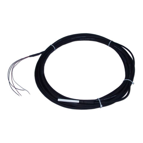
Sensonix PE-8E User manual

Instruction Manual
PE-8E
PH/ORP Meter for Industrial Use
CO., LTD.Sensonix Japan
EM07012000

Contents
11. Preface ・・・・・・・・・・・・・・・・・・・・・・・・・・・・・・・・
.22. Installation ・・・・・・・・・・・・・・・・・・・・・・・・・・・ ・・・
2
2.1 Installation sites ・・・・・・・・・・・・・・・・・・・・・・・・・・・
2
2.2 Installation way ・・・・・・・・・・・・・・・・・・・・・・・・・・・
3
2.3 Setting internal Switches ・・・・・・・・・・・・・・・・・・・・・・・
2.3.1 Definition of DIG Switch 3・・・・・・・・・・・・・・・・・・・・・
2.3.2 Definition of DIP Switch 3・・・・・・・・・・・・・・・・・・・・・
2.3.3 Confirmation of the setting contents 6・・・・・・・・・・・・・・・・・
7
3. Wiring ・・・・・・・・・・・・・・・・・・・・・・・・・・・・・・・・
7
3.1 Wiring of alarm contact output ・・・・・・・・・・・・・・・・・・・・
8
3.2 Wiring of the electrode ・・・・・・・・・・・・・・・・・・・・・
9
3.3 Wiring of transmission output cable ・・・・・・・・・・・・・・・・・
10
4. Explanation of each parts ・・・・・・・・・・・・・・・・・・・・
10
4.1 Operation keys ・・・・・・・・・・・・・・・・・・・・・・・・・・
11
4.2 Operation lamps ・・・・・・・・・・・・・・・・・・・・・・・・・
11
5. Operation ・・・・・・・・・・・・・・・・・・・・・・・・・・・・・
11
5.1 Operation Pocedures ・・・・・・・・・・・・・・・・・・・・・・・・
11
5.2 Calibration For pH meter use()・・・・・・・・・・・・・・・・・・
5.2.1 Automatic calibration procedure 12・・・・・・・・・・・・・・・・・・
5.2.2 Function of manual calibration 14・・・・・・・・・・・・・・・・・・
5.2.3 Manual calibration procedure 15・・・・・・・・・・・・・・・・・・
17
5.3 Calibration For ORP meter use()・・・・・・・・・・・・・・・・・・
5.3.1 Sensitivity confirmation by an ORP standard substance 17・・・・・・・・・
18
5.4 Parameter Display ・・・・・・・・・・・・・・・・・・・・・・・・
19
5.5 Renewal of the set value ・・・・・・・・・・・・・・・・・・・・・
・・・・・・・・・・・・・・・・・・・・・・ ・・・・
6. Error codes
20
20
6.1 Error codes of PH/ORP meter ・・・・・・・・・・・・・・・・・・・・
21
6.2 Countermeasures to error codes ・・・・・・・・・・・・・・・・・・・・
237. Spare parts Optional()・・・・・・・・・・・・・・・・・・・
248. Specifications ・・・・・・・・・・・・・・・・・・・・・・・・・・

-1-
1.Preface
Thank you very much for purchasing pH / ORP meter PE-8E for industrial use.
This manual is for PE-8E, which is dual use type of pH / ORP .
You are requested to read this manual carefully to study various functions and operations.
Moreover, this manual is very useful to your obscure points at operations and re-set of functions.
Therefore, please give care to keeping this.
This manual was published by Sensonix Japan Co.,LTD.
Copyright 1999 02.08
PrintedinJapan
All rights reserved. No part of the contents of this
manual may be reproduced or transmitted in any form
by any means without the written permission of the
publisher.
Sensonix Japan Co., Ltd.
〒113-8638 . Honkomagome 1-10-25 Bunkyou-ku Tokyo Met
Japan
telephone 03 (3946) 1226
Accessories
Meter Body 1 unit■
()■ Mounting Fittings 1set 2 pieces
1 copy■Instruction Manual
ORP Seal 1 sheet■
ORP m V

-2-
2.Installation
2.1 Installation sites
Following location shall be recommendable for installations ;
Well ventilated①
Ambient temperature shoud be from -5 to 40 .℃℃
Cool and no-heated②
A location where is not exposed to direct sunshine, to high radiant heat.
Less humid③
: Do not install PE-8E at the places of high humidity or under the conditions that
the water and chemicals may splash on. These may be causes of the damages to
insulation or of rust.
Ambient humidity shoud be lower than 85 % RH.
Less mechanical vibrations④
Maintenance and inspection works are easy⑤
Others;⑥
Do not install PE-8E at the place that any corrosive gases or dusts store.
Avoid the places where is much influenced to the electromagnetic field.
2.2 Installation way
When you change the measuring subject pH/ORP , transmission output()
ranges, and the control actuations of ALM 1, ALM 2, re-set the internal
switches first before fixing into the control panel.
Mounting way of the meter is for the panel- mount type.①
Prepare the panel cut as under mentioned.
For the application of multiple-lined panel, clearances to the neighbor panel cuts shoud be
kept horizontally 25mm or over, vertically 35mm or over.
Recommendable thickness of the panel shall be 1~5mm.
Insert the meter body head-on into the panel.②
: Do not fasten screws too tight.
Put the Mounting Fitting into two fitting holes up-and-down at meter body case, then fasten③
the screws clockwise with a (+) screwdriver.
▼
▲
pH
MEAS
CAL
ENT
CAL SEL
DISP ALM
1122
JAPAN
S
ENSONI
X
PE‑8E
MEAS
118
130
92
+0.8
0
92
+0.8
0
□96 10
91.5
111.5
145
panelcutout
(mini)
(mini)

-3-
2.3 Setting Internal Switches
This PE-8E is capable of changing the measureing conditions such as measuring subject
PH/ORP , setting of the transmission output range.()
PE-8E is initially set at delivery to you as follows ;
Measurement object pH・・・・・・・・・・
Measurement range 0 14pH・・・・・・・ 〜
Ω(at25℃)Temperature compensation element 6.8・・・・・ k
ALM1 Control action Upper limit action・・・・
ALM2 Control action Lower limit action・・・・
Internal Switches are composed of DIG.Switch and DIP.Switch.
When you use PE-8E with other setting from the above, proceed the setting as follows ;
2.3.1 Definition of DIG. Switch
16 variations from 0 to F at setting are available by DIG. Switch.
The function of meter body can be changeable on each set number.
Setting contentsSet No.
0 0 14 pH〜
1 0 10 pH P H〜Meter 0
208pH〜E2
3 2 12 pH〜
4 3 11 pH C 4〜
5 4 14 pH〜A6
6 4 10 pH〜8
7 6 14 pH〜
8 1400 mV±
9 1000 mV±:Initial set value at deliveryORP to you.A 700 mV Meter±
B 350 mV±
When the power supply becomes onC 1000 mV−.
from off, the function changes
D 0 1000 mV〜
E 700 0 mV−〜
F 0 700 mV〜
This PE-8E functions as PH meter when set No.0 0 14pH is selected, and transmits the(〜 )
output DC 4 20mA corresponding to 0 14pH. Meanwhile, when set No.8 is〜〜 ()±1400mV
selected, PE-8E functions as ORP Meter, and transmits the output DC 4~ 20mA corrsponding to
1400mV +1400mV.−〜
2.3.2 Definition of DIP. Switch
DIP.Switch is composed of 6 switches and ON-OFF change-over of these switches fix each func-
tion.
ON
123456

-4-
S W Setting contents ON OFF
No.
Ωat25℃ Ωat25℃1 Change-over the resistance of 6.8 500k
measuring temperature
2 Change-over ALM1, relay control Upper limit Lower limit
() ()action action Hi action Lo
3 Change-over ALM2, relay control Upper limit Lower limit
() ()action action Hi action Lo
4 Change-over calibration mode Automatic Manual
calibration calibration
5 Change-over current output Hold output Continuous
Set 1 output()
6 Change-over current output Hold just before Hold-Optional
()Set 2
After change-over DIP.Switch, the function do not change. When power supply
becomes on from off, the function changes.
SW No.1①
For change-over measuring temperature resistance of the temperature compensative electrode.
ON
234561
When GRT combination electrode ET-4503 is applid : Set ON Initial set valua at delivery to()you ΩRemove the resistance of 6.8 k
()between T and T terminals
When GR combination electrode not specified with temperature compensation ET-2503()
is applid, connect the resistance of 6.8 k between T and T terminals .Ω()
When GRT combination electrode EL-4503 is applid : Set OFF
SW No.2 3②、
Setting of the control action of ALM 1, ALM 2.
ON
234561
Iinitial Set ALM2 ALM1
Control output action ON
Control output action OFF ↑↑
() ( )pH 4.00 pH 10.00
ALM2 Set value ALM1 Set value
pH0 pH14→
>
SW No.4③(). Setting the calibration way Automatic or Manual

-5-
ON
234561
Automatic calibration
Automatically calibrates the electrode sensitibity by standard solutions.
()2-Points Automatic calibration :Types of standard solutions : pH 4 , 7 , 9 JIS
()()Combinations of standard solutions pH 4 , 7 or pH 7, 9
Automatic discrimination★
of Standard solution types Automatically discriminates
the types of standard solutions
Automatic discrimination★
of potential stability Automatically discriminate the
stability of electrode potential
during calibrations of standard
solutions.
Manual calibration
Select this function when you do not want fully automatic calibrations or you need the other
types of standard solution except pH 4,7,and 9.
2-Points Automatic calibrations: Types of standard solutions 2types on your choice.
But be sure that the difference shoud be over 2pH
Please refer to "Manual calibrations procedure" at page 14 17.〜
SW No.5 , 6④
The transmission output during calibrations can be specified 3 types with the ON-OFF
combinations of Switchs No.5 and 6.
ON
234561
a Contniuous output: Transmission output corresponds to the measured values as same as the)
normal operations. Therefore, transmission output corresponds to
standard solution values.
b Hold-Just before : Transmission output is fixed to the measured values which are at just)
before entering into calibration mode. Therefore, the transmission output
is kept being fixed during calibrations by standard solutions.
After returned to the Measuring mode, transmission output is released
and corresponds to measured value.
c Hold-Optional : Almost the same as above, except that transmission output can be fixed)
Hold-discretionary at any discretionary value at full scale.()
Setting and re-setting of discretionary values are available with front
panel keys.
Please refer to "5 . 4 Parameter Display" which explains setting and
re-setting ways.
When Continuous output is necessory Set Switch No.5 OFF, At this time, set contents of
Switch No.6 is ineffective.
When Hold output is necessory Set switch No. 5 ON.
When Hold-Just before Switch No.6 ON→
When Hold-Optional Switch No.6 OFF→

-6-
2.3.3 Confirmation of the setting contents
This PE-8E displays main parameters of DIG.Switch and DIP.Switch when powered ON, and
then enters into measuring. Please check the displays when you re-set the contents after powerd
ON.
()()( )()Powered ON First Step Second Step measuring›› ›
PH Meter Ω0-14pH 6.8 k
Measuring⇒⇒
ALM1:Hi ALM2:Lo
ORP Meter
When used as ORP Meter, display style differs depending on each range as follows;
±1000mV
Measuring⇒⇒
0~1000mV
Measuring⇒⇒
−1000〜0mV
Measuring⇒⇒
Each first display of each range is shown as follows;
±700mV
−700mV〜0mV
0 700mV〜
±350mV

-7-
3 Wiring
3.1 Wiring of alarm contact output
()Contact capacity is specified with AC 250V , 3A resistance load, COS φ=1.0
When switching the load more than this, use power relay to fit the load connected.
()
Before wiring the load, check on which control action upper limit/lower limit
ALM1, ARM2 are set.
Please pay attention in wiring load to it that COM-B contact is ON when
instrument power is OFF.
()This PE-8E has 2 channels of alarm contact output; ALM1 and ALM2 1c contact output
Control action of both ALM1 and ALM2 can be set upper limit action or lower limit action by
DIP. Switches.
At delivery to you, PE-8E is initially set as follows;
()At delivery to you; ALM1 Upper Limit Action H
()ALM2 Lower Limit Action L
The initial set content shows when the instrument is powered ON.
ALM 1 COM 1
control contact output
capacity; AC250V,3A a CONTACT 2
()load resistance
bCONTACT 3
COM 4
ALM 2
control contact output a CONTACT 5
capacity;AC250V,3A
bCONTACT 6
7
Power Source ~
AC90~250V 8
50/60Hz
GND 9
Ground

-8-
3.2 Wiring of the electrode
()Glass or Metal ORP
G 2503
10 2603
Reference
11 R
12 T Ω6.8K
13 T
4503
14 E temperature compensation electrode
15
16
When the temperature compensation electrode is used,
17 Please remove this one.
WIRING Electrode cable has the terminals as under-mentioned ;
Make sure to fix the fixed resistance between T and T.
This PE-8E is applicable to two types of temperature compensation electrode.
Ω at 25℃ or 500Ω ℃6.8 k at 25
Check the type of resistance bulb , then wire the suitable GRT
combination electrode.
() ( )G M : G Glass Electrode Terminals pH Electrode
() ( )M Metal Electrode Terminals ORP Electrode
R : Reference Electrode Terminals
T , T : Temperature Compensation Electrode
Make sure to wire each terminal of electrode cable correspondingly to
terminal block backside.

-9-
3.3 Wiring of transmission output cable
The output signal DC4 20mA corresponds to the measuring range.①〜
As the input resistance to the receivers is limited to 500 at maximum, select theΩ
suitable receivers recorders, meter relays, etc which are adjusted to this PE-8E.()
4 20mA 500 less〜Ωor
+⑯()
−⑰()
Please apply 2-core shield cable if the transmission cable is laid down close to any power②
cables or cables which generate heavy noise.
Receiver
+()+⑯
input resistance
−⑰ )() −( 500Ωor less
GND Terminal
When you apply plural receivers, wire them in series as follows ;③
receiver 1()+⑯ +
−()−⑰
receiver 2+
−
If the installation site has risks of lightning damages, install the lightning arresters on④
both sides of pH meter output side and receiver side.

-10-
4. Explanation of each parts
Display: Measured Value
Set Value
or Parameter
Operation lamps
Operation keys
If you open this cover, you find
DIG.Switch and DIP. Switch.
4.1 Operation keys
It returns to the normal operation measuring and MEAS lamps()
MEAS lights up when you push this key during no measuring status
calibration and each parameter setting .()
Measurement
The entry key to calibrations.CAL lamp lights up when you push this
CAL key.
Calibration
Slection keys for each parameter on Measured Value Display. each
SEL parameter show on display in order this key.
Keep pressing the key for over 0.5 second, then the set value flashes
Selection and is ready to change by UP -and-DOWN Keys.
UP -and-DOWN Keys for each set value.The value
increases/decreases for one count by one push.△▽
Keep pressing the key, increase/decrease speed runs faster.
()( )Up Down
The enter key to fix each set value and calibration value. If you do not
ENT push this key at the final step, the data does not renew.
Enter
MEAS
PE‑8E
X
ENSONI
S
JAPAN
2211
ALM
DISP
SEL
CAL
ENT
CAL
MEAS
pH
▲▼

-11-
4.2 Operation lamps
MEAS Measuring Lamp, which lights up under ordinary operations.
Under this conditions, this PE-8E refers measured values and set values,○
then decides ON/OFF of control output ALM 1 , ALM 2 .()
The lamp stays off during calibrations.
CAL The calibration lamp, which lights up during calibrations electrode standard
solutions.○
Push CAL key, then it enters into calibrations by the standard solutions.
Push MEAS key, then it steps out of the calibration work.
After entered into the calibration work;
Control Output ALM1,2 OFF()⇒
Transmission Output 4~20mA The set mode by DIP Switch()⇒
Measured Value Display : the measured value is shown on the display, and
flashes during calibrations.
Set Value Display : types of the standard solutions.
error messages during calibrations.
DISP DISP : With SEL key, ALM 1 or ALM 2 can be selected and the selected
2 one is shown on the lighted lamp.○1 ○
ALM ALM : Alarm Lamps, which shows ON/OFF of the control output.
2 lighting on at the output ON ; lighting off at the output OFF.○1 ○
The control actions Upper and Lower limits actions can be set by Switch()
2 and 3 of the internal DIP Switch.
5. Operation
5.1 Operating procedures
Wiring checks
Check no miss-wiring of the power cable, electrode cable and transmission cable.①
Check no loose screws at terminal block.②
Check if the power souce is suitable to this PE-8E.③
Pwoer on
After powered on, the set values by internal switches show on display. Then measuring
becomes available. Check the set values on display.
()5.2 Calibration For pH meter Use
Make sure to calibration by standard solutions before operations which adjusts each
electric characteristics of electrode and meter body.
As the sensivility of electrode varies in a long period, periodical calibrations are necessory.
Caution at Calibrations
Do not re-use the standard solutions, do not pour the standard solutions back into the vessel①
which contains new standard solutions for the calibration accuracy.
Make standard solutions temperature be closer to the measuring liquid temperature for higher②
accuracy of calibrations.

-12-
This PE-8E is capable for automatic and manual calibrations.③()It is changeable by DIP Switches. Refer to the page:
During calibrations by standard solutions, control actions ALM 1 , ALM 2 are all OFF.④()
During calibrations by standard solutions, transmission output turns into the mode set by DIP⑤
Switch.
Functions of 2-Points Automatic calibrations
Setting DIP Switch : Set No.4 ON.
()2-points automatic calibrations : Types of standard solutions pH4, pH7, pH9 JIS
()()Combinations of standard solutions pH4,7 or pH7,9
()No combination of H4,9
()()Calibration oder 4 or 7→7 →4
Automatic discrimination
of standard solution types Automatically discriminates・・・
the types of pH standard solutions
pH 4 , 7 , and 9 at calibrations.()
Automatic discrimination
of potential stability Automatically checks if electrode・・
potentials are well stable.
5.2.1 Automatic calibration procedures
When you stop calibrations halfway , push MEAS Key. It turns into
measuring mode. In this case, calibration data is not renewed.
Immerse the electrode in standard solution of pH7.①
Push CAL Key for 1 second or over.②
MEAS lamp goes off, and CAL lamp
lights up.
Set Value Display shows the
types of standard solution which was
calibrated at previous calibrations.
Measured value starts flashing.
MEAS
22 1
1
ALM
DISP
CAL

-13-
Push CAL key.③
Stability of electrode potential
is discriminated, then calibrates
it to the pH value of standard
solution at that temperature
of discrimination.
Push CAL key again even if you
calibrate with the same standard solutions.
It is possible to calibrate many times
with the same standard solutions, but
the only final data is effective.
Immerse the electrode in standard solution of pH 4 .④
Push CAL key.⑤
Stability of electrode potential
is discriminated, then calibrates
it to the pH value of standard
solution at that temperature
of discrimination.
Measured value stops flashing;
the type of used standard solution
is shown.
Push CAL key again even if you calibrate
with the same standard solutions.
It is possible to calibrate many times
with the same standard solutions, but
the only final data is effective.
『』,Set Value Display shows
which means these types were used to complete the calibrations.
MEAS
22 1
1ALM
DISP
CAL
MEAS
2211ALM
DISP
CAL
MEAS
22 1
1ALM
DISP
CAL

-14-
Push ENT key last , otherwise calibration data would not be renewable.
Push ENT key.⑥
『』,Set Value Display shows
then automatically turns into measuring
mode.
Now, calibration is finished.⑦
5.2.2 Function of manual calibration
It is actually used when you do not want full autmatic calibrations by standard solution,
or you need any other combinations of standard solutions except pH 4 , 7 , and 9.
Functions of 2-points manual calibrations
Setting DIP SW : Set No.4 DIP switch to be OFF.
2-points manual calibrations : Types of standard solutions 2 types of standard solutions on your
()choice. Difference shoud be over 2pH
Combinations of standard solution Calibrations by 2 types
()Calibration order does not matter
Discrimination of potential stability Operator's judgement from flucuations of
measured value.
MEAS
2211ALM
DISP
CAL

-15-
5.2.3 Manual calibration procedure
When you stop calibrations halfway , push MEAS key. it returns into measuring
mode. In this case, calibration data is not renewed.
Immerse electrode in the first point standard solution .①
Push CAL key for 1 second or over.②
MEAS lamp goes off , then CAL lamp
lights up.
Set Value Display shows , which『』
means " First-point calibrations started ".
Push ENT key after measured value comes stable.③
Measured value is copied on Set Value Display, then
starts flashing.
Adjust the value on Set Value Display④
to the pH Value of the temperature at
first-point calibration with UP & DOWN keys.
When you try to calibrate again at
this point , push CAL key . It returns to
the conditions , then calibration by②
the same standard solutions is available.
Push ENT key .
Now, the first-point calibration is completed.
CAL DISP ALM
11
22
MEAS
CAL DISP ALM
11
22
MEAS

-16-
shows on Set Value Display,⑤『』
which means " the second-point calibrations
started ".
Immerse electrode in the second point standard solution .⑥
Push ENT key after measured value came to stable.⑦
The measured value is copied on Set Value Display,
then starts flashing.
Adjust the value on Set Value Display⑧
to the pH Value of the temperature at
first-point calibration with UP & DOWN keys.
When you try to calibrate again at
this point, push CAL key. It returns to
the conditions , then calibration by⑤
the same standard solutions is availabl
Push ENT key last, otherwise the calibration
data would not be renewable.
PUSH ENT key.⑨
shows ,then calibration is completed.『』
CAL DISP ALM
11
22
MEAS
CAL DISP ALM
11
22
MEAS
CAL DISP ALM
11
22
MEAS

-17-
()5.3. Calibration For ORP Meter Use
Cautions at during calibrations
Following works shall be unnecessory in pH Meter Use.
This work is for a check if the ORP electrode would be sensible enough.
No corrections of electrode sensitivity are carried out at meter body side as pH electrode is.
5.3.1 Sensitivity check by ORP standard materials
Prepare ORP standard materials.①
Dissolve the ORP standard powders enough in 500ml of pure water.②
Immerse electrode in.③
Measure solution temperature with thermometer, then check if it is within the range④〜℃.10 30
Check if electrode potential(ORP) is within the potential range.⑤
When the reference electrode is
specified with saturated calomel 220mV ± 20mV
When the reference electrode is
specified with silver chloride 260mV ± 20mV
If it is out of potential range, repeat from after taking following measures;③
a) Brush the surface of metal pole very soft with small grained sand papers as #1000.
b) Immerse it in dilute hydrochloric acid(1:1 nitric acid), then wash it out with pure
water.
If these measures would be ineffective for potential to be in the range, reference potential
±20mV, any electrode defectis considerable.
Replace the electrode.
Lift out electrode from solution in which ORP standard materials dissolved.⑥
Wash electrode enough with the pure water, then wipe the waterdrops on the⑦
electrode off with filter papers.
Now, check is completed.⑧
CAL DISP ALM
11
22
MEAS

-18-
5.4 Parameter Display
This PE-8E is capable of showing and setting each parameter on Set Value Display
concerning ALM 1 , ALM 2 , measured value, and transmission output. Even during
operations, you can check these parameters.
Push SEL key, each parameter shows up in order as follows.
DISP1 and DISP2 lamps lights up corresponding to ALM 1 and ALM 2.
()Set Value of ALM 1 Lamp of DISP 1 lights up
Push SEL
()Differential of ALM 1 Lamp of DISP 1 lights up
SEL
()Set Value of ALM 2 Lamp of DISP 2 lights up
SEL
()Differential of ALM 2 Lamp of DISP 2 lights up
SEL
Shifted Value
SEL
Null Display
SEL
Parameters concerning ALM 1, ALM 2●
Set Value Set value of the points on which ouput relays of ALM 1 , ALM 2 to●・・・・・・
be ON/OFF. It is possible to set optional value within full scale.
Defferential Set width of above mentioned points to be ON/OFF.●・・・・・
With Upper limit action or Lower limit action, it acts as following
:diagram
;〜 〜In the case of pH It is available at 0. 14.0 pH
;〜 〜In the case of ORP It is available at 1 999mV
ON ON←→ → ← ←→
↑↓↓↑
OFF OFF←←→←→→
↑↑
setting setting
differential differential
In the case of Lower Limit Action In the case of Upper Limit Action
CAL DISP ALM
11
22
MEAS
CAL DISP ALM
11
22
MEAS
CAL DISP ALM
11
22
MEAS
CAL DISP ALM
11
22
MEAS
Table of contents
Other Sensonix Measuring Instrument manuals
Popular Measuring Instrument manuals by other brands
Alti-2
Alti-2 ALTIMASTER NEPTUNE user manual
MADDALENA
MADDALENA E-Bulk Instructions for installation, use and maintenance

Megger
Megger MJ15 user guide

Landys+Gyr
Landys+Gyr ULTRAHEAT T330 Operating and installation
Kobold
Kobold DAG-A3V operating instructions

Changzhou Tonghui Electronic
Changzhou Tonghui Electronic TH2821B Operation manuals


