Sensorex TX10 1/8 DIN User manual
pg.1
Operation Manual
TX10 1/8 DIN
Microcomputer Based pH/ORP Controller
11751 Markon Drive Garden Grove, CA. 92841 U.S.A.

pg.2
CONTENTS
GENERAL INTRODUCTION………………………………………..………....................3
INITIAL INSPECTION……...………………..................................................................3
USING THE Sensorex MODEL TX10………...….....................................................................3
A. Mounting procedure.....................................................................................3
B. Front panel....................................................................................................4
C. LCD screen....................................................................................................5
D. Rear connectors...........................................................................................6
E. Measure mode.............................................................................................7
F. Setting mode................................................................................................7
G. pH calibration mode...................................................................................10
H. RmV calibration mode................................................................................11
I. 4~20mA output............................................................................................11
ERROR DISPLAY AND TROUBLESHOOTING……………..……….........................13
pH BUFFERS……………..………..............................................................................15
SPECIFICATIONS……………..………………………………………........................16
WARRANTY……………..………...............................................................................17

pg.3
GENERAL INTRODUCTION
Thank you for selecting the Sensorex Model TX10. The TX10 pH/ORP transmitter is a rugged
microprocessor based instrument assembled in a watertight 1/8 DIN case, designed for use in
laboratories and process control applications.
The system displays pH or ORP or Temperature status in one large LCD screen.
The model TX10 microprocessor performs a self-diagnostic routine every time you turn on the
unit providing you with basic information on the stability of the instrument.
The model TX10 has an isolated 4-20mA analog output, offset and span configurable for the
pH or ORP display.
INITIAL INSPECTION
Carefully unpack the unit and accessories. Inspect for damages made in shipment. If any
damage is found, notify your Sensorex representative immediately. All packing materials
should be saved until satisfactory operation is confirmed.
USING THE SENSOREX TX10 pH/ORP TRANSMITTER ERVIEW
A. Mounting Procedure
1. Make a cutout on any panel, with a thickness of 1/16 inch (1.5mm) to 3/8 inch
(9.5mm). Refer to FIG 1
Figure 1
2. Remove the mounting bracket from the controller and insert the controller into the
cutout. Refer to FIG 2.
Mounting Brackets
Figure 2

pg.4
3. Replace the mounting bracket assembly onto the controller and secure the controller
to the mounting panel. Refer to FIG 3.
Panel Mounting brackets
Figure 3
B. Front Panel
The front panel consists of a 4-digit LCD display and 4 keys.
1. [ MODE ] key:
1a. In the Measure mode, this key will switch the display in sequence from pH,
Temperature, ORP absolute mV, ORP relative mV and back to pH again.
1b. In the Calibration/Setting mode, pressing this key for three seconds will move you
back to the previous parameter in the case when recalibration / resetting is required.
2. [ UP ] key:
2a. In the Calibration mode, pressing this key will show the next possible option. In the
Setting mode, pressing this key will show the next possible option and increases the
numeral increment.
2b. In the Measure mode, pressing this key and [ENTER] key at the same time, the unit
will enter the Calibration mode.
3. [ DOWN ] key:
3a. In the Calibration mode,pressing this key will show the next possible option. In the
Setting mode, pressing this key will show the next possible option and decreases the
numeral increment.
3b. In the Measure mode, pressing this key and [ENTER] key at the same time, the unit
will enter the Setting mode.
4. [ ENTER ] key: In any mode where the user can change the settings, pressing this key
will save the new settings. If no change has been made then pressing this key will just
move the user to the next setting.

pg.5
C. LCD screen
STAND SLOPE
RmV
CAL
6.86 7.00 ATC MAN
pH
12 3 45
12
11
10
9876
C
mA
1. Major LCD display.
2. CAL – This icon will be displayed if the meter is in the Calibration/Setting mode.
3. mA – This icon, when displayed, indicate in the 4 mA or 20mA Setting mode.
4. Ԩ– Temperature and unit display.
5. pH – Unit indicator.
6. STAND – This icon will blink before Buffer 1 calibration. The icon will stay on while
Buffer 1 is being calibrated.
7. SLOPE – This icon will blink before Buffer 2 calibration. The icon will stay on while
Buffer 2 is being calibrated.
8. 6.86 – The 6.86 buffer group: 6.86, 4.00, 9.18.
9. 7.00 – The 7.00 buffer group: 7.00, 4.01, 10.01.
10. ATC –This icon will be displayed when a temperature probe is connected.
11. MAN –This icon will be displayed when a temperature probe is not connected.
12. RmV – Unit indicator

pg.6
D. Rear connectors
100~230VAC
LNE
mA
+-
+V -V 10k TH Pt 1000
GND
INPUT RFF
1. Connect the AC line to the rear of the instrument. The model 3631 can be used with
100~240V AC at 50/60 HZ. Make sure the EARTH connector is connected to the earth lead
of the AC power line.
2. Set the proper load to the 4-20mA-output connector. Make sure that the load impedance
is less than 500 Ohms.
3. V+ (5VDC) and V- (5VDC) output to provide excitation voltage for pH/ORP pre-amplifier
only.
【
Note
】
:
(1) Make sure that the power is unplugged before wiring your probes etc.
(2) Make sure you connect the AC power cord to the correct AC terminals. Connecting
incorrectly may damage the unit permanently.
pg.7
Measure mode
Turning on the unit will always display the Measure mode. This instrument is designed to
provide 4 distinct measurements:
7.00 ATC
pH
ATC
C
mV
RmV
MODE MODE
MODE
MODE
1. pH – The degree of acidity or alkalinity of the solution.
2. Temperature – Current temperature of the solution.
3. ORP mV – A measurement of absolute ORP mV.
4. ORP RmV– A measurement of relative ORP mV. The offset value at the RmV calibration
will be added to the ORP absolute value to display the ORP relative value.
【
Note
】
:
ORP relative value range: ORP absolute value - 1000mV to ORP absolute value + 1000mV
Pressing [MODE] key in the Measure mode will cycle the display from the four modes above.
E. Settings mode
Pressing [DOWN] key and [ENTER] key at the same time, the meter will enter into the Setting
mode.
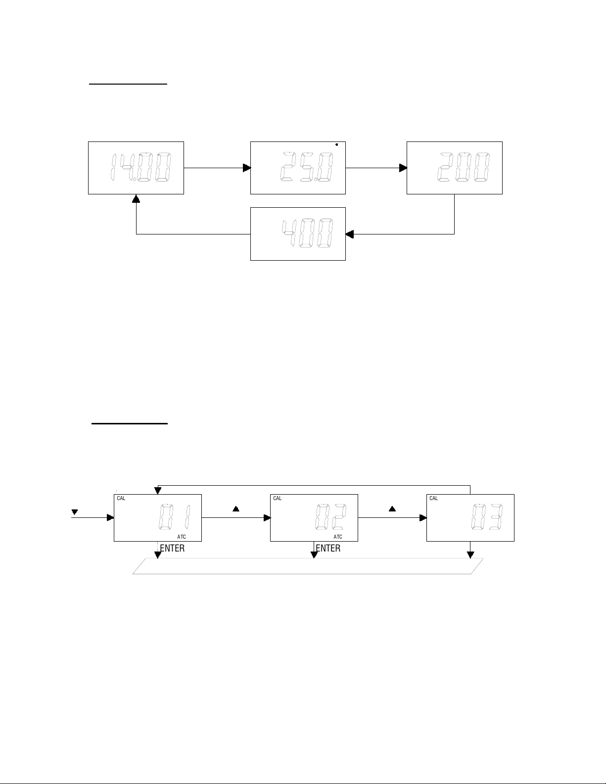
1. Temperature compensation select:
+ENTER
ENTER ENTER ENTER
pH buffer 1 select
CAL
ATC
CAL
ATC
CAL
MAN
Pressing [UP] key or [DOWN] key in this screen will cycle the display from 01 (Thermistor:
10k ohm), 02 (Resistor: PT1000), 03 (Manual) modes above.
Select the preferred temperature compensation mode, press [ENTER] key to save, and
enter the next setting screen.
pg.8
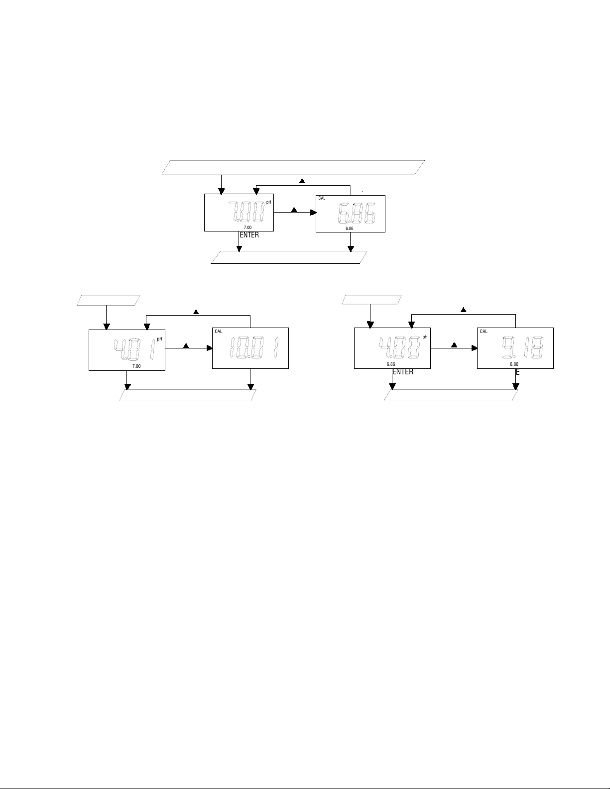
2. pH buffer 1 select:
Pressing [UP] key or [DOWN] key in this screen will cycle the display from 7.00, 6.86 buffer
above.
Select the preferred buffer, press [ENTER] key to save, and enter the next setting screen.
Temperature compensation select
pH buffer 2 select
ENTER
ENTER ENTER
CAL
6.86
pH
CAL
7.00
pH
Buffer 1 7.00
Relay control parameters select
ENTER
CAL
7.00
pH
CAL
7.00
pH
ENTER ENTER
Buffer 2 6.86
Relay control parameters select
ENTER
ENTER ENTER
CAL
6.86
pH
CAL
6.86
pH
Pressing [UP] key or [DOWN] key in this screen will cycle the display from 4.01, 10.01 (or
4.00, 9.18) buffer above.
Select the preferred buffer, press [ENTER] key to save, and enter the next setting screen.
【
Note
】
: The pH buffer 2 is either 4.01 or 10.01 if select 7.00 buffer at pH buffer 1 select
screen. The pH buffer 2 is either 4.00 or 9.18 if select 6.86 buffer at pH buffer 1 select
screen.

pg.9
3. 4 mA output setting:
mA output parameters select
20mA output setting
ENTER
ENTER
CAL CAL
mA
pH
Pressing [UP] key or [DOWN] key in this screen to adjust the 4 mA value, this value is used
for scaling the 4-20mA analog output.
Pressing [ENTER] key to save, and enter the next setting screen.
4. 20mA output setting:
4mA output setting
Measure mode
ENTER
ENTER
CAL CAL
mA
pH
Pressing [UP] key or [DOWN] key in this screen to adjust the 20 mA value, this value is
used for scaling the 4-20mA analog output.
pg.10
E. pH Calibration mode
The TX10 uses 2-point calibration for pH. The first point must be 6.86/7.00, and the second
point can either be 4.00/4.01 or 9.18/ 10.01.
In the pH Measure mode, pressing [UP] key and [ENTER] key at the same time to allow the
meter to go to the pH Calibration mode.
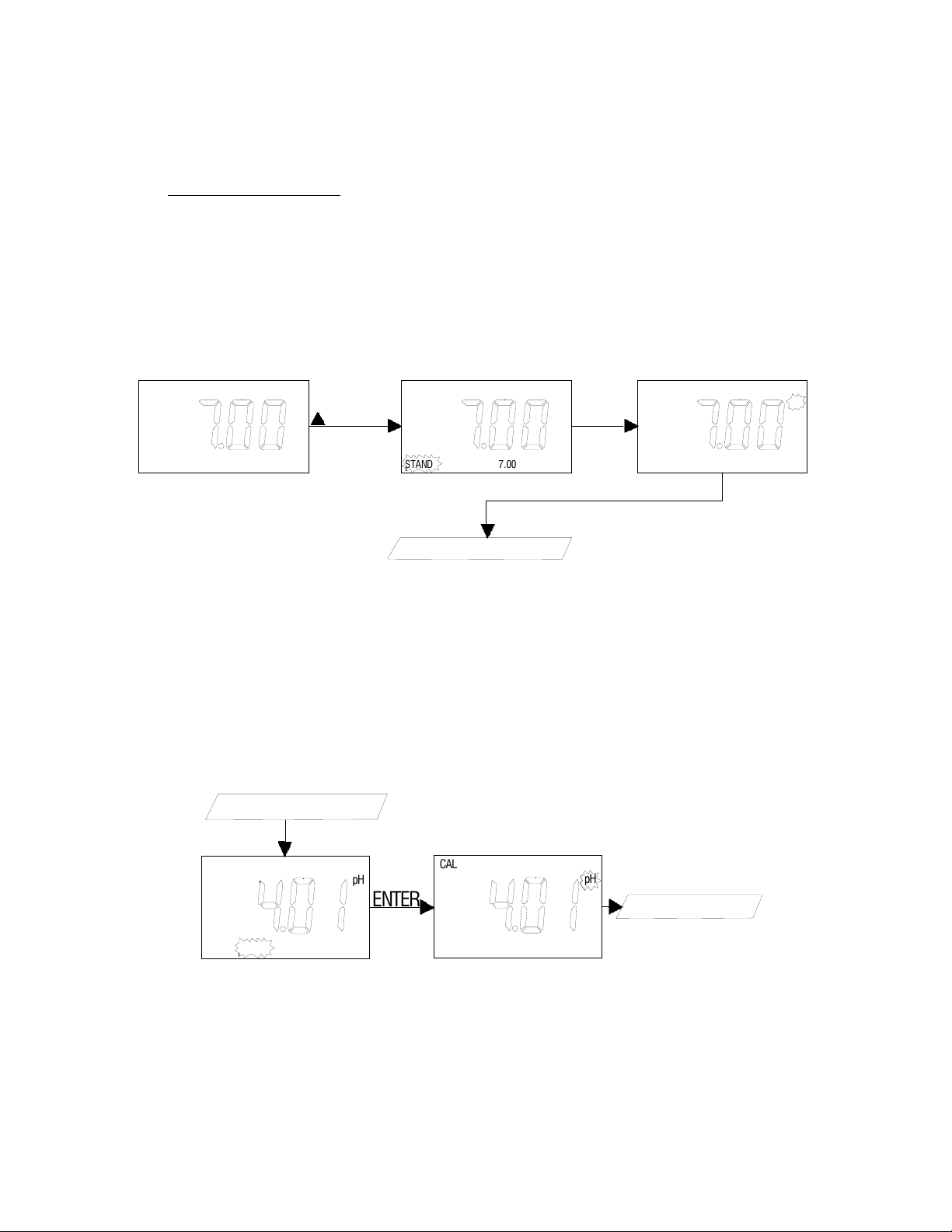
1. Buffer 1 (STAND) calibration:
Buffer 2 calibration
+ENTER ENTER
STAND
CAL
7.00
pH
STAND SLOPE 7.00
pH
HI2
STAND
CAL
7.00
pH
Enter into the pH calibration mode, the “STAND” icon will flash, the unit is ready to be
standardized at the first buffer. Rinse the pH and ATC/Temp probes in distilled water and
immerse them in the first buffer solution (either 7.00 or 6.86). Allow temperature reading
to stabilize, then press “ENTER” key to calibrate. The “pH” icon will flash until the unit
detects a stable reading. Once the unit calibrates the first point, the “SLOPE” icon will
flash. The unit is ready to be sloped at the second buffer.
2. Buffer 2 (SLOPE) calibration:
Rinse the pH and ATC/Temp probe in distilled water and immerse them in the second
buffer solution (either 4.00/4.01 or 9.18/10.01). Allow temperature reading to stabilize,
then press “ENTER” key to calibrate. The “pH” icon will flash until the unit detects a stable
reading. Once the unit calibrates the second point and the unit will automatically exit the
calibration mode and goes to the pH Measure mode. Dual point calibration is complete.
ENTER
Buffer 1 calibration
Measure mode
STAND SLOPE
CAL
7.00
pH
STAND SLOPE
CAL
7.00
pH
pg.11
【
Note
】
: In the Setting mode (1. Temperature compensation select), select 03 (Manual
temperature compensation mode) if no temperature probe is being used. Press the [UP]
key or [DOWN] key in the Manual temperature compensation mode to adjust the
value to that of the test solution temperature. Then calibrate buffer 1 and buffer 2.
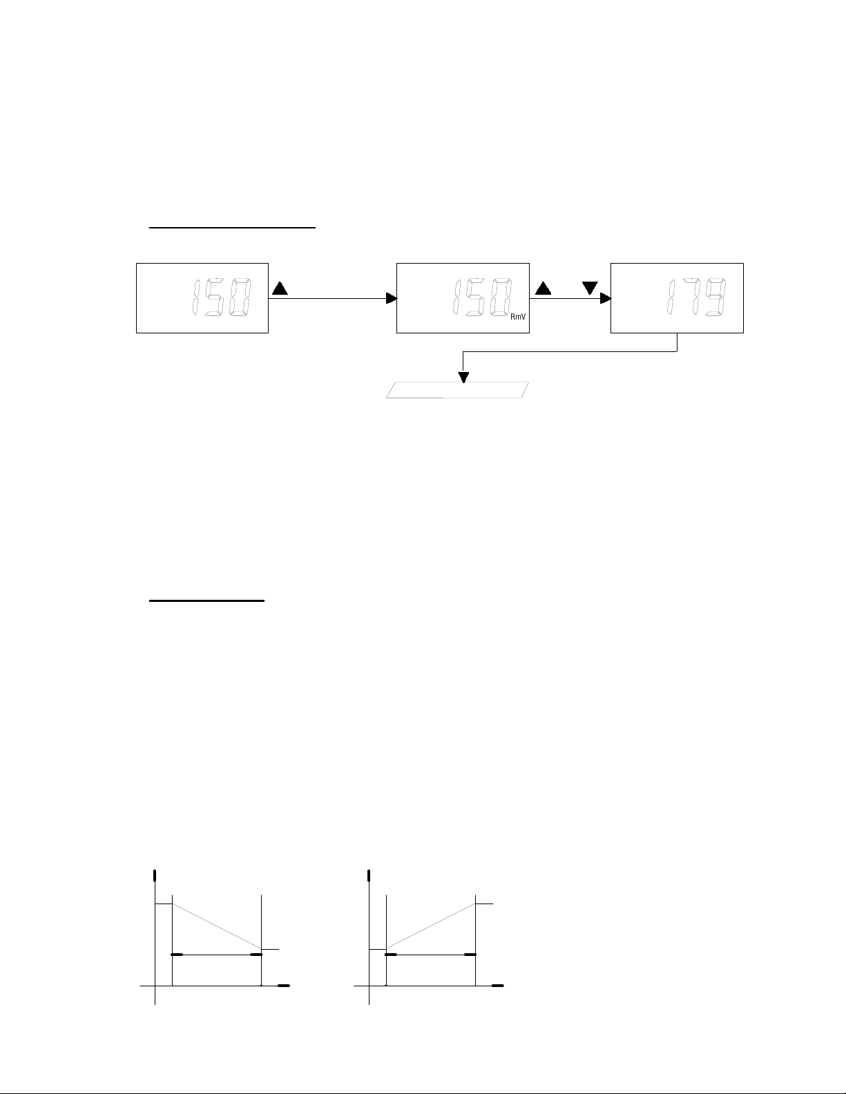
F. RmV Calibration mode
RmV normal mode
or
CAL
RmV
CAL
RmV RmV
+ENTER
The model TX15 uses 1-point calibration for RmV. In the RmV Measure mode, pressing [UP]
key and [ENTER] key at the same time, the meter will enter into RmV calibration mode.
Rinse the ORP probe in distilled water and immerse it in the ORP standard solution, then press
[UP] or [DOWN] key to adjust the ORP value to that the ORP standard. Press [ENTER] key to
save. The unit beeps to indicate a successful calibration. Calibration is now complete and the
unit will automatically switch to the ORP relative mV Measure mode.
【
Note
】
: When the ORP absolute mV reading is off, recalibrate RmV value.
G. 4-20 mA output
1. Isolation voltage:
The maximum isolation voltage of the 4-20mA output contacts is 500 VDC. The voltage
differential between the 4-20mA output contacts and the load should not exceed 500
VDC.
2. Output load:
The maximum load is 500 ohm. Output current inaccuracies may occur for load
impedance in excess 500 ohm.
3. The analog output will produce a linear analog output. The user can only bind the
ANALOG OUTPUT to one reading at a time. The user can change this anytime by
changing option at the Calibration/Setting mode screen.
The analog output will be restricted on the 4 mA setting, 20 mA setting and the current
bound display.
Adjustable
Bandwidth Bandwidth
Adjustable
Set
point point
Set
20mA
4mA 4mA
20mA
mA mA
Decreasing current for Increasing current for
pH/ORP pH/ORP
increasing pH or ORP increasing pH or ORP

pg.12
The above figure shows the relationship between Reading, U4mA & U20mA.
The analog output is based on the following equation:
mA(output) = 4mA+(16mA)*(D – U4mA ) / (U20mA- U4mA)
Where:
mA(output) = analog output
D = current bound display
U
4mA = user setting for 4 mA for current bound display
U
20mA = user setting for 20 mA for current bound display
【
Note
】
:
1. The ideal range of U4mA and U20mA for pH is -2.00 to 16.00 pH.
2. The ideal range of U4mA and U20mA for absolute mV is -2000 to 2000 mV.
3. The ideal range of U4mA and U20mA for relative mV is -3000 to 3000 mV.

pg.13
ERROR DISPLAY AND TROUBLESHOOTING ERVIEW
pH/ORP
Display
Temperature
Display
Display Mode
Possible cause(s)
[Action(s)]
"OvEr" -10.0~120.0°C pH measure mode pH > 16.00pH
[Recalibrate]
“Undr” -10.0~120.0°C pH measure mode pH < -2.00pH
[Recalibrate]
"OvEr" "OvEr" pH measure mode a. Temperature > 120.0°C.
[Bring buffer solution to lower
temperature.]
[Replace temperature probe.]
b. No temperature sensor.
[Adjust the manual temperature to -
10~120°C.]
"OvEr" “Undr” pH measure mode a. Temperature < -10.0°C.
[Bring buffer solution to higher
temperature.]
[Replace temperature probe.]
b. No temperature sensor.
[Adjust the manual temperature to -
10~120°C.]
"OvEr" Temperature
reading
Absolute ORP mV or
relative ORP
Absolute ORP mV > +1999 mV
[Bring solution to a lower ORP reading]
"Undr" Temperature
reading
Absolute ORP mV or
relative ORP
Absolute ORP mV < -1999 mV
[Bring solution to a higher ORP reading]

pg.14
pH/ORP
Display
Temperature
Display
Display Mode
Possible cause(s)
[Action(s)]
ORP
reading
"OvEr" Absolute ORP mV or
relative ORP
a. Temperature > 120.0°C.
[Bring buffer solution to lower
temperature.]
[Replace temperature probe.]
b. No temperature sensor.
[Adjust the manual temperature to -
10~120°C.]
ORP
reading
"Uder" Absolute ORP mV or
relative ORP
a. Temperature < -10.0°C.
[Bring buffer solution to higher
temperature.]
[Replace temperature probe.]
b. No temperature sensor.
[Adjust the manual temperature to -
10~120°C.]
"OvEr" 0~60°C a. pH calibration
mode-Buffer 1
(STAND)-7.00
b. pH calibration
mode-Buffer 1
(STAND)-6.86
c. pH calibration
mode-Buffer 2
(SLOPE)
a. Offset < -100 or > 100 mV
b. Offset < -91.7 or > 108.3 mV
c. Slope > ideal mV by 30%
[Use a new buffer solution.]
[Replace electrode.]
pg.15
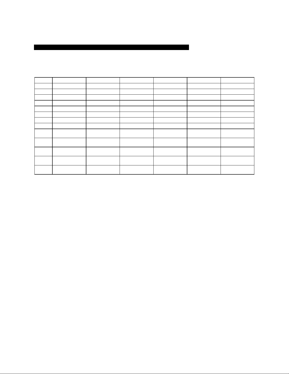
pH BUFFERS
The temperature characteristics of pH calibration buffers pH4.00, pH4.01, pH6.86, pH7.00,
pH9.18 & pH10.01 are stored inside the instrument. The buffers used to calibrate the
instrument must exhibit the same temperature characteristics as the stored values.
°C 4.00 6.86 9.18 4.01 7.00 10.01
0 4.01 6.98 9.46 4.01 7.11 10.32
5 4.00 6.95 9.39 4.01 7.08 10.25
10 4.00 6.92 9.33 4.00 7.06 10.18
15 4.00 6.90 9.28 4.00 7.03 10.12
20 4.00 6.88 9.23 4.00 7.01 10.06
25 4.00 6.86 9.18 4.01 7.00 10.01
30 4.01 6.85 9.14 4.01 6.98 9.97
35 4.02 6.84 9.10 4.02 6.98 9.93
40 4.03 6.84 9.07 4.03 6.97 9.89
45 4.04 6.83 9.04 4.04 6.97 9.86
50 4.06 6.83 9.02 4.06 6.97 9.83
55 4.07 6.83 8.99 4.08 6.97 9.80
60 4.09 6.84 8.97 4.10 6.98 9.78
【Note】: The actual reading of the instrument can differ from the values shown by ±0.01 pH.

pg.16
SPECIFICATIONS
Recognized pH buffers US (4.01, 7.00, 10.01) or NIST (4.00, 6.86, 9.18)
pH Temperature compensation Manual/Auto -10.0°C to 120.0 °C
pH Buffer Temperature range 0.0°C to 60.0 °C
pH Electrode Offset recognition +/-100 mV at pH 7.00 , +108.3 mV/-91.7 mV at pH 6.86
pH Electrode Slope recognition +/- 30% at pH 4.00, 4.01, 9.18, 10.01
Input impedance >1012 Ω
Calibration end point sensing Yes
Temperature sensor Thermistor: 10k ohm at 25 °C, (User selectable) Resistor ( PT1000) or
Manual
Current output range 4 to 20 mA (isolated)
Current output scale user programmable
Maximum load 500 Ω
Accuracy ±0.03 mA
Isolation voltage 500VDC
Keys Audiofeedbackinallkeys
Power: 100VAC to 240VAC , 50/60Hz
Ambient Temperature range 0.0 to 50.0 °C
Case IP65, 1/8DIN case, depth 90mm
Weight 290 g
Mode Range Resolution Accuracy
pH -2.00 to 16.00 pH 0.01 pH ±0.1% ± 1 digit
ORPAbsolute mV -1999 to 1999 mV 1 mV ±0.1% ± 1 digit
ORP Relative mV -2999 to 2999 mV 1 mV ±0.1% ± 1 digit
Temperature -10.0 to 120.0 °C 0.1 °C ±0.3 °C

pg.17
WARRANTY
Sensorex warrants this product to be free from significant deviations in material and
workmanship for a period of 1 year from date of purchase. If repair or adjustment is
necessary and has not been the result of abuse or misuse, within the year period, please
return-freight-prepaid and the correction of the defect will be made free of charge. If you
purchased the item from our Sensorex distributors and it is under warranty, please contact
them to notify us of the situation. Sensorex Service Department alone will determine if the
product problem is due to deviations or customer misuse.
Out-of-warranty products will be repaired on a charge basis.
RETURN OF ITEMS
Authorization must be obtained from one of our representatives before returning items for
any reason. When applying for authorization, have the model and serial number handy,
including data regarding the reason for return. For your protection, items must be carefully
packed to prevent damage in shipment and insured against possible damage or loss.
Sensoex will not be responsible for damage resulting from careless or insufficient packing. A
fee will be charged on all authorized returns.
【
Note
】
:Sensorex reserves the right to make improvements in design, construction and
appearance of our products without notice.
Table of contents
Other Sensorex Controllers manuals


