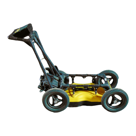
Sensors & Software pulseEKKO Pro User manual

USER’SGUIDE
Copyright 2005 Sensors & Software Inc. 2005-00040-01
pulseEKKO PRO

SENSORS & SOFTWARE INC. PRODUCT LICENCE, COPYRIGHT, LIABILITY AND WARRANTY INFORMATION
Important
Please read this document carefully before removing the SOFTWARE PRODUCT storage media from their protective cover
or assembling the HARDWARE PRODUCT. By removing the storage media or assembling the hardware, you are agreeing
to be bound by the terms of this agreement. If you do not agree to the terms of this agreement, promptly contact Sen-
sors & Software, Inc. at the address indicated at the end of this document.
Definition
The word PRODUCT as used herein defines any tangible item sold by Sensors & Software, Inc. and may be comprised
of HARDWARE PRODUCT which consists of physical objects and SOFTWARE PRODUCT which means computer programs,
codes and related support materials.
Software Product Licence Agreement
In order to preserve and protect its rights under the applicable laws, Sensors & Software, Inc. (hereafter SSI) does not
sell any rights to its Software product. Rather, SSI grants the right to use its software, diskettes (or other storage
media) and documentation (hereafter collectively called SOFTWARE PRODUCT) by means of a SOFTWARE PRODUCT
licence. You acknowledge and agree that SSI retains worldwide title and rights to all its software and that the SOFTWARE
PRODUCT contains proprietary materials protected under copyright, trademark and trade secret laws.
Grant of Software Product Licence
In consideration of payment of the licence fee which is the price you pay for the SOFTWARE PRODUCT and your agree-
ment to abide by the terms and conditions of this Licence Agreement, SSI grants to you, the Licensee, a non-exclusive
right to use the SOFTWARE PRODUCT under the following conditions:
You may:
• use the SOFTWARE PRODUCT on a single workstation owned, leased or otherwise controlled by you
• copy the SOFTWARE PRODUCT for backup purposes in support of your use of the product on a single workstation
You may not:
• copy, distribute or sell copies of the SOFTWARE PRODUCT or accompanying written materials, including modified or
merged SOFTWARE PRODUCT to others
• sell, licence, sublicence, assign or otherwise transfer this licence to anyone without the prior written consent of
SSI
• modify, adapt, translate, decompile, disassemble or create derivative works based on the SOFTWARE PRODUCT
Termination
This licence is effective until terminated. You may terminate the licence at any time by returning the SOFTWARE PROD-
UCT and all copies to SSI. The licence will automatically terminate without notice by SSI if you fail to comply with any
terms or conditions of this agreement. Upon termination, you agree to return all copies of the SOFTWARE PRODUCT to
SSI.
Update Policy
SSI may create, from time to time, updated versions of its SOFTWARE PRODUCT. At its option, SSI will make such
updates available to licencees who have paid the update fee.
Product Warranty, Limited Remedy and Limited Liability
SSI warrants the PRODUCT to be free from defect in material and workmanship under normal use for a period of one
year (365 days) from the date of shipment. Any third party computer systems or other items not manufactured directly
by SSI purchased with any PRODUCT or independently from SSI are subject to the original manufacturer's warranty and
not the responsibility of SSI.
SSI makes no other warranties including, but not limited to, any implied warranty of merchantability or fitness for a par-
ticular purpose. If this product is defective within the warranty period stated above, your exclusive remedy shall be, at
SSI’s option to replace or repair the SSI product or refund the purchase price of the SSI product. Except where prohib-
ited by law, SSI will not be liable for any loss or damage arising from this SSI product, whether direct, indirect, special,
incidental or consequential regardless of the legal theory asserted.

All statements, technical information, and recommendations related to SSI products are based on information believed
to be reliable, but the accuracy or completeness is not guaranteed. Before using this product, you must evaluate it and
determine if it is suitable for your intended application. You assume all risks and liability associated with such use. Any
statements related to the product which are not contained in SSI current publications, or any contrary statements con-
tained on your purchase order shall have not force or effect unless expressly agreed upon, in writing, by an authorized
officer of SSI.
SSI warrants the diskettes or other storage media on which the SOFTWARE PRODUCT is furnished to be free from defects
in material and workmanship under normal use for a period of ninety (90) days from the date of purchase as evidenced
by a copy of your invoice.
Except as specified above, any SOFTWARE PRODUCT is provided "as is" without warranty of any kind, either expressed
or implied, including, but not limited to, the use or result of use of the product in terms of correctness, accuracy, reliabil-
ity, currentness or otherwise. The entire risk as to the results and performance of the PRODUCT is assumed by you. If
the PRODUCT is defective or used improperly, you, and not SSI or its dealers, distributors, agents, or employees,
assume the entire cost of all necessary servicing, repair or correction.
SSI's entire liability and your exclusive remedy for SOFTWARE PRODUCT shall be, at SSI's option, either
• the replacement of any diskette or hardware components which do not meet SSI's Limited Warranty and which are
returned to SSI postage prepaid with a copy of the receipt, or
• if SSI is unable to deliver a replacement diskette which is free of defects in material or workmanship, Licensee
may terminate this agreement and have the licence fee refunded by returning all copies of the SOFTWARE PRODUCT
postage prepaid with a copy of the receipt.
If failure of any PRODUCT resulted from accident, abuse or misapplication, SSI shall have no responsibility to replace
the SOFTWARE PRODUCT, refund the licence fee, or replace or repair the HARDWARE PRODUCT.
Do not tamper with any PRODUCT. PRODUCT contains no user serviceable parts. If tampering is evident in SSI’s
opinion, warranty is void and null.
No oral or written information or advice given by SSI, its dealers, distributors, agents or employees shall create a war-
ranty or in any way increase the scope of this warranty and you may not rely on any such information or advice.
Neither SSI nor anyone else who has been involved in the creation, production or delivery of the PRODUCT shall be lia-
ble for any direct, indirect, special, exemplary, incidental or consequential damages, claims or actions including lost
information, lost profits, or other damages arising out of the use or inability to use this PRODUCT even if SSI has been
advised of the possibility of such damages.
This warranty gives you specific rights. You may have other rights which vary from province to province, territory to ter-
ritory and certain limitations contained in this limited warranty may not apply to you.
General
pulseEKKO®, Noggin®, SpiView®, Conquest®and SnowScan®are registered trademarks of SSI. No right, licence, or
interest to such trademarks is granted hereunder with the purchase of the PRODUCT or the SOFTWARE PRODUCT licence.
Governing Law
In the event of any conflict between any provision in this licence agreement and limited warranty and any applicable
provincial legislation, the applicable provincial legislation takes precedence over the contravening provision. This
agreement shall be governed and construed in accordance with the laws of the Province of Ontario, Canada.
Serviceability
Should any term of this agreement be declared void or not enforceable by any court of competent jurisdiction, the
remaining terms shall remain in full effect.
Waiver
Failure of either party to enforce any of its rights in this agreement or take action against any other party in the event of
a breach of this agreement shall not be considered a waiver of the right to subsequent enforcement of its rights or
actions in the event of subsequent breaches by the other party.

Acknowledgement
You acknowledge that you have read this agreement, understand it and agree to be bound by its terms and conditions.
You further agree that this agreement is the complete and exclusive statement of agreement between the parties and
supersedes all proposals or prior agreements oral or written between the parties relating to the subject matter of this
agreement.
Should you have any questions concerning this agreement, please contact in writing:
Sensors & Software Inc.
1040 Stacey Court
Mississauga, Ontario
Canada L4W 2X8
Tel:(905) 624-8909
Fax:(905) 624-9365
E-mail: radar@sensoft.ca
pulseEKKO, Noggin, SpiView, SnowScan, Conquest, SmartCart, SmartHandle, Conquest for Windows, Win_EKKO, EKKO_Mapper,
EKKO_3D and EKKO_Pointer are Trademarks of Sensors & Software Inc

pulseEKKO PRO Table of Contents
i
Table of Contents
1 Overview ............................................................................................................1
2 System Assembly and Startup .............................................................2
2.1 System Configurations.................................................................................2
2.1.1 Low Frequency Hand Held ..............................................................2
2.1.2 High Frequency Hand Towed..........................................................3
2.2 DVL and Control Module .............................................................................4
2.2.1 Attaching the Control Module to the DVL........................................4
2.2.2 Attaching the Fibre Optic Converters for Low frequency Antennas5
2.3 Low Frequency Transmitter, Receiver and Antenna Assembly..................6
2.3.1 Low Frequency Antennas................................................................6
2.3.2 Attaching the Sockets to the Transmitter and Receiver..................7
2.3.3 Inserting Pins into the Antennas......................................................7
2.3.4 Attaching the Mounting Blocks to the Antennas .............................8
2.3.5 Latching the Transmitter and Receiver to the Mounting Blocks .....9
2.3.6 Inserting Batteries into the Transmitter and Receiver...................10
2.3.7 Attaching Handles..........................................................................11
2.3.7.1 Attaching the Adjustable Handles ..........................................11
2.3.8 Connecting the Fibre Optic Cables ...............................................12
2.4 High Frequency Transducer Assembly .....................................................14
2.4.1 High Frequency Transducers ........................................................14
2.4.2 Mounting Transducers to the Skid Plate .......................................15
2.4.3 High Frequency Hand-Towed System ..........................................16
2.4.3.1 Attaching the Adjustable Tow Handle.....................................16
2.4.3.2 Attaching the Big Wheel Odometer ........................................17
2.4.3.3 Connecting the Odometer Cable to the Control Module...........18
2.4.3.4 Connecting the Transducer Cables ........................................19
2.5 Adding Accessories ...................................................................................20
2.5.1 Electrical Beeper/Trigger Unit........................................................20
2.5.2 Fibre Optic Beeper/Trigger Unit.....................................................20
2.5.3 DVL Carrier ....................................................................................23
2.5.4 Odometers .....................................................................................23
2.5.5 GPS................................................................................................24
2.6 Starting the pulseEKKO PRO System.......................................................25

Table of Contents pulseEKKO PRO
ii
2.6.1 Powering the DVL and Control Module.........................................25
2.6.2 Powering the Low Frequency Transmitter and Receiver..............26
2.6.3 Digital Video Logger ......................................................................26
2.6.4 Main Menu .....................................................................................27
2.6.5 Using the Software Menus ............................................................30
3 System Setup Parameters .....................................................................31
3.1 System Parameters for a Quick Start to Data Collection..........................32
3.2 GPR Parameters........................................................................................33
3.2.1 Antenna Frequency .......................................................................34
3.2.2 Time Window .................................................................................35
3.2.2.1 How Depth is Determined .....................................................35
3.2.3 Temporal Sampling Interval...........................................................36
3.2.3.1 Determining the Number of Points per Trace ..........................36
3.2.4 Antenna Separation .......................................................................37
3.2.5 Antenna Step Size .........................................................................38
3.2.6 Radar Velocity................................................................................39
3.2.7 System Stacking ............................................................................40
3.2.8 Pulser Setting.................................................................................41
3.3 Acquisition Control.....................................................................................42
3.3.1 Trigger Method...............................................................................42
3.3.1.1 Triggers ...............................................................................43
3.3.1.2 Odometer.............................................................................43
3.3.1.3 Free Run..............................................................................43
3.3.2 Beeper Activated............................................................................43
3.3.3 Free Run Trace Delay ...................................................................44
3.3.4 GPS Parameter Menu ...................................................................44
3.3.4.1 GPS Recording Mode ...........................................................45
3.3.4.2 Baud Rate............................................................................47
3.3.4.3 Stop Bits ..............................................................................47
3.3.4.4 Data Bits ..............................................................................47
3.3.4.5 Parity ...................................................................................47
3.3.4.6 Last NMEA String .................................................................47
3.3.4.7 Test GPS with Listing............................................................48
3.3.4.8 Test GPS with Plotting ..........................................................48
3.3.5 Odometer Setup Menu ..................................................................48
3.3.5.1 Odometer Calibration............................................................48

pulseEKKO PRO Table of Contents
iii
3.3.5.2 Set Odometer Manually ........................................................49
3.3.5.3 Odometer Direction...............................................................49
3.3.6 Fibre Optic Testing.........................................................................49
3.4 Survey Parameters ....................................................................................50
3.4.1 Start Position..................................................................................50
3.4.2 Antenna Step Size .........................................................................50
3.4.3 Positional Units ..............................................................................50
3.4.4 Data Directory Number ..................................................................51
3.4.5 Survey Type...................................................................................51
3.4.6 GPR Grid Type ..............................................................................51
3.4.7 X Line Spacing...............................................................................55
3.4.8 Y Line Spacing...............................................................................55
3.5 Display Parameters....................................................................................56
3.5.1 Trace Plotting Type........................................................................56
3.5.2 Gain Type Applied and Gain Applied ............................................58
3.5.2.1 AGC Gain ............................................................................58
3.5.2.2 SEC Gain.............................................................................60
3.5.2.3 Constant Gain ......................................................................61
3.6 DVL Setup Menu........................................................................................63
3.6.1 Set DVL Time and Date.................................................................63
3.6.2 Set DVL Transfer Mode.................................................................63
3.6.3 Set DVL into Upgrade Mode..........................................................63
3.6.4 Select Display Info Mode...............................................................64
3.7 View Complete Setup ................................................................................64
3.8 Return ........................................................................................................64
4 Running in Scope Mode .........................................................................65
4.1 Scope Screen ............................................................................................66
4.1.1 Adjusting Timezero (Offset)...........................................................66
5 Data Collection Mode ...............................................................................69
5.1 Data Directory ............................................................................................69
5.2 Select Line Number ...................................................................................69
5.3 Data Collection...........................................................................................70
5.4 Fiducial Markers.........................................................................................72
5.4.1 Fiducial Markers for Rubberbanding .............................................73

Table of Contents pulseEKKO PRO
iv
5.4.2 Fiducial Markers for GPS...............................................................73
5.5 Data Collection Pause Menu .....................................................................73
5.5.1 Exit .................................................................................................73
5.5.2 Continue.........................................................................................73
5.5.3 Scale ..............................................................................................73
5.5.4 Calib - Velocity Calibration.............................................................75
5.5.4.1 Hyperbola Matching..............................................................75
5.5.4.2 Identifying Air Reflections ......................................................77
5.5.4.3 Target of Known Depth .........................................................78
5.6 Collect Grid Data........................................................................................79
5.6.1 Select Line Direction......................................................................79
5.6.2 Select Grid Line Number ...............................................................79
5.7 View Previously Collected Lines................................................................80
5.8 Collect Data (No Save) ..............................................................................81
6 Surveying Techniques .............................................................................82
6.1 Low Frequency Reflection (Profiling) Mode ..............................................82
6.1.1 Two Person Operation...................................................................82
6.1.2 One Person Operation...................................................................83
6.1.3 Strain Relief for Fibre Optic Cables...............................................84
6.1.4 Maintaining Proper Antenna Separation .......................................84
6.1.5 Antenna Movement........................................................................85
6.2 High Frequency Reflection (Profiling) Mode .............................................85
6.2.1 Tow Mode Operation .....................................................................85
6.3 Antenna Orientation...................................................................................86
6.4 Triggers ......................................................................................................87
6.5 Free Run ....................................................................................................87
6.6 Odometer Data Acquisition........................................................................88
6.6.1 Skipping Traces .............................................................................88
6.6.2 Backing up to Pinpoint Target Positions........................................89
6.7 Signal Polarity ............................................................................................89
6.8 Spatially Aliasing the Data.........................................................................89
6.9 Creating a Test Line for Data Quality ........................................................90
6.10 Adding GPS for Positioning .......................................................................90
6.11 Common Mid-Point (CMP) Survey ............................................................91
6.12 Transillumination Surveys..........................................................................93

pulseEKKO PRO Table of Contents
v
6.12.1 Borehole GPR................................................................................93
6.12.2 Walls, Pillars and Monument Surveys...........................................94
7 Troubleshooting ..........................................................................................95
7.1 Power Supply.............................................................................................96
7.1.1 DVL and Control Module Power Requirements ............................96
7.1.2 Transducer Power Requirements..................................................97
7.1.3 Transmitter and Receiver Power Requirements ...........................97
7.1.4 Testing Transmitter and Receiver Batteries..................................98
7.2 Testing Fibre Optic Cables ........................................................................99
7.3 Control Module Related Errors ................................................................101
7.4 Receiver Related Errors ..........................................................................101
7.5 Transmitter Problem: No Signal on Screen.............................................101
7.6 System Overheating ................................................................................102
7.7 DVL Problem............................................................................................102
7.8 Timezero Jitter .........................................................................................102
7.9 System Runs But Data Does Not Look Right..........................................103
7.10 Contacting Sensors & Software Inc.........................................................103
8 File Management .......................................................................................104
8.1 Connecting the DVL to a PC ...................................................................105
8.2 Installing and Running the WinPXFER Software on a PC......................106
8.3 Transfer Directory ....................................................................................106
8.4 Transfer File.............................................................................................107
8.5 Delete Directory .......................................................................................108
8.6 Delete File ................................................................................................109
8.7 View Disk Space ......................................................................................110
8.8 Viewing Data Files on the External PC ...................................................110
9 Care and Maintenance ...........................................................................111
9.1 General ....................................................................................................111
9.2 Electronic Spares.....................................................................................111
9.3 Radar Unit ................................................................................................112
9.4 Antenna Electronics Connection Pins .....................................................112
9.5 Fibre Optics Cables .................................................................................112
9.6 Fibre Optics Cable Repair .......................................................................113

Table of Contents pulseEKKO PRO
vi
10 Helpful Hints ................................................................................................117
10.1 Batteries ...................................................................................................117
10.2 Measuring Position ..................................................................................117
10.3 Data Files .................................................................................................117
10.4 Spares......................................................................................................117
Appendix A: Data File Formats.................................................................. A-1
Appendix B: GPR Signal Processing Artifacts ...................................... B-1
Appendix C: Excerpts from the HP Fiber Optic Handbook................ C-1
Appendix D: Health & Safety Certification .............................................D-1
Appendix E: FCC Regulations .................................................................. E-1
Appendix F: Instrument Interference ....................................................... F-1
Appendix G: Safety Around Explosive Devices ....................................G-1

pulseEKKO PRO 1-Overview
1
1 Overview
This manual describes how to set up and run a pulseEKKO PRO LF (low frequency) Ground Penetrating
Radar (GPR) system connected to a Digital Video Logger (DVL) for data display and storage.
System Assembly Section 2 System Assembly and Startup on page 2 details the
& Startup: step by step procedure for assembling the pulseEKKO PRO system. It also
describes how to start up the DVL and navigate around the menus.
Setting Data Collection Section 3 System Setup Parameters on page 31 covers the procedure for
Parameters: selecting appropriate data collection parameters. Although every effort has
been made to make the software as transparent and user friendly as possible,
this section explains in greater detail each of the options and menu items in
the data collection program.
To get up and running quickly see Section 3.1 System Parameters for a Quick
Start to Data Collection on page 32.
Scope Mode: Section 4 Running in Scope Mode on page 65 describes how to set timezero
to ensure the system is ready for data collection.
Data Collection: Section 5 Data Collection Mode on page 69 describes running the radar sys-
tem and collecting data.
Surveying Techniques: Section 6 Surveying Techniques on page 82 describes system configurations
and offers hints for properly collecting data in field conditions.
Troubleshooting: Section 7 Troubleshooting on page 95 presents some simple steps the user
should go through when things do not work as they should.
File Management: Section 8 File Management on page 104 describes how to transfer data from
the DVL to a PC and how to delete files and directories from the DVL.
Care and Maintenance: Section 9 Care and Maintenance on page 111 discusses procedures for the
care and maintenance of your pulseEKKO PRO system.
Helpful Hints: Section 10 Helpful Hints on page 117 lists some helpful hints, based on years
of experience, to help make data collection and field operations run as
smooth as possible.

2-System Assembly and Startup pulseEKKO PRO
2
2 System Assembly and Startup
2.1 System Configurations
The modular design of the pulseEKKO PRO GPR makes the system very flexible and readily field-portable
in a number of configurations. This section details the steps for assembling the Low Frequency Hand Held
(Figure 2-1) and High Frequency Hand Towed (Figure 2-2) configurations.
2.1.1 Low Frequency Hand Held
There are four essential components to the low frequency radar system: the Digital Video Logger (DVL),
the control module, the transmitter assembly and the receiver assembly. The control module is attached to

the back of the DVL. The transmitter and receiver assemblies are connected to the control module via
appropriate fibre optics cables (Figure 2-1).
Complete system configurations for data acquisition are shown later (Section 6.1: P82).
Figure 2-1: The complete low frequency pulseEKKO PRO hand held Assembly

pulseEKKO PRO 2-System Assembly and Startup
3
2.1.2 High Frequency Hand Towed
There are four essential components to the high frequency radar system: the Digital Video Logger (DVL),
the control module, the transmitting transducer and the receiving transducer. The control module is
attached to the back of the DVL. The transducers are connected to the control module via the transducer
cables (Figure 2-2).
Figure 2-2: The complete high frequency pulseEKKO PRO tow mode assembly.

2-System Assembly and Startup pulseEKKO PRO
4
2.2 DVL and Control Module
The DVL and Control Module are common to all configurations.
2.2.1 Attaching the Control Module to the DVL
The control module unit must be attached to the back of the DVL (Figure 2-3). This may already have been
done at the factory. Proceed to the next section, if this is the case.
Figure 2-3: The DVL with the control module attached to the back.
Figure 2-4: Remove the 4 yellow caps and the 4 screws from the back of the DVL (left) and place the control module on the back
of the DVL (right). Make sure that the 37 pin connector is aligned properly with the 37 socket connector on the control module.

pulseEKKO PRO 2-System Assembly and Startup
5
Figure 2-5: Attach the control module to the DVL using the 4 screws supplied (left) and a Phillips screwdriver (not supplied).
Tighten the 37 pin connectors into place (right) with a small slotted screwdriver (not supplied).
2.2.2 Attaching the Fibre Optic Converters for Low frequency Antennas
Low frequency, unshielded antennas in the frequency range from 12.5 to 200 MHz require fibre optic
cables to connect the transmitter and receiver to the control module. Higher frequency, shielded antennas
use electrical cables to connect the transmitter and receiver to the control module. The control module is
designed to accept both types of cables.
For low frequency antennas, the Electronic to Fibre Optic Converters must be attached to the control
module and secured using the latches (Figure 2-6).
Figure 2-6: Low frequency antennas (12.5 to 200 MHz) require the electrical to fibre optic converters to be attached to the con-
trol module and secured using the latches.

2-System Assembly and Startup pulseEKKO PRO
6
2.3 Low Frequency Transmitter, Receiver and Antenna Assembly
2.3.1 Low Frequency Antennas
The pulseEKKO PRO can be used with many different antennas. There are 5 low frequency, unshielded,
bistatic antennas available: 12.5, 25, 50, 100 and 200 MHz (Figure 2-7). The best frequency of antenna to
use on a survey depends on the survey objectives (Section 3.2.1: P34).
Figure 2-7: Low frequency, unshielded, bistatic antennas available for the pulseEKKO PRO. The antennas come in pairs; one
transmitting antenna and one receiving antenna. The shortest antennas, the 200 MHz, are 0.5 metres long while the longest, the
12.5 MHz are 8 metres long.
The procedure for attaching the transmitter and receiver to any low frequency antenna is outlined below.

pulseEKKO PRO 2-System Assembly and Startup
7
2.3.2 Attaching the Sockets to the Transmitter and Receiver
Insert and tighten the two female brass antenna sockets into the bottom of the transmitter and receiver
electronic boxes (Figure 2-8). Tighten the sockets finger-tight. DO NOT APPLY UNDUE FORCE!
Figure 2-8: Hand tighten the brass sockets into the bottom of the transmitter and receiver.
2.3.3 Inserting Pins into the Antennas
Insert the two male brass antenna pins into the two threaded holes in the center of the antennas. Tighten
the pins finger-tight (Figure 2-9). DO NOT APPLY UNDUE FORCE!
Figure 2-9: Insert the male brass antenna pins into the holes on the top of the antenna and finger-tighten.

2-System Assembly and Startup pulseEKKO PRO
8
2.3.4 Attaching the Mounting Blocks to the Antennas
Attach the antenna mounting blocks to the antennas by using the flathead screwdriver to tighten the 4
(four) quarter-turn fasteners, ensuring that the male brass antenna pins protrude up the center holes of the
mounting blocks (Figure 2-10). Quarter-turn fasteners work by aligning the screw in the socket and then
pressing downward and tightening a quarter of a turn. DO NOT APPLY UNDUE FORCE. It is usually best
to have all four of the quarter-turn fasteners properly aligned in their sockets before tightening them. To do
this, put slight pressure on the quarter-turn fastener and rotate it until you feel it drop into the socket. Then
align the other three quarter-turn fasteners in the same manner. Once complete, go back and tighten all of
them.
Figure 2-10: Attach the mounting blocks to the top of the antenna using the 4 quarter-turn fasteners. Before doing so, make sure
that the 2 male brass antenna pins have been screwed into the top of the antenna first.

pulseEKKO PRO 2-System Assembly and Startup
9
2.3.5 Latching the Transmitter and Receiver to the Mounting Blocks
Carefully place the transmitter and receiver electronic boxes down onto the mounting blocks such that both
brass pins fully connect (Figure 2-11 Left). Then use the 2 plastic draw latch connectors to hold the
electronics boxes onto the mounting block (Figure 2-11 Right).
Figure 2-11: Attaching the Transmitter and Receiver to the antennas.

2-System Assembly and Startup pulseEKKO PRO
10
2.3.6 Inserting Batteries into the Transmitter and Receiver
With the transmitter and receiver power switched OFF, unlatch the 2 battery covers on the sides of the
electronics and open (Figure 2-12). Place one 12-volt battery on each side on the electronics boxes
making sure the positive (+) terminal faces inward toward the electronics (Figure 2-13). The battery is
“keyed” with a notch in one side so it only fits properly in this orientation. Close and latch the battery
covers.
Figure 2-12: Opening the battery compartment doors.
Figure 2-13: Insert the 12 Volt battery into the battery compartment making sure that battery polarity is correct. The positive (+)
terminal faces inward. The battery is “keyed” so it will only seat properly in the compartment if it is in the correct orientation.
Other manuals for pulseEKKO Pro
1
Table of contents
Other Sensors & Software Radar manuals

Sensors & Software
Sensors & Software LMX200 Series User manual

Sensors & Software
Sensors & Software pulseEKKO User manual

Sensors & Software
Sensors & Software Noggin 100 User manual

Sensors & Software
Sensors & Software LMX100 User manual

Sensors & Software
Sensors & Software CONQUEST 100 User manual

Sensors & Software
Sensors & Software Conquest Series User manual