MicRadar R60ATR2 User manual

Bio-sensing radar
60G Milimeter wave
MicRadar Technology (Shenzhen) Co. ,LTD
R60ATR2-Single track module using guide
Please read the product instructions carefully before use and keep
them properly V1.0

R60ATR2-Single track module using guide
1
501, West Block, Phase II, Tian 'an Innovation Technology Plaza, Futian District, Shenzhen
1. Product description
The trajectory tracking radar detects the presence and position of
basic personnel based on the amplitude, distance, and angle of personnel
movement, including subtle amplitudes such as breathing movements. By
judging the change of the distance and angle of the personnel through the
change of the radar echo in real time, the real-time reporting of the
position of the personnel is realized, and the trajectory tracking effect
is realized. According to the magnitude of the movement (sign size) and
the weak human breathing micro-motion signal, it can identify the
static/active situation of the target, and output a stable static position
locking function.
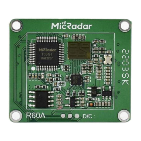
2. Appearance introduction
3. Main performance description
3.1. Main functions of radar
function points
State change time/function explanation
DP1: Real-time distance change
Report distance information once in 1s
DP2: Real-time angle change
1s reporting angle information

R60ATR2-Single track module using guide
2
501, West Block, Phase II, Tian 'an Innovation Technology Plaza, Futian District, Shenzhen
4. Module package size and pin description
Radar module structure diagram Pin description
Note:
1) GP1~GP6 are parameter selection control terminals, which can be
redefined according to user needs.
2) The output signals of this interface are all 3.3V level.
Use wiring diagrams Module wiring diagram
5. Tool preparation
5.1. TTL serial port tool, DuPont line, PC computer, serial port
assistant terminal
5.2. Radar User Manual (Protocol)
6. Power-up and data rules

R60ATR2-Single track module using guide
3
501, West Block, Phase II, Tian 'an Innovation Technology Plaza, Futian District, Shenzhen
7. Radar Installation Instructions
7.1. Working range of radar module
The beam coverage of the R60ATR2 radar module is shown in the figure
below. The radar coverage is a three-dimensional sector area of 100°
horizontal and 100° elevation.
Schematic diagram of R60ATR2 radar coverage area
7.2. Radar installation direction and detection range
7.2.1 Horizontal installation
*To ensure the accuracy of radar detection, please install it
horizontally!
The radar is installed horizontally to ensure that the main beam of
the radar covers the detection area; the recommended installation
height of the radar is 1m≤H≤1.5m, and it is recommended to install
1.4m by default. There are no obvious obstructions and coverings in
front of the radar.
Affected by the installation height of the radar and the range of the
radar beam, in this installation mode, the maximum distance of motion
trajectory tracking is L3 ≈ 10 meters; the maximum distance of human
static position detection is L2 ≈ 6 meters.

R60ATR2-Single track module using guide
4
501, West Block, Phase II, Tian 'an Innovation Technology Plaza, Futian District, Shenzhen
8. Key Functional Testing Guidelines
Motion track tracking test:
Track tracking real-time test:
When the mobile test is performed within the radar detection range, the radar will
report the real-time angular distance change information of the target every second,
and form a real-time trajectory through the real-time position.
carry out testing
Move freely within a certain distance
When judging whether the radar can
normally report the real-time angular
distance change information of the target
every second, if the output can be judged
normally, it means "pass"
Example test table format:
Testing
frequency
move
Is the location report
normal?
pass
the first
time
move freely
Yes
pass
Static position detection test:
Static distance information accuracy test:
The mobile test is carried out within the radar detection range, and when it stops
at a random position, the distance reported by the radar at the end is compared with
the actual distance to confirm whether the distance error value is within a reasonable
range to confirm the accuracy of the distance information.
carry out testing
Move freely within the range for a certain
Judge whether the error between the last
reported distance of the radar and the

R60ATR2-Single track module using guide
5
501, West Block, Phase II, Tian 'an Innovation Technology Plaza, Futian District, Shenzhen
distance and then stop at any position
actual distance is within the specified
accuracy range, within the specified
accuracy range, it means "pass"
Example test table format:
Testing
frequency
Radar distance
information
Compared with real distance
information
Whether it is within the
accuracy requirements
pass
the first
time
2.1m
Yes
pass
Static angle information accuracy test:
The mobile test is carried out within the radar detection range, and when it stops
at a random position, the last angle reported by the radar is compared with the real
angle to confirm whether the distance error value is within a reasonable range to
confirm the accuracy of the distance information.
carry out testing
Move freely within the range for a certain
distance and then stop at any position
Determine whether the error between the
angle finally reported by the radar and
the real angle is within the specified
accuracy range, and within the specified
accuracy range, it means "pass"
Example test table format:
Testing
frequency
Radar angle
information
Compared with real distance
information
Whether it is within the
accuracy requirements
pass
the first
time
50°
Yes
pass
9. Guide to the actual installation steps of the radar
Step 1: Confirm the main activity and stay area of the person, which is the coverage
area of the radar
Step 2: Confirm the actual horizontal installation height of the radar is 1.2m-1.5m
Step 3: Confirm whether there is an interference source within the radar detection
range , and remove the interference source as much as possible
Step 4: Follow the steps to confirm the final installation location for normal use
10.Layout Requirements for Antenna and Housing
PCBA: Need to keep the height of the radar patch ≥ 1mm than other devices

R60ATR2-Single track module using guide
6
501, West Block, Phase II, Tian 'an Innovation Technology Plaza, Futian District, Shenzhen
Shell structure: It is necessary to maintain a distance of 3mm between the
radar antenna surface and the shell surface
Shell detection surface: non-metallic shell, need to be straight, avoid
curved surface, affect the performance of the entire scanning area.
11.Common problem
Interference factors: Radar is an electromagnetic wave detection sensor,
and active non-living will cause false alarms. The movement of metals,
liquids, can lead to false positives. Usually, electric fans, pets close
to the radar, and the shaking of metal curtains can cause false positives.
Radar needs to be planned in terms of installation angle.
Non-interfering factors: radar electromagnetic waves will penetrate human
clothing, curtains, thin wood, and glass. The installation angle and
performance of the radar need to be determined according to the application.
Semi-interference factor: Radar judges the existence of human body and is
not suitable for directly facing the air conditioner. The motor inside the
air conditioner can cause the radar to misjudge. It is required that the
radar product does not directly face the air conditioner. Or in the same
direction as the air conditioner.
12.Historical version update instructions
Revision
Release Data
Summary
V1.0_0520
2022/05/20
first draft
Table of contents
Other MicRadar Radar manuals
Popular Radar manuals by other brands
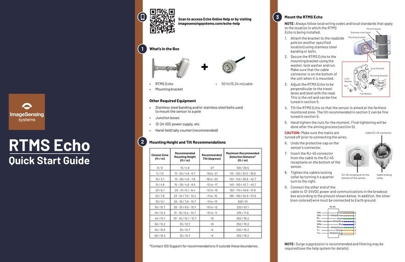
Image Sensing Systems
Image Sensing Systems RTMS Echo quick start guide

Endress+Hauser
Endress+Hauser Micropilot FMR67B operating instructions
OTT
OTT SVR 100 operating instructions

Hesai
Hesai PandarQT quick start guide

Endress+Hauser
Endress+Hauser Micropilot M FMR240 operating instructions

Ainstein
Ainstein WAYV Air user manual
