SPX Radiodetection SENSORS & SOFTWARE LMX150 User manual


ii

Warranty Confirmation
iii
Warranty Confirmation
Return this card within 60 days of purchase to confirm your warranty. You can mail it to
Sensors & Software, fax it to +1-905-624-9365, or register your product online at
www.sensoft.ca/product-registration.
Name:
Company Name:
Address:
City:
State/Province:
Zip Code:
Country:
e-mail:
Phone:
Fax:
Component Serial Numbers (refer to packing list or the sticker on the component)
Comp:
Serial #
Comp:
Serial #
Comp:
Serial #
Comp:
Serial #
Comp:
Serial #
Comp:
Serial #
Comp:
Serial #
Comp:
Serial #
Comp:
Serial #
Comp:
Serial #
Vendor Name:
Date Received:

Warranty Confirmation
iv

v
End User License Agreement
Please read the End User License Agreement at https://www.sensoft.ca/producteula/
Product Warranty and Limited Liability
Please refer to the terms and conditions included as part of your order acknowledgement and/or
invoice for full details of the product warranty and limited liability.
Important Safety Information
Use the Display Unit only as specified in these operating instructions, or the protection provided
by the unit may be impaired.
The battery charger/AC adapter must only be connected to a power outlet which provides a
protective earth (ground).
Connect the AC power cord only to designated power sources as marked on the battery
charger/AC adapter.
The battery charger/AC adapter is rated for indoors use only.
Do not replace detachable MAINS supply cords for the battery charger/AC adapter by
inadequately RATED cords.
Do not position the Display Unit such that it is difficult to disconnect the 37-pin GPR connector.
The exterior of this product should be cleaned using a damp cloth.
Safety Symbols
Consult this documentation in all cases where this safety symbol appears. This
symbol is used to inform you of any potential HAZARD or actions that require your attention.
Do not attempt to open or dismantle any part of this equipment unless directed specifically by
this manual. Doing so may render the equipment faulty and may void the manufacturer’s
warranty.
Use authorized accessories only. Incompatible accessories may damage the equipment or give
inaccurate readings.
Follow your company and national safety procedures and or requirements when operating this
equipment in any environment or workplace. If you are unsure what policies or procedures
apply, contact your company or site’s occupational health and safety officer or your local
government for more information.

Overview
vi

vii
Table of Contents
1. Overview .............................................................................................................11
2. Assembly ............................................................................................................13
2.1 Out of the box 13
2.2 External GPS (optional) 17
2.3 Fully Assembled 19
3. Getting Started ...................................................................................................21
3.1 Powering Up 21
3.2 Shutting Down 22
3.3 Interacting with the Display Unit 22
3.4 Swipe Down Menu 23
4. Tools & Setup.....................................................................................................25
4.1 Preferences 25
4.1.1 Language / Locale 26
4.1.2 Units 26
4.1.3 Date/Time 26
4.1.4 Volume 26
4.1.5 Brightness 27
4.1.6 Wi-Fi Network 27
4.1.7 Email 28
4.1.8 Screen Saver 33
4.1.9 GPR Plot Options 33
4.1.10 Reset to Defaults 34
4.2 System Test 35
4.2.1 System Information 35
4.2.2 Keypad 36
4.2.3 Audio 37
4.2.4 Touch Screen 38
4.2.5 GPR Sensor 38
4.2.6 Odometer 39
4.2.7 GPS 41
4.3 File Management 44
4.3.1 Screenshot Gallery 45
4.3.2 Delete Project 46
4.3.3 Map View 46
4.3.4 Export Data 46
5GPR Concepts.......................................................................................................47
5.1 Theory 47
5.2 Hyperbolas 47
5.3 Calculating Depth 48
5.4 Soil Calibration values 48
5.5 Air Waves 49
6Line Scan...............................................................................................................51
6.1 Selecting a line 51
6.2 Acquiring Data 53
6.3 DynaQ®54
6.4 Back-up Indicator 54
6.5 Flags 56
6.6 Line Scan menu options 57

Table of Contents
viii
6.6.1 Zoom 57
6.6.2 Color 59
6.6.3 Filter 59
6.6.4 Gain 60
6.6.5 Soil Cal 61
6.6.6 Interp 63
6.6.7 No Save Mode 65
7Grid Scan...............................................................................................................67
7.1 Grid Parameters 67
7.1.1 Grid Number 67
7.1.2 Grid Size 69
7.1.3 Grid Resolution 69
7.1.4 Starting data collection 70
7.2 Laying out the grid 70
7.3 Data Collection 72
7.3.1 Physical Data collection 72
7.3.2 Data collection on the Display Unit 73
7.3.3 Collecting around an obstruction 74
7.3.4 Line View 74
7.3.5 Recollecting & skipping lines 75
7.3.6 Processing data 76
8Slice View...............................................................................................................77
8.1 Depth 77
8.2 Line View 78
8.3 Color 78
8.4 Grid Lines 80
8.5 Recollecting lines 81
9Map View................................................................................................................83
9.1 Accessing Map View 83
9.2 Map View screen 83
10 Demonstration Data ...........................................................................................85
11 Capturing Screens & E-mailing Mini-Reports..................................................89
11.1 Capturing Screens 89
11.2 Using the Hotspot on your Smartphone 90
11.3 Mini-Reports 91
12 Transferring Data to a PC..................................................................................93
12.1 Formatting USB Sticks 94
12.2 Directory Structure 95
12.3 Field Interpretations File 96
12.4 Google EarthTM 96
12.5 System Summary Report 98
12.6 EKKO_Project™98
13 Troubleshooting...............................................................................................101
13.1 System Does Not Power Up or Sensor Not Detected 101
13.2 System Communications 105
13.3 System Overheating 106
13.4 Display Unit Problem 106
13.5 Wobbly Wheels 106
13.6 Creating a Test Line for Data Quality 106
13.7 Contacting the Vendor for Service 107

Table of Contents
ix
14 Care & Maintenance.........................................................................................109
14.1 Battery Care 109
14.2 Cable Care 110
14.3 Skid Pads 110
14.4 Odometer 110
14.5 Storage Cases 110
14.6 Upgrading Embedded Software on Display Unit 110
15 Parts List & Accessories .................................................................................113
15.1 Spare Parts 113
15.2 Accessories 115
16 Technical Specifications .................................................................................117
Appendix A: Health & Safety Certification..............................................................119
Appendix B: GPR Emissions, Interference and Regulations ................................121
Appendix C: Instrument Interference......................................................................129
Appendix D: Safety around Explosive Devices......................................................131
Appendix E: Wi-Fi Module........................................................................................133
Appendix F: Calibration............................................................................................135

x

Overview
11
1. Overview
The manual references embedded software version V1 R1. To see which software version is
installed on your system, see the Swipe Down menu in Section 3.4.
The LMX150™FINDAR®is a complete Ground Penetrating Radar system, offering two modes
for acquiring data: Line Scan and Grid Scan. Once the unit is assembled and powered-up, you
can start conducting a GPR survey in less than a minute.
Features of LMX150™FINDAR® include:
•High visibility, touch screen display
•Display depth slices from collected grids, right in the field
•UWB (ultra-wide band) Antenna producing highest data quality
•Lightweight fibreglass cart frame
•Built-in Wi-Fi capability
•Integrated GPS receiver with optional external GPS for increased positional accuracy for
geo-referencing data
•Ability to mark surface flags and subsurface interpretations directly in the data
•Display your travelled path and targets in Map View
•Seamless export of data to EKKO_Project™software for further data analysis
This manual describes the operation of the LMX150™FINDAR®system and collecting GPR
data. There is also a section that describes the basics of GPR theory and techniques for proper
surveying.

Overview
12

Assembly
13
2. Assembly
2.1 Out of the box
You will find the following components in your box. Some of these may already be assembled.
Attach the Cart Handle to Cart Base using the Handle Pins. Ensure the Display Unit Tray is
facing the operator.

Assembly
14
Attach the GPR Sensor to the Cart using the Sensor Support Straps. Ensure the Sensor is
oriented the correct way with the connections toward the back of the Cart. Using the Sensor
Support Straps, adjust the height of the Sensor so it is 1-2 cm (½ –¾ inch) above the ground.
The best way to get a uniform Sensor height is to place a couple of sheets of thick cardboard,
particle board or Styrofoam under the sensor before securing the Sensor Support Straps.
Note that the straps come in two different lengths. The 2 shorter straps attach at the front, and
the 2 longer straps attach at the rear.
Attach the Display Unit onto the Display Unit Tray on the Cart. The Display unit slides down into
the tray, catching on both sides of the mount and is held in place with the pull pin. When a click
is heard, the Display Unit is firmly in place. Adjust the angle of the Display Unit by loosening the
hand-screws underneath the Display Unit Tray, rotating the Display Unit to the desired angle
and tightening the hand-screws. To remove the Display Unit, pull out the pull pin and lift the
Display Unit up.

Assembly
15
Attach the Display Cable to the back of the Display Unit with the jackscrews.
Connect the other end of the cable to the Sensor. Ensure the cable is routed as shown below.

Assembly
16
Set the battery onto the inclined shelf on the back of the cart. Align the Velcro on the battery to
the Velcro on the cart. Secure battery by fastening the plastic buckle and tighten straps if
necessary. Attach the Odometer and Battery Cables. The Odometer Cable connects from the
odometer to the closest receptacle on the Sensor. Attach the Battery Cable to the Sensor and
the other end to battery.

Assembly
17
2.2 External GPS (optional)
The instructions for connecting the GPS, mount and cable are below:
GPS Mount –The GPS mount attaches to the crossbar frame above the battery, using a quick
release pin. There is a pipe plug that needs to be removed first.
Once that is done, ensure the pole is pointed up, then insert the GPS mount into the opening
where the plug was removed and secure with the quick release pin. This allows the GPS to sit
directly over the middle of the GPR sensor. It comes with 5/8-11 UNC-1A threads at the top of
the pole, which is standard for many GPS receivers.
GPS –If you have purchased the Trimble AG-200 GPS from Sensors & Software, this can be
screwed onto the threads at the top of the GPS mount. Ensure that you use the cable labeled
AG-200 that comes with the Trimble GPS; do not use any other cable, as the internal wiring is

Assembly
18
different and could damage the Trimble AG-200 GPS. Connect the 90oend of the GPS cable to
the GPS receiver, and the other end to the serial port on the back of the display unit. This
single cable powers the GPS and receives data from it. Ensure that the Display Unit is powered
down when connecting or disconnecting the GPS cable.
If you choose to connect a 3rd party GPS receiver, you must ensure the following parameters
are set for the GPS to communicate with the Display Unit:
- Baud rate = 19200 bps
- Output string = NMEA
- NEMA string must include $##GGA
- Parity = None
- Stop Bits = 1
- Data Bits = 8
NOTE: Since the serial port of the Display Unit outputs power (current=1A, voltage=12V), be
very careful if connecting other GPS units to the serial port. Verify the pins on the drawing
below.

Assembly
19
2.3 Fully Assembled
The fully assembled LMX150™FINDAR®will look like the following. Simply reverse directions
to disassemble for transport.

Assembly
20
Table of contents
Other SPX Radar manuals
Popular Radar manuals by other brands
Endress+Hauser
Endress+Hauser Levelflex FMP55 PROFIBUS PA Brief operating instructions

Hesai
Hesai XT32M2X user manual
Furukawa
Furukawa 24GMMR20 user manual
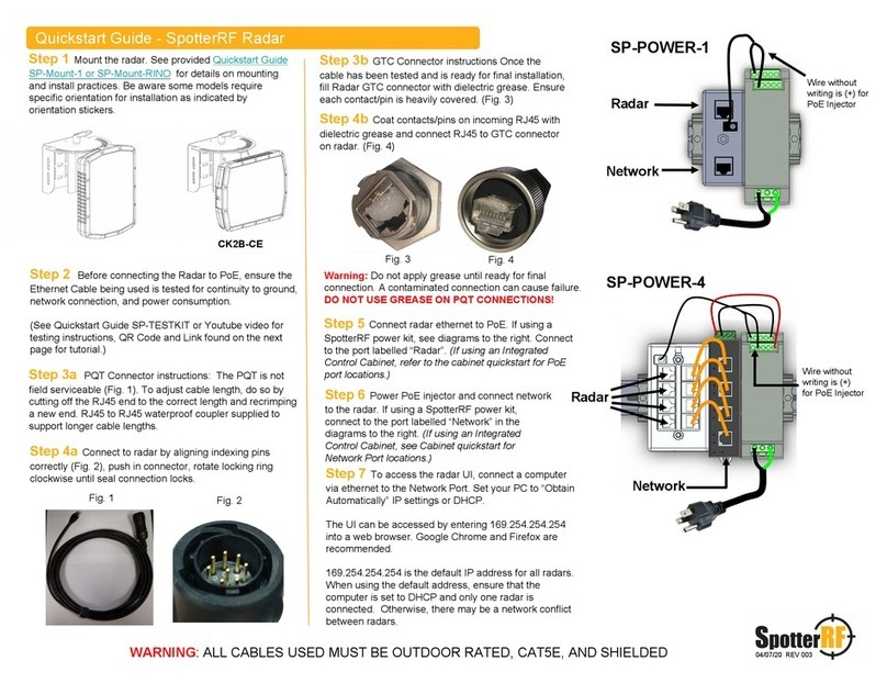
SpotterRF
SpotterRF CK2B-CE quick start guide
Garmin
Garmin VARIA ERTL616 owner's manual
Endress+Hauser
Endress+Hauser Micropilot FMR56 Brief operating instructions

Brigade
Brigade Backsense BS-9100 Installation & operating guide

Endress+Hauser
Endress+Hauser Micropilot FMR51 operating instructions

SpotterRF
SpotterRF 3D-500 quick start guide
Dahua
Dahua B240 quick start guide
Pulsar
Pulsar mmWAVE installation guide
Endress+Hauser
Endress+Hauser Levelflex FMP51 Brief operating instructions
