HIK VISION DS-TDSB00-EMM User manual

Traffic Flow Monitoring Radar
User Manual

Traffic Flow Monitoring Radar User Manual
i
About this Document
●This Document includes instructions for using and managing the Product. Pictures,
charts, images and all other information hereinafter are for description and
explanation only.
●The information contained in the Document is subject to change, without notice,
due to firmware updates or other reasons. Please find the latest version of the
Document at the Hikvision website (https://www.hikvision.com). Unless
otherwise agreed, Hangzhou Hikvision Digital Technology Co., Ltd. or its affiliates
(hereinafter referred to as "Hikvision") makes no warranties, express or implied.
●Please use the Document with the guidance and assistance of professionals
trained in supporting the Product. m2
About this Product
●This product can only enjoy the after-sales service support in the country or region
where the purchase is made.
●If the product you choose is a video product, please scan the following QR code to
obtain the "Initiatives on the Use of Video Products", and read it carefully.
Acknowledgment of Intellectual Property Rights
●Hikvision owns the copyrights and/or patents related to the technology embodied
in the Products described in this Document, which may include licenses obtained
from third parties.
●Any part of the Document, including text, pictures, graphics, etc., belongs to
Hikvision. No part of this Document may be excerpted, copied, translated, or
modified in whole or in part by any means without written permission.
●and other Hikvision’s trademarks and logos are the properties
of Hikvision in various jurisdictions.
●Other trademarks and logos mentioned are the properties of their respective
owners.
LEGAL DISCLAIMER
●TO THE MAXIMUM EXTENT PERMITTED BY APPLICABLE LAW, THIS DOCUMENT

Traffic Flow Monitoring Radar User Manual
ii
AND THE PRODUCT DESCRIBED, WITH ITS HARDWARE, SOFTWARE AND
FIRMWARE, ARE PROVIDED "AS IS" AND "WITH ALL FAULTS AND ERRORS".
HIKVISION MAKES NO WARRANTIES, EXPRESS OR IMPLIED, INCLUDING WITHOUT
LIMITATION, MERCHANTABILITY, SATISFACTORY QUALITY, OR FITNESS FOR A
PARTICULAR PURPOSE. THE USE OF THE PRODUCT BY YOU IS AT YOUR OWN RISK.
IN NO EVENT WILL HIKVISION BE LIABLE TO YOU FOR ANY SPECIAL,
CONSEQUENTIAL, INCIDENTAL, OR INDIRECT DAMAGES, INCLUDING, AMONG
OTHERS, DAMAGES FOR LOSS OF BUSINESS PROFITS, BUSINESS INTERRUPTION,
OR LOSS OF DATA, CORRUPTION OF SYSTEMS, OR LOSS OF DOCUMENTATION,
WHETHER BASED ON BREACH OF CONTRACT, TORT (INCLUDING NEGLIGENCE),
PRODUCT LIABILITY, OR OTHERWISE, IN CONNECTION WITH THE USE OF THE
PRODUCT, EVEN IF HIKVISION HAS BEEN ADVISED OF THE POSSIBILITY OF SUCH
DAMAGES OR LOSS.
●YOU ACKNOWLEDGE THAT THE NATURE OF THE INTERNET PROVIDES FOR
INHERENT SECURITY RISKS, AND HIKVISION SHALL NOT TAKE ANY
RESPONSIBILITIES FOR ABNORMAL OPERATION, PRIVACY LEAKAGE OR OTHER
DAMAGES RESULTING FROM CYBER-ATTACK, HACKER ATTACK, VIRUS INFECTION,
OR OTHER INTERNET SECURITY RISKS; HOWEVER, HIKVISION WILL PROVIDE
TIMELY TECHNICAL SUPPORT IF REQUIRED.
●YOU AGREE TO USE THIS PRODUCT IN COMPLIANCE WITH ALL APPLICABLE LAWS,
AND YOU ARE SOLELY RESPONSIBLE FOR ENSURING THAT YOUR USE CONFORMS
TO THE APPLICABLE LAW. ESPECIALLY, YOU ARE RESPONSIBLE, FOR USING THIS
PRODUCT IN A MANNER THAT DOES NOT INFRINGE ON THE RIGHTS OF THIRD
PARTIES, INCLUDING WITHOUT LIMITATION, RIGHTS OF PUBLICITY, INTELLECTUAL
PROPERTY RIGHTS, OR DATA PROTECTION AND OTHER PRIVACY RIGHTS. YOU
SHALL NOT USE THIS PRODUCT FOR ANY PROHIBITED END-USES, INCLUDING THE
DEVELOPMENT OR PRODUCTION OF WEAPONS OF MASS DESTRUCTION, THE
DEVELOPMENT OR PRODUCTION OF CHEMICAL OR BIOLOGICAL WEAPONS, ANY
ACTIVITIES IN THE CONTEXT RELATED TO ANY NUCLEAR EXPLOSIVE OR UNSAFE
NUCLEAR FUEL-CYCLE, OR IN SUPPORT OF HUMAN RIGHTS ABUSES.
●IN THE EVENT OF ANY CONFLICTS BETWEEN THIS DOCUMENT AND THE
APPLICABLE LAW, THE LATTER PREVAILS.
© Hangzhou Hikvision Digital Technology Co., Ltd. All rights reserved.
Symbol Conventions
The symbols that may be found in this document are defined as follows.
Traffic Flow Monitoring Radar User Manual
iii
Symbol
Description
Provides additional information to emphasize or supplement
important points of the main text.
Indicates a potentially hazardous situation, which if not avoided,
could result in equipment damage, data loss, performance
degradation, or unexpected results.
Indicates a hazard with a high level of risk, which if not avoided,
will result in death or serious injury.

Traffic Flow Monitoring Radar User Manual
iv
Table of Contents
Chapter 1 Product Introduction....................................................................................1
1.1 Shape................................................................................................................1
1.2 Port Introduction .............................................................................................1
Chapter 2 Debugging Software.....................................................................................4
2.1 Overview..........................................................................................................4
2.2 Installation Instruction....................................................................................4
2.3 Install Software ...............................................................................................4
2.4 Software Function Introduction .....................................................................4
2.4.1 Function Bar Area.................................................................................5
2.4.2 Information Display Area.....................................................................9
2.4.3 Radar Status Area...............................................................................10
2.4.4 Radar Parameter Setting Area...........................................................10
Chapter 3 FAQ..............................................................................................................15
3.1 Failed to connect to the radar. .....................................................................15
3.2 No vehicle target displayed after debugging. ..............................................15
3.3 Firmware upgrade operation description ....................................................15

Traffic Flow Monitoring Radar User Manual
1
Chapter 1 Product Introduction
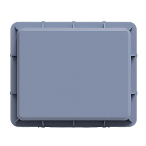
1.1 Shape
1.2 Port Introduction
Cable Color
Name
Cable Color
Name
Red
DC 24+
Green
RS-485+
Black
DC 24-
Blue
RS-485-
Brown
GND
Data communicates with other devices via Ethernet.

Traffic Flow Monitoring Radar User Manual
2
Chapter 2 Installation
The radar is recommended to be installed on the 6-meter high gantry, L-shaped rod,
column, etc., and formal installation is recommended. If it cannot be installed at the
positions above, the road side installation can also be considered. When installing on
the road side, you need to adjust the horizontal detection angle.
There should be no big blocking items in front of the radar, such as road sign, metal
mesh, advertising board, etc. The radar performance may be degraded because of the
blocking radar beams.
Installation:
Fix the radar and its bracket at the designated firm position of the pillar arm. The radar
installation should be oriented towards the detection area. It requires to tilt down 1
to 2 degrees when installing radar.
Figure 1 Installation

Traffic Flow Monitoring Radar User Manual
3
The radar should be fixed firmly on the bracket, and the material of the
bracket should be strong and durable enough to prevent vibration in case of
degrading the performance.
Ladders or aerial ladder truck shall be used during installation. The operation
shall follow the safety operation requirements. The worker should be
familiar with the power equipment, radar device operation and can work at
the high altitude.
When working at the heavy traffic road, the workers should wear safety
reflective jackets, safety helmets, and set warning signs as the safety
requirements asked.
The radar supply voltage is 24 VDC. It will cause damage when connecting to
220 VAC power, and the manufacturer doesn’t have any responsibility for
such operation.
If there is any damage about the cable when opening the package, please
stop the installation and DO NOT try to repair it by yourself. Please contact
the seller and confirm the damage with them.
Installation operation should comply with company safety regulations or
local safety policies.

Traffic Flow Monitoring Radar User Manual
4
Chapter 2 Debugging Software
2.1 Overview
This software is a debugging software for traffic flow monitoring radar. It is used to
set radar parameters, debug the radar, and troubleshooting.
2.2 Installation Instruction
Software: This software is suitable for running under Windows 7 system and above.
NET FrameWork4.0 or later (included in the installation package) and Windows 7 64-
bit version is recommended.
Hardware: The minimum configuration, 2.0 GHz CPU frequency, 2 GB memory, and 1
GB video memory. Independent graphics card is recommended for better display
effect.
2.3 Install Software
Run the setup.exe. If the computer does not installed with NET Framework, the
software will install NET Framework first. Then install the debug software by following
the installation wizard. After selecting the installation path, the wizard will install the
software automatically.
Click "finish" when the installation is completed. The software will create a shortcut
named "FCWRadarTestingSoftware. exe" on the desktop. Double click it, and run the
software.
2.4 Software Function Introduction
Fix the radar and turn it on. Connect the PC via Ethernet. Open the debugging software.
The initial interface is shown as Figure 2. The software interface is divided into the
software function bar area, radar parameter setting area, information display area,
and radar status area.
Click “connect”, and then input IP address of the radar. The default IP address is
203.0.113.64. The PC should be in the same network segment with that of the radar.
Set port (5000 and 9001 respectively as shown in Figure 3), and click OK.

Traffic Flow Monitoring Radar User Manual
5
Figure 2 Debugging Software
Figure 3 Connection Settings Menu
2.4.1 Function Bar Area
Figure 4 Function Bar Area
The function bar is divided into five parts: Main Menu, Road Information Setting,
Display interface Setting, Traffic Setting, and Data Playback Setting.
2.4.1.1 Main Menu Bar

Traffic Flow Monitoring Radar User Manual
6
Device connection: The radar communicates with the debugging software
through the Ethernet port. Click device connection, set the target IP address, click
OK, and wait for the device connection.
Disconnect the device: Disconnect the communication connection between the
host computer and the radar.
Product serial No. and software version: Information such as radar SN (product
serial No.) and software version can be viewed at the bottom of the interface.
Debugging mode: The gray icon indicates that the radar is in debugging mode. In
this status, the radar displays all targets detected within the entire beam range.
Normal mode: The gray icon indicates that the radar is in normal mode.
ID setting: When two or more radars are set up in the same direction or in the
same area, if the last digit of product SN is same, it shall be changed to a different
digit to avoid the interference.
Track trailing: Track trailing can realize the linearization of target motion
trajectory. By changing this value, the length of track trailing displayed by the
target can be changed.
Road length: Appropriate lane length can be defined according to the actual road
environment requirements, and the maximum length can be set up to 1200
meters.
Display trajectory: After the radar detects the vehicle target, it can track the
vehicle target sustainably and effectively until the target is out of the radar
detection range. Track display can observe the vehicle in the lane more intuitively.
If this option is selected, the target motion trajectory will be displayed. If this
option is not selected, it will not be displayed.
Clear track: When there are more targets detected, more tracks displayed on the
debugging software interface will affect the tester's judgment of vehicle motion.
At this time, the current trajectory can be cleared and only the vehicle driving
situation can be observed.
Vehicle type: Large, medium, and small vehicle types. Default status: ON.

Traffic Flow Monitoring Radar User Manual
7
Road information: Click and the road information dialog box appears, showing
the road queue length.
Vehicles number statistics: Click the number of vehicles statistics, you can display
and count the number of vehicles in each lane.
Enable/Disable channelization setting: Enable road channelization setting, which
is used to set road channelization at intersections.
Channelized road information display: Channelized setting on state. Click this
button to display or hide the channelized setting data.
Data preservation: This function can save the vehicle data information monitored
by the radar in real time, so that the user can read back the data, and provide the
user with an effective basis for the smooth operation of the road. If yes, the
playback data will be saved for later selection. In addition, if the camera is enabled,
the debugging software will hover over the interface of the camera to save
playback pictures, but the local camera does not need to do this operation.
Figure 5 Playback Data Prompt
Stop recording: This function can stop recording data. Click and you will be
reminded the path where the data is saved.
Network parameters setting: After you click Open, you need to enter the
password to change the network parameters. The password is 123++321. After
the change is successful, radar connection needs to be made with a new IP
address. (The new network parameters take effect only after the radar is restarted
after the network parameters are modified.)

Traffic Flow Monitoring Radar User Manual
8
Figure 6 Network Parameters Setting
Restore Default Settings: The radar parameters are restored to the default
settings.
Program upgrade: Update radar program via Ethernet port.
Radar restart: The radar can be restarted.
2.4.1.2 Road Information Setting Bar
You can set the number of lanes, vehicle driving direction, and other parameters, as
shown in the figure below:
Figure 7 Road Information Setting Bar
On this interface, you can set road main information, road median strip, road width,
and road direction. After setting, click “Set” to confirm the setting.
2.4.1.3 Display Interface Setting Bar
You can set the display effect of radar beam and lane, as shown below.
Figure 8 Display Interface Setting Bar
Add lines: You can add curvature or cross lane lines according to the real road
conditions by using the mouse to click 2 points on the position in the software.

Traffic Flow Monitoring Radar User Manual
9
Delete lines: You can delete extra lane lines according to the real road conditions.
You can operate by the mouse to click 2 points at the position.
Reset: Restore the lane lines displayed initially.
Add median strip: You can add median strip according to the real road by the
mouse to click 4 points in the desired position.
Remove median strip: According to the real road to clear the median strip settings
by the mouse to click 4 points in the desired position.
Reset median strip: Restore the initial setting of the median strip.
2.4.1.4 Traffic Setting bar
You can open and close the virtual coil function, and make statistics on road vehicles
as shown in the figure below.
Figure 9 Traffic Setting bar
Click "Turn On Virtual Loop Detector Setting Interface" button to turn on the virtual
loop detector setting interface (set loop detector type, coordinates, length and other
information). The “Receive information" bar automatically switches to the traffic
information interface. Set cycle time (unit: s), and click "Start Statistics" for road traffic
statistics.
2.4.1.5 Data Playback Settings Bar
You can realize the saved data playback function, as shown in the following figure.
Figure 10 Data Playback Settings Bar
This bar is used when the radar is disconnected. File is selected in folder which name
is the date instead of the PlayBackData folder. For example:
D:\\Data\\20210521-180603\\PlayBackData. You just need to choose folder
20210521-180603 instead of sub-folder PlayBackData.
2.4.2 Information Display Area

Traffic Flow Monitoring Radar User Manual
10
Figure 11 Information Display Window
Information Display Window can help user to record and observe the driving
conditions and information of target vehicles in real time. The display window mainly
includes target information, camera, road information, flow information, and road
condition model.
The target information window displays the information of the target vehicle detected
by the radar in real time, including the vehicle number, distance, lateral distance,
speed, lane number, and event information, which can help user to analyze real-time
monitoring data.
Camera connects to mainstream USB cameras and Hikvision cameras. After the
Camera is successfully connected, the user can cooperate with the lane 2D/3D model
according to the real-time video picture to help the user set up and debug the radar.
2.4.3 Radar Status Area
This area is located below the debugging software interface, and user can check the
radar connection status, product SN, software version, and other information in the
"radar status area".
2.4.4 Radar Parameter Setting Area
Radar debugging includes Common Settings, Advanced Settings, and Event Settings,
as shown below.

Traffic Flow Monitoring Radar User Manual
11
Figure 12 Parameter Setting Area
2.4.4.1 Common Setting
The user can set the radar scene type, installation parameters, sensitivity, and vehicle
type classification according to the real installation environment of the radar.
2.4.4.1.1 Scene Setting
You can choose main road type and intersection type.
Section: Usually does not include a road intersection.
High Speed:Select this mode when the radar is operating at high speed.
Intersection mode 1: Applicable to intersections with non-motor vehicle.
Intersection mode 2: Applicable to the intersection without non-motor vehicle.
Holographic intersection: It is suitable for the target monitoring under the
intersection.
2.4.4.1.2 Installation Setting
In this option, the user can set the installation height, horizontal offset, angle
correction, lower limit of blind area, Y-distance correction, stop target, and other
information according to the real installation environment of the radar.

Traffic Flow Monitoring Radar User Manual
12
Erection Height: The vertical height of the radar center from the ground.
Horizontal Offset: Correct the X-position offset of the radar with respect to the
center of the total road width. “-” to the left and “+” to the right.
Angular Correction: The adjustment range is ±12°, and correct lateral angle
deviation caused by radar installation angle deviation same as the horizontal
deviation correction. Left is “-” and right is “+”.
Stop line Distance: Set the radar's straight-line distance from the stop line.
Longitudinal distance correction: Correct the target distance error in Y direction.
Stop the target: Set the retention time of the stop target. The unit is second. If
the value is 0, the stop target will remain until it starts to move.
Two dimensional sensitivity: The ability of the radar to recognize the target
velocity. The higher the value, the lower the sensitivity, and the lower the target
detection rate. On the contrary, the smaller the value, the higher the sensitivity,
the higher the target detection rate, and the increase of false alarm. The user can
set it reasonably according to the real road conditions, and the recommended
value of sensitivity is 4.
One dimensional sensitivity: The ability of the radar to recognize the target
distance. The higher the value, the lower the sensitivity, and the lower the target
detection rate. On the contrary, the smaller the value, the higher the sensitivity,
the higher the target detection rate, and the increase of false alarm. The user can
set it reasonably according to the real road conditions, and the recommended
value of sensitivity is 4.
2.4.4.1.3 Vehicle Type Resolution:
Non-motor vehicle Come, Non-motor vehicle Go, Non-motor vehicle Limit Come,
Non-motor vehicle Limit Go:
The values of these four parameters are set as the sensitivity threshold. The smaller
the value, the greater the possibility of identification as a non-motor vehicle, and the
larger the value, the greater the possibility of identification as a non-motor vehicle.
Middle vehicle come, Large vehicle come,Middle vehicle go, Large vehicle go:

Traffic Flow Monitoring Radar User Manual
13
The values of the four parameters are set to the length of the vehicle in meters as
shown in Figure 13. It means that a motor vehicle larger than 6 meters and smaller
than 9 meters is judged as a middle vehicle, while a motor vehicle larger than 9 meters
is judged as a large vehicle.
Figure 13 Vehicle Length
2.4.4.2 Advanced Setting Bar
This window is mainly used for automatic angle correction of radar in debugging mode
and advanced sensitivity setting in special scenes.
By observing the CFAR point in the circular chart of the point cloud, it can determine
whether there is interference source in the radar beam range. If there is no target in
the field of vision, but there are more CFAR points concentrated all the time, it can be
adjusted by the "sensitivity setting" of 4 different distance ranges in the "advanced
sensitivity setting".
If the target trajectory is inconsistent with the real trajectory, click the "Automatic
Angle Correction" button to correct the angle to make them match with each other.
After debugging the radar, click the button of "Common Settings" on the left of
"Advanced Settings" to return to the standard interface, and then click the button of
"Normal Mode" to switch the radar to the normal working state.
2.4.4.3 Event Setting
In this window, you can set parameters such as High Speed Threshold, Slow Speed
Threshold, and Queue Length Event.
At present, the event detection supported by the radar includes regular parking,
congestion parking, vehicle overspeed, slow vehicle, opposite direction, etc. The event
detection results are displayed in the “event detection -- target information”in the
information display area.
The queue length and information of different lanes can be selected by setting the
queue length upper limit of the corresponding lane in Queue Length event.

Traffic Flow Monitoring Radar User Manual
14
Figure 14 Event Setting

Traffic Flow Monitoring Radar User Manual
15
Chapter 3 FAQ
3.1 Failed to connect to the radar.
Check whether the IP addresses of PC and radar are in same network segment.
Check status of power supply and the operating status of radar device.
Check the cable connection of radar is reliable or not.
3.2 No vehicle target displayed after debugging.
Check whether CFAR information in point cloud chart is good in “Advanced Setting
- Status Bar”.
Check radar parameters. Adjust radar elevation angle and horizontal offset to
make radar beam cover the target road lane.
Check the radar working status. Check whether the value of received bytes and
frames are changed in “Radar Status Bar” of the debugging software.
3.3 Firmware upgrade operation description
Before upgrading the radar firmware, disconnect the debugging software from
the radar. Click , the radar connection setting interface pops up. Enter the
radar IP address, and set the parameter port to 5000 by default (generally not
modified).
Figure 15 Radar Connection
Table of contents
Other HIK VISION Radar manuals

HIK VISION
HIK VISION DS-TDSB00-EKH User manual

HIK VISION
HIK VISION DS-TMG033 User manual

HIK VISION
HIK VISION DS-TMG035 User manual

HIK VISION
HIK VISION CSR-IM User manual

HIK VISION
HIK VISION DS-PR1-60 User manual

HIK VISION
HIK VISION DS-TD10N-1 User manual

HIK VISION
HIK VISION CSR-I Series User manual

HIK VISION
HIK VISION DS-TDSB0 Series User manual

HIK VISION
HIK VISION DS-TD10M-1 User manual

HIK VISION
HIK VISION DS-TDSB00-EKT User manual