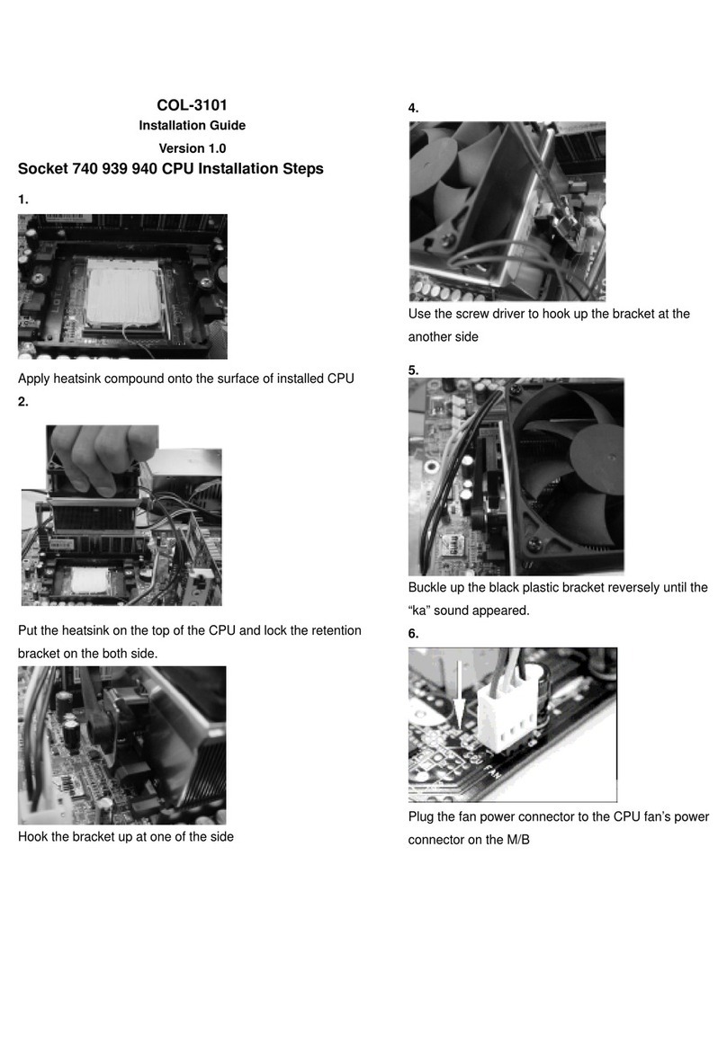
Senstar Stellar Sennet Perimitrax A3DA0102 User manual

Sennet®
Communications Network
Product
Guide
M0DA0302-001, Rev F
First edition
November 11, 2005

Senstar-Stellar locations
Canada
119 John Cavanaugh Drive
Carp, Ontario
Canada K0A 1L0
Telephone: +1 (613) 839-5572
Fax: +1 (613) 839-5830
Website: www.senstarstellar.com
Email: info@senstarstellar.com
See back cover for regional offices.
M0DA0302-001, Rev F, First edition
Perimitrax, Sennet, Senstar 100, Senstar-Stellar and the Senstar-Stellar logo are registered trademarks of Senstar-Stellar
Corporation. Intelli-FLEX is a trademark of Senstar-Stellar Corporation. Product names and Company names included in this
document are used only for identification purposes and are the property of, and may be trademarks of their respective owners.
Copyright © 2005, 2003, 2001,1999 Senstar-Stellar Corporation. All rights reserved. Printed in Canada.
The information provided in this guide has been prepared by Senstar-Stellar Corporation to the best of its ability. Senstar-Stellar
Corporation is not responsible for any damage or accidents that may occur due to errors or omissions in this guide. Senstar-
Stellar Corporation is not liable for any damages, or incidental consequences, arising from the use of, or the inability to use, the
software and equipment described in this guide. Senstar-Stellar Corporation is not responsible for any damage or accidents that
may occur due to information about items of equipment or components manufactured by other companies. Features and
specifications are subject to change without notice. Any changes or modifications to the software or equipment that are not
expressly approved by Senstar-Stellar Corporation void the manufacturer’s warranty.
Approvals - standard Transponder Unit, repeaters and Network Controller
Canada: This Class B digital apparatus meets all requirements of the Canadian Interference -Causing Equipment Regulations.
Cet appareil numérique de la classe B respecte toutes les exigences du Règlement sur le matériel brouilleur du Canada.
USA: This device complies with part 15 of the FCC Rules. Operation is subject to the following two conditions: (1) This device may
not cause harmful interference, and (2) this device must accept any interference received, including any interference that may
cause undesired operation.
The use of shielded cables is required for compliance.
Any changes or modifications not expressly approved by Senstar-Stellar Corporation could void the user’s authority to operate the
equipment.
Note: This equipment has been tested and found to comply with the limits for a Class B digital device, pursuant to part 15 of the
FCC Rules. These limits are designed to provide reasonable protection against harmful interference in a residential
installation.This equipment generates, uses and can radiate radio frequency energy and, if not installed and used in accordance
with the instructions, may cause harmful interference to radio communications. However, there is no guarantee that interference
will not occur in a particular installation. If this equipment does cause harmful interference to radio or television reception, which
can be determined by turning off and on, the user is encouraged to try to correct the interference by one or more of the following
measures:
- Reorient or relocate the receiving antenna.
- Increase the separation distance between the equipment and the receiver.
- Connect the equipment into an outlet on a circuit different from that to which the receiver is connected.
- Consult the dealer or an experienced radio/TV technician for help.
Europe: This device conforms to the protection requirement of council directives 89/336/EEC and 73/23/EEC on the
approximation of the laws of member states relating to Electromagnetic compatibility and low voltage directive, as amended by
directive 93/68/EEC.
Senstar-Stellar Corporation’s Quality Management System is ISO 9001:2000 registered.
Approvals for the Large Transponder Unit and the Remote Display and Control Panel are pending.

Related publications
Perimitrax
®
Site planning guide (A3DA0102):
Describes Perimitrax system features, operation, components and applications. It
also provides information regarding the design, planning, and ordering of
Perimitrax systems.
Perimitrax
®
Installation guide (A3DA0202)
:
Provides instructions for installing the Perimitrax system and system components.
Perimitrax
®
System setup guide (A3DA0302)
:
Provides instructions for calibrating and maintaining Perimitrax systems.
Information on system, setup, testing, system reports, diagnostics and
troubleshooting is also found in this manual.
Intelli-FLEX™ product guide (Multiplex version) (C6DA0402):
Describes Intelli-FLEX multiplex version features, operation, components and
applications. It also provides instructions for planning, installing and setting up
an Intelli-FLEX multiplex version system.
Senstar
®
100 Site Creation Planning Guide (DA-030213):
This guide provides detailed instructions on gathering the site data and designing
the Senstar 100 database.

Using this guide
This guide provides all of the information necessary to layout, install and setup a
Sennet system.
Chapter 1 describes each of the Sennet system components; chapter 2 provides
network layout guidelines; the equipment setup and installation instructions are
contained in chapter 3; chapter 4 details the system powering up instructions;
and chapter 5 describes the operating features for using the remote display and
control panel.
The appendices contain forms to assist in configuring your system, equipment
specifications, troubleshooting guidelines, maintenance procedures, device
address settings and a listing of available equipment for the Sennet system.
Device configuration forms
Throughout this guide, references are made to the device configuration forms.
These forms indicate the correct card settings and connections for the site. They
should be kept with the relevant units for future reference (a storage pocket is
provided in the enclosure for this purpose). See
appendix a - Device
configuration forms.
Figures
The figures contained in this document are for illustration purposes only, they
may differ from the actual equipment.
Abbreviations
The following abbreviations are used throughout this guide:
•
AC - alternating current
•
DC - direct current
•
I/O - input/output
•
LCD - liquid crystal display
•
LED - light emitting diode
•
LTU - the Sennet large transponder unit
•
NC - the Sennet network controller
•
n.c. - normally closed
•
n.o. - normally open
•
RDCP - the Sennet remote display and control panel
•
RP3PC - the Sennet repeater, 3-port, copper model
•
RP2PC - the Sennet repeater, 2-port, copper model
•
RP2PF - the Sennet repeater, 2-port, copper/fiber optic model
•
TU - the Sennet standard transponder unit
•
UPS - uninterruptible power supply
•
VDU - video display unit

CU^^Ud`b_TeSdWeYTUd_S!
Table of contents
1
Overview Sennet components
What is Sennet
- - - - - - - - - - - - - - - - - - - - - - - - - - - - - - - - - - - - - - - - - - - - - - - - - - - - - - - - 1-1
Network controller
- - - - - - - - - - - - - - - - - - - - - - - - - - - - - - - - - - - - - - - - - - - - - - - - - - - - - 1-4
Transponder unit
- - - - - - - - - - - - - - - - - - - - - - - - - - - - - - - - - - - - - - - - - - - - - - - - - - - - - - 1-6
Remote display and control panel
- - - - - - - - - - - - - - - - - - - - - - - - - - - - - - - - - - - - - - - - - - 1-12
Repeater
- - - - - - - - - - - - - - - - - - - - - - - - - - - - - - - - - - - - - - - - - - - - - - - - - - - - - - - - - - -
1-13
Perimitrax
®
Sensor Module
- - - - - - - - - - - - - - - - - - - - - - - - - - - - - - - - - - - - - - - - - - - - - - 1-15
Intelli-FLEX™ Multiplex version processor
- - - - - - - - - - - - - - - - - - - - - - - - - - - - - - - - - - - - -
1-16
Fiber optic interface module
- - - - - - - - - - - - - - - - - - - - - - - - - - - - - - - - - - - - - - - - - - - - - - 1-17
Hardware mounting options
- - - - - - - - - - - - - - - - - - - - - - - - - - - - - - - - - - - - - - - - - - - - - - 1-18
2
Network configuration
Network layout guidelines
- - - - - - - - - - - - - - - - - - - - - - - - - - - - - - - - - - - - - - - - - - - - - - - - 2-1
Network wiring requirements
- - - - - - - - - - - - - - - - - - - - - - - - - - - - - - - - - - - - - - - - - - - - - - 2-4
Network controllers - network layout
- - - - - - - - - - - - - - - - - - - - - - - - - - - - - - - - - - - - - - - - 2-11
Transponder units - network layout
- - - - - - - - - - - - - - - - - - - - - - - - - - - - - - - - - - - - - - - - - 2-12
Remote display and control panels - network layout
- - - - - - - - - - - - - - - - - - - - - - - - - - - - - -
2-14
Repeaters - network layout
- - - - - - - - - - - - - - - - - - - - - - - - - - - - - - - - - - - - - - - - - - - - - - - 2-15
Power supplies
- - - - - - - - - - - - - - - - - - - - - - - - - - - - - - - - - - - - - - - - - - - - - - - - - - - - - - - 2-18
Site plan guidelines
- - - - - - - - - - - - - - - - - - - - - - - - - - - - - - - - - - - - - - - - - - - - - - - - - - - 2-18
3
Installation, setup and wiring
Outline of installation procedures
- - - - - - - - - - - - - - - - - - - - - - - - - - - - - - - - - - - - - - - - - - - 3-1
Installing an enclosure
- - - - - - - - - - - - - - - - - - - - - - - - - - - - - - - - - - - - - - - - - - - - - - - - - - - 3-4
Installing the fiber optic interface module
- - - - - - - - - - - - - - - - - - - - - - - - - - - - - - - - - - - - - -
3-6
Wiring power to the enclosure
- - - - - - - - - - - - - - - - - - - - - - - - - - - - - - - - - - - - - - - - - - - - - - 3-8
Network controller - settings
- - - - - - - - - - - - - - - - - - - - - - - - - - - - - - - - - - - - - - - - - - - - - - 3-14
Network controller - connecting to the host annunciator
- - - - - - - - - - - - - - - - - - - - - - - - - - - -
3-19
Network Controller - power connection
- - - - - - - - - - - - - - - - - - - - - - - - - - - - - - - - - - - - - - - 3-20
Transponder unit - settings
- - - - - - - - - - - - - - - - - - - - - - - - - - - - - - - - - - - - - - - - - - - - - - - 3-21
Transponder unit - connecting to external devices
- - - - - - - - - - - - - - - - - - - - - - - - - - - - - - - -
3-25
Transponder unit - power connection
- - - - - - - - - - - - - - - - - - - - - - - - - - - - - - - - - - - - - - - - 3-26
Repeater - settings
- - - - - - - - - - - - - - - - - - - - - - - - - - - - - - - - - - - - - - - - - - - - - - - - - - - - 3-27
Repeater - power connection
- - - - - - - - - - - - - - - - - - - - - - - - - - - - - - - - - - - - - - - - - - - - - - 3-29
Large transponder unit - installation
- - - - - - - - - - - - - - - - - - - - - - - - - - - - - - - - - - - - - - - - 3-30

dQR\U_VS_^dU^dc
d_S"CU^^Ud`b_TeSdWeYTU
Large transponder unit - processor card settings
- - - - - - - - - - - - - - - - - - - - - - - - - - - - - - - - 3-32
Large transponder unit - connecting to external devices
- - - - - - - - - - - - - - - - - - - - - - - - - - - -
3-34
Large transponder unit - power connection
- - - - - - - - - - - - - - - - - - - - - - - - - - - - - - - - - - - - 3-36
Remote display and control panel - installation
- - - - - - - - - - - - - - - - - - - - - - - - - - - - - - - - - - 3-37
Remote display and control panel - settings
- - - - - - - - - - - - - - - - - - - - - - - - - - - - - - - - - - - - 3-38
Remote display and control panel - power connection
- - - - - - - - - - - - - - - - - - - - - - - - - - - - - -
3-40
4
Powering up procedures
Network controller - fiber optic cable
- - - - - - - - - - - - - - - - - - - - - - - - - - - - - - - - - - - - - - - - - 4-2
Network controller - copper wire
- - - - - - - - - - - - - - - - - - - - - - - - - - - - - - - - - - - - - - - - - - - - 4-3
Large transponder unit
- - - - - - - - - - - - - - - - - - - - - - - - - - - - - - - - - - - - - - - - - - - - - - - - - -
4-4
Standard transponder unit - fiber optic cable
- - - - - - - - - - - - - - - - - - - - - - - - - - - - - - - - - - - - 4-5
Standard transponder unit - copper wire
- - - - - - - - - - - - - - - - - - - - - - - - - - - - - - - - - - - - - - - 4-6
Remote display and control panel
- - - - - - - - - - - - - - - - - - - - - - - - - - - - - - - - - - - - - - - - - - - 4-7
Repeaters
- - - - - - - - - - - - - - - - - - - - - - - - - - - - - - - - - - - - - - - - - - - - - - - - - - - - - - - - - - -
4-8
5
Processing alarms at the remote display and control panel
Control panel components
- - - - - - - - - - - - - - - - - - - - - - - - - - - - - - - - - - - - - - - - - - - - - - - - 5-1
Acknowledge alarms
- - - - - - - - - - - - - - - - - - - - - - - - - - - - - - - - - - - - - - - - - - - - - - - - - - - -
5-2
Disable Sensor
- - - - - - - - - - - - - - - - - - - - - - - - - - - - - - - - - - - - - - - - - - - - - - - - - - - - - - - -
5-2
Enable Sensor
- - - - - - - - - - - - - - - - - - - - - - - - - - - - - - - - - - - - - - - - - - - - - - - - - - - - - - - -
5-3
Viewing lists
- - - - - - - - - - - - - - - - - - - - - - - - - - - - - - - - - - - - - - - - - - - - - - - - - - - - - - - - -
5-3
Appendix - a
Device configuration forms
Appendix - b
Specifications
Appendix - c
Troubleshooting
Appendix - d
Maintenance procedures
Appendix - e
Device address settings
Appendix - f
Spare parts list
Appendix - g
Dual ported Network Controller
Appendix - h
M0KT0500 Repeater
Index

CU^^Ud`b_TeSdWeYTU!!
1Overview Sennet components
What is Sennet
Sennet
®
is Senstar-Stellar Corporation’s alarm communications network designed
specifically for security monitoring applications. Each Sennet network consists of
a network controller, and a combination of hardware components, (large
transponder units (LTU), transponder units (TU), remote display and control
panels (RDCP), Perimitrax
®
buried line sensor Sensor Modules, Intelli-FLEX™
fence sensor multiplex processors and repeaters), as required by the site.

GXQdYcCU^^Ud
!"CU^^Ud`b_TeSdWeYTU
The network provides fast, reliable and secure communications between your
security devices and a host alarm annunciator, such as Senstar-Stellar’s
Senstar
®
100 alarm annunciation system. The alarm annunciator allows you to
configure each network device individually to process specific maintenance,
setup and alarm information. The annunciator can also be configured to receive
information from intrusion sensors and other security devices, as well as send
messages to security devices; for example, to trigger a siren or unlock a door.
The intrusion sensors and security devices can be hundreds of metres or even
many kilometres from your annunciator. A network repeater circuit card is used
to expand the maximum distance of the network to enable this possibility. This is
especially useful when applied to outdoor security systems.
Each device in a Sennet network runs on its own power supply. Where possible,
provisions have been made for an optional backup battery. Where this is not
possible, an external AC UPS is recommended.
features
•
flexible
•
reliable data transmission
•
fast response time
•
easy installation and maintenance
•
expandable
BU\YQR\UTQdQdbQ^c]YccY_^
Sennet’s powerful data protocol and redundant hardware ensures that intrusions
are always reported.
•
Dual physical data paths increase reliability.
•
Powerful data error detection algorithms enable alarm messages to get
through even in the presence of noisy or intermittent data paths.
•
The source of each alarm message is verified. Any sabotage or tampering with
messages is detected and reported. Communication errors are reported and
tabulated in a maintenance report.
•
Physical tamper detection circuits are provided for all hardware enclosure.
6QcdbUc`_^cUdY]U
Sennet maximizes operator response by carrying alarm information between
security devices and the annunciator, typically in 100 ms. Network delay time is
never longer than 500 ms.

GXQdYcCU^^Ud
CU^^Ud`b_TeSdWeYTU!#
5QciY^cdQ\\QdY_^Q^T]QY^dU^Q^SU
Sennet is designed for simple installation and maintenance. Twisted-pair wiring or
multi-mode fiber optic cabling connects all devices with the network controller,
eliminating the need for complex wiring. Installation and replacing parts is fast
and easy with snap-in circuit boards, removable terminal blocks, and a minimum
number of circuit board switches. Battery charging circuitry is built in - adding
UPS capability is simply a matter of connecting a battery. Sennet provides built-in
diagnostics for help in troubleshooting and maintenance.
5h`Q^TQR\U
Sennet is flexible. Networks can be as small as one network controller and one
network transponder, located up to 1.2 km (¾ mile) apart. Transponders and
repeaters extend network length to 13 km (8 miles) and increase its capacity to
992 input points and 496 output points. A total network capacity of 3392 inputs,
2976 outputs can be achieved by connecting combinations of Sennet-compatible
devices - TUs, LTUs, RDCPs, etc. Multiple transponder networks can be used with
one annunciator.
Sennet’s data protocol was designed specifically to meet future security
requirements. In addition to the twisted-pair format, it supports communication
via optical fiber and coaxial cable (Perimitrax Sensor Module only). Built-in
redundancy and error handling are designed to adapt to the transmission
medium.
The Sennet network is being developed to support more devices in the future.

>Udg_b[S_^db_\\Ub
!$CU^^Ud`b_TeSdWeYTU
Network controller
The Sennet system must include a network controller in order to relay
information to and from the network.
The network controller acts as the traffic director for the network. It manages all
information which passes between the host annunciator and the network. One
annunciator may support several networks; contact your supplier for information.
Options for annunciation systems include the Senstar-Stellar Senstar
®100, the
Senstar-Stellar Perimitrax
®Central Controller, the Senstar-Stellar Intelli-FLEX™
Central Controller or a user supplied annunciator.
The network controller connects to the host annunciator(s) through the RS-232/
RS-422 serial port interface(s), and connects to the transponders through
redundant RS-485 copper wire, fiber optic or coaxial cable data paths. The coaxial
cable is compatible only with the Perimitrax Sensor Module.
The network controller monitors the devices, checks network integrity, and relays
alarm and diagnostic information to the host.
The network controller accepts 12 VDC, 16 VAC or 110-120/220-240 VAC power
input. The AC operation provides a charger to support local UPS operation with
an optional battery. The power supply and network controller are mounted on a
Sennet mounting plate which can then be mounted either in a secured area or in
an enclosure.

>Udg_b[S_^db_\\Ub
CU^^Ud`b_TeSdWeYTU!%
The supplied local UPS operation applies
only to the network controller. It does not
extend to the other network devices
features
•
two serial port RS-232 or RS-422 connections with RTS/CTS hardware
handshaking to the host alarm annunciator and control unit - jumper-
selectable
•
interface to the serial port - jumper-selectable
•
host annunciator baud rate - DIP-switch-selectable
•
network baud rate - jumper-selectable
•
network end-of-line termination circuits - jumper-selectable
•
quick connection to network - removable terminal blocks
•
timeout monitor enable/disable - jumper-selectable
•
AC fail alarm annunciation - DIP-switch-selectable
•
push-button Test and Reset switches
•
8 red LEDs - diagnostic status indicators
•
4 green LEDs - serial port activity indicators
•
2 green LEDs - network activity indicators
•
12 VDC, 16 VAC or 110-120/220-240 VAC power, optional battery backup
•
RS-485 copper wire or fiber optic cable compatible (through optional fiber
optic interface module)

DbQ^c`_^TUbe^Yd
!&CU^^Ud`b_TeSdWeYTU
Transponder unit
The transponder unit collects and translates data from distributed sources (e.g.,
fence-mounted sensors, infrared motion detectors, door and window contacts,
microwave sensors). Each transponder provides optional relay outputs that can
activate local devices (e.g., mimic panels, gate or door controls, sirens, lights).
Two types of transponder units are available for the Sennet network - the standard
transponder unit and the large transponder unit. The standard transponder unit
is best suited to collecting and distributing small clusters of security alarm points
that are not centrally located. The large transponder unit is more appropriate for
a large number of input/output (I/O) points that are concentrated in a specific
area.
cdQ^TQbTdbQ^c`_^TUbe^Yd
There are 2 versions of the standard transponder unit. One version has an I/O
point capacity of 16 inputs/8 outputs, the other version has a 16 input point
capacity, with no output point capacity. These units, capable of indoor or outdoor
operation, must be mounted in an enclosure or in a protected area.

DbQ^c`_^TUbe^Yd
CU^^Ud`b_TeSdWeYTU!'
Each transponder unit accepts 12 VDC, 16 VAC or 110-120/220-240 VAC power
input. The AC operation provides a charger to support local UPS operation with
an optional battery. The power supply and transponder unit are mounted on a
Sennet mounting plate which can then be mounted either in a secured area or in
an enclosure.
The supplied local UPS operation applies
only to the transponder unit. It does not
extend to the other network devices
features - standard transponder unit
•
network device address - DIP-switch-selectable
•
network baud rate - jumper-selectable
•
network end-of-line termination circuits - jumper-selectable
•
quick connection to network inputs/outputs - removable terminal blocks
•
timeout monitor enable/disable - jumper-selectable
•
push-button Test and Reset switches
•
16 red LEDs - input alarm/tamper and diagnostic status indicators
•
8 red LEDs - optional output relay activity indicators
•
2 green LEDs - network activity indicators
•
16 supervised inputs
•
8 dry-contact outputs (optional)
•
output type (normally open - n.o., normally closed - n.c.) - jumper-selectable
•
12 VDC, 16 VAC or 110-120/220-240 VAC power, optional backup battery
\QbWUdbQ^c`_^TUbe^Yd

DbQ^c`_^TUbe^Yd
!(CU^^Ud`b_TeSdWeYTU
The half-chassis version of the LTU has an I/O capacity of 128 inputs and 128
outputs. Each unit consists of a 19-inch rack mount half-chassis that contains a
processor card, the power supply for the LTU and slots for two I/O cards.
A full chassis version of the large transponder unit (LTU) is also available. This
unit has an I/O capacity of 256 inputs and 256 outputs. Each unit consists of a
19-inch rack mount chassis that contains a processor card, the power supply for
the LTU and slots for four I/O cards.
Each I/O card faceplate provides two input connector ports (J1 and J2) and three
output connector ports (J3, J4 and J5). The 64 supervised input structure is
identical for each of the 3 card types, however, the output structure is different for
each - 64 relay, 32 relay and 64 lamp driver. These are described more fully in the
sections that follow.
The processor card faceplate houses the connectors to the X and Y Sennet
network connections (TB1 and TB2 respectively).
The 115/230 VAC LTU power supply, mounted inside the rear of the LTU chassis,
provides power to the processor card and the LTU I/O circuit cards.
The power and voltage selection switches are mounted on the rear wall of the
LTU chassis above the power supply.
1/2-height chassis shown

DbQ^c`_^TUbe^Yd
CU^^Ud`b_TeSdWeYTU!)
features
•
network device address - DIP-switch-selectable
•
network baud rate - jumper-selectable
•
network end-of-line termination circuits - jumper-selectable
•
quick connection to network inputs/outputs - removable terminal blocks
•
2 green LEDs - network activity indicators
•
timeout monitor enable/disable - jumper-selectable
•
2 red LEDs - power and reset status indicators
•
256 supervised inputs (maximum) in blocks of 64
•
256 outputs (maximum) in blocks of 64
•
19-inch rack chassis
•
wall or rack mount
•
1/2-height chassis accommodates 2 I/O cards
•
full height chassis accommodates 4 I/O cards
•
115/230 VAC power supply
LTU processor card
The LTU processor card slides into the lower slot position in both the ½ and full
LTU chassis. Network settings and connections, and power and communication
connections to the I/O cards are made at the LTU processor card.

DbQ^c`_^TUbe^Yd
!! CU^^Ud`b_TeSdWeYTU
Output relay cards
The 64 output relay card contains the circuitry required to connect 64 supervised
inputs and 64 relay outputs to the network. Jumper settings for n.o. and n.c. relay
configurations are made on this card. The back of the card provides connectors
for power and communication from the processor card. The faceplate houses 2
input and 3 output ports.
The 32 output relay card is similar to the 64 output card with the exception that
only 32 outputs are available.
Both of these cards are mounted above the processor card in the ½ or full LTU
chassis.

DbQ^c`_^TUbe^Yd
CU^^Ud`b_TeSdWeYTU!!!
Output lamp driver card
The output lamp driver contains the circuitry necessary to connect 64 supervised
inputs and to activate 64 output lamps. The back of the card provides connectors
for power and communication from the LTU. The faceplate houses 2 input and 3
output ports.
This card is mounted above the processor card in the ½ or full LTU chassis.

BU]_dUTYc`\QiQ^TS_^db_\`Q^U\
!!"CU^^Ud`b_TeSdWeYTU
Remote display and control panel
The remote display and control panel (RDCP) enables the system to display and
process alarms at a location that is different from the central annunciation system.
The unit can be mounted in a 19-inch rack, in a wall or on a table top. Each
Sennet network can accommodate 16 of these panels based on Senstar 100
specifications.
The RDCP accepts 12 VDC or 16 VAC power input. The customer-supplied power
supply should be mounted close to the panel in a secure location.
circuit card features
•
network device address - DIP-switch-selectable
•
network baud rate - jumper-selectable
•
network end-of-line termination circuits - jumper-selectable
•
quick connection to network inputs/outputs - removable terminal blocks
•
timeout monitor enable/disable - jumper-selectable
•
2 green LEDs - network activity indicators
•
adjustable LCD contrast
•
adjustable LED backlight intensity
•
adjustable audible alarm
•
255 alarm points (maximum)
•
input power connector
•
12 VDC/16 VAC power supply

BU`UQdUb
CU^^Ud`b_TeSdWeYTU!!#
faceplate features
•
4 line by 40 character backlit LCD
•
6 control keys
•
volume control
•
LED alarm activity indicator
Repeater
Three repeater card options are available for the Sennet network. A 2- or 3-port
option is available for copper wire network applications. A 2-port copper/fiber
optic option is also available. This repeater is used for networks that use fiber
optic cabling exclusively and also in networks where copper wire and fiber optic
cabling are both used. In the latter instance, the copper/fiber optic repeater can
be used to translate data signals between copper wire and fiber optic cable
compatible signals.
For copper wire networks, repeaters are required to extend the operational
distance between network devices beyond the 1.2 km (¾ mile) limit (or the
specified number of devices allowed), or to implement nonlinear configurations
such as branches or stars.
The fiber optic option may be used in networks where lightning may be a
concern, such as an outdoor application, or in cases where the distance between
2 network devices is beyond the 1.2 km limit for the copper wire, but within the 2
km (1¼ mile) range of the fiber optic cabling.
The repeater is mounted on a Sennet mounting plate which can then be mounted
either in a secured area or in an enclosure.

BU`UQdUb
!!$CU^^Ud`b_TeSdWeYTU
The repeater accepts 12 VDC, 16 VAC or 110-120/220-240 VAC power input. The
AC operation provides a charger to support local UPS operation with an optional
battery. The power supply and repeater are mounted on a Sennet mounting plate
which can then be mounted either in a secured area or in an enclosure.
The supplied local UPS operation applies
only to the repeater. It does not extend to
the other network devices.
features
•
operation independent of network baud rate
•
network end-of-line termination circuits - jumper-selectable
•
quick connection to network - removable terminal blocks
•
2 green LEDs - communications status indicators
•
AC fail and tamper switch output connections used as inputs to a nearby
transponder
•
2 red LEDs - AC and DC power status indicators
•
1 red LED - communication failure indicator
•
on-board network transient protection
•
12 VDC, 16 VAC or 110-120/220-240 VAC power, optional backup battery
•
compatible with 50/125, 62.5/125 and 100/140 multimode fiber optic cable
This manual suits for next models
4
Table of contents
Popular Computer Hardware manuals by other brands
Cypress Semiconductor
Cypress Semiconductor STK14C88-5 Specification sheet

Galaxy
Galaxy GHDX2-2430S-24F4D Installation and hardware reference manual
zapco
zapco DSP-Z8 IV II owner's manual
Cypress Semiconductor
Cypress Semiconductor CY7C1543V18 Specification sheet
TJ Media
TJ Media TEF- user manual

Lake
Lake LM Series quick start guide

