IBT Technologies ET863i User manual

ET863i
Intel Pentium III =PN133T
ETX CPU Module
USER’S MANUAL
Version 1.0
.

ii ET863 User’s Manual
Acknowledgments
Award is a registered trademark of Award Software International,
Inc.
PS/2 is a trademark of International Business Machines
Corporation.
Microsoft Windows is a registered trademark of Microsoft
Corporation.
All other product names or trademarks are properties of their
respective owners.

ET863i User’s Manual iii
Table of Contents
Introduction.....................................................................1
Product Description ........................................................1
Checklist........................................................................2
Specifications .................................................................3
Dimensions.....................................................................4
Connector Locations on ET863i.......................................5
BIOS Setup.....................................................................11
Drivers Installation.......................................................33
VIA 4 in 1 Drivers Installation.......................................34
VGA Drivers Installation...............................................39
LAN Drivers Installation...............................................42
Audio Drivers Installation..............................................46
Appendix ........................................................................49
A. I/O Port Address Map..............................................49
B. Interrupt Request Lines (IRQ) ..................................50

iv ET863i User’s Manual
This page is intentionally left blank.

INTRODUCTION
ET863i User’s Manual 1
Introduction
Product Description
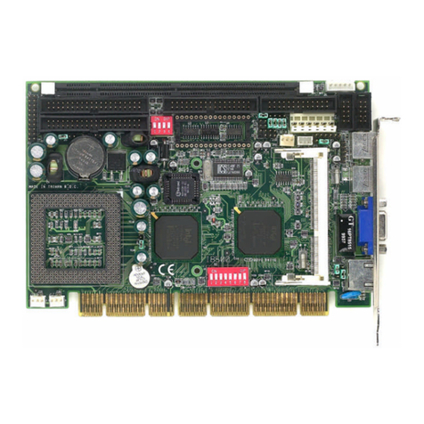
ET863i is an ETX CPU module with Intel Pentium III processors on board.
Using Intel's advanced 0.18-micron process technology, the onboard
mobile Intel Pentium III processor (500MHz) runs at a fixed speed and
offers lower power.
ETX stands for Embedded Technology extended, a technology or form
factor that offers flexible time-to-market solution, enabling product
development time to shrink from four months to just four weeks. It also
features low power consumption and low heat emission, eliminating the
need for a CPU fan.
System memory is provided by a SO-DIMM socket that supports up
512MB of SDRAM memory. The Award BIOS facilitates easy system
configuration and peripheral setup. Other advanced features of ET863i
includes:
On Board Savage AGP4X Graphics, LVDS
Realtek RTL8100BL LAN Controller
Built-in Audio with AC97 Codec, TV-out
4 USB port interface
TheET863ihasfourboard-to-boardhigh-densityinterfaceconnectorsfor
I/Osignalsthatplugontobaseboardsspecifictocustomer’sapplications.
ETX embedded solutions provide fast time-to-market through the
interchangeability and scalability of both the ETX module and the
baseboard.

INTRODUCTION
2ET863i User’s Manual
Checklist
Your ET863i package should include the items listed below.
•
The ET863i CPU Module
•
This User’s Manual
•
1 CD containing the following:
•
Chipset Drivers
•
Flash Memory Utility

INTRODUCTION
ET863i User’s Manual 3
Specifications
Product Name ET863i
Form Factor ETX
CPU Type Intel Mobile Pentium III 500Mhz or higher
CPU Voltage 1.05V~1.825V
CPU External
Clock 100Mhz
Chipset VIA Pro SavageTwisterT(PN133T)+VT82C686BChipset
North Bridge: VT8606 552 Pin PBGA
South Bridge: VT82C686A/B 352 Pin BGA
BIOS Award BIOS Support ACPI Function
Cache 128K/256K Level 2 Cache (CPU integrated)
On Board VGA VT8606 with Integrated Savage4 AGP4x Graphic
8/16/32 MB frame buffer using system memory
Integrated 2-channel 110MHZ LVDS interface
LAN Realtek RTL8100BL Single Chip Ethernet Controller
10/100 Base-T support
Sound VT82C686A/B Built-in Sound controller + AC97 Codec
VIA1611A (Line-out, Line-in, Mic.)
Memory Type 1x SODIMM 3.3V Max. 512MB
Support PC100/PC133 SO-DIMM Module
Super I/O VIA VT82C686A/B: IrDAx1 Parallel x1, COM1/2
(RS-232), FDC 2.88MB (3 Mode support), Hardware
monitor(2 thermal inputs,4 voltage monitor inputs, VID0-4
RTC/CMOS VT82C686A/B Built-in
Local Bus IDE VT82C686A/B Built-in, IDE1, IDE2
ETX Interface Connectors x 4
For PCI-bus, USB, Sound, VGA LCD, COM1, COM2,
LPT, Floppy, IrDA, Mouse, Keyboard, IDE1, IDE2,
Ethernet, ISA
USB Supports 4 ports, transfer rate up to 12Mb/s
Board Size 95mm x 114mm (3.74”x 4.5”)

INTRODUCTION
4ET863i User’s Manual
Dimensions
(Top View)

INTRODUCTION
ET863i User’s Manual 5
Connectors on ET863i
1. CN1 (ISA-Bus)........................................................................................6
2. CN2 (IDE 1, IDE 2, Ethernet, Misc)......................................................7
3. CN3 (PCI-Bus, USB, Sound).................................................................8
4. CN4 (VGA, LCD, Video, COM, COM2, LPT/Floppy, IrDA, Mouse,
Keyboard)....................................................................................................8
5. J2: FDD Connector.................................................................................9

INTRODUCTION
6ET863i User’s Manual
1. CN1 (ISA-Bus)
Pin Signal Pin Signal Pin Signal Pin Signal
1GND 2GND 51 VCC 52 VCC
3SD14 4SD15 53 SA6 54 IRQ5
5SD13 6MASTERJ 55 SA7 56 IR06
7SD12 8DREQ7 57 SA8 58 IRQ7
9SD11 10 DACKJ7 59 SA9 60 SYSCLK
11 SD10 12 DREQ6 61 SA10 62 REFSHJ
13 SD9 14 DACKJ6 63 SA11 64 DREQ1
15 SD8 16 DREQ5 65 SA12 66 DACKJ 1
17 MEMWJ 18 DACKJ5 67 GND 68 GND
19 MEMRJ 20 DREQ0 69 SA13 70 DREQ3
21 LA17 22 DACKJ0 71 SA14 72 DACKJ3
23 LA18 24 IRQ14 73 SA15 74 IORJ
25 LA19 26 IR015 75 SA16 76 IOWJ
27 LA20 28 IRQ12 77 SA18 78 SA17
29 LA21 30 IRQ11 79 SA19 80 SMEMRJ
31 LA22 32 IRQ10 81 IOCHRD
Y82 AEN
33 LA23 34 1016J 83 VCC 84 VCC
35 GND 36 GND 85 SD0 86 SMEMWJ
37 SBHEJ 38 M16J 87 SD2 88 SD1
39 SAO 40 OSC 89 SD3 90 NOWSJ
41 SA1 42 BALE 91 DREQ2 92 SD4
43 SA2 44 TC 93 SD5 94 IRQ9
45 SA3 46 DACKJ2 95 SD6 96 SD7
47 SA4 48 IR03 97 IOCHKJ 98 RSTDRV
49 SA5 50 IRQ4 99 GND 100 GND

INTRODUCTION
ET863i User’s Manual 7
2. CN2 (IDE 1, IDE 2, Ethernet, Misc)
Pin Signal Pin Signal Pin Signal Pin Signal
1GND 2GND 51 SIDE IOWJ 52 PIDE_IORJ
35V SB 4PWGIN 53 SIDE DRQ 54 PIDE IOWJ
5PS ON 6SPEAKER 55 SIDE D15 56 PIDE DRQ
7PWRBTNJ 8BATT 57 SIDE DO 58 PIDE D15
9KBINH 10 LILED 59 SIDE D14 60 PIDE DO
11 NC 12 ACTLED 61 SIDE D1 62 PIDE D14
13 NC 14 SPEEDLED 63 SIDE D13 64 PIDE D1
15 NC 16 NC 65 GND 66 GND
17 VCC 18 VCC 67 SIDE D2 68 PIDE D13
19 OVCRJ 20 GPCSJ 69 SIDE D12 70 PIDE D2
21 EXTSMI 22 NC 71 SIDE D3 72 PIDE D12
23 SMBCLK 24 SMBDATA 73 SIDE-D 1 74 PIDE D3
25 SIDE_CS3J 26 N.C. 75 SIDE D4 76 PIDE D11
27 SIDE CS1J 28 DASP S 77 SIDE D10 78 PIDE D4
29 SIDE A2 30 PIDE_CS3J 79 SIDE D5 80 PIDE D10
31 SIDE AO 32 PIDE CS1J 81 VCC 82 VCC
33 GND 34 GND 83 SIDE-D9 84 PIDE D5
35 NC 36 PIDE_A2 85 SIDE D6 86 PIDE D9
37 SIDE Al 38 PIDE_A0 87 SIDE-D8 88 PIDE D6
39 SIDE INTRO 40 PIDE A1 89 N.C. 90 N.C.
41 N.C. 42 N.C. 91 RXD- 92 PIDE D8
43 SIDE_AKJ 44 PIDE INTRO 93 RXD+ 94 SIDE D7
45 SIDE_RDY 46 PIDE_AKJ 95 TXD- 96 PIDE D7
47 SIDE_IORJ 48 PIDE RDY 97 TXD+ 98 HDRSTJ
49 VCC 50 VCC 99 GND 100 GND

INTRODUCTION
8ET863i User’s Manual
3. CN3 (PCI-Bus, USB, Sound)
Pin Signal Pin Signal Pin Signal Pin Signal
1GND 2GND 51 VCC 52 VCC
3PCICLK3 4PCICLK4 53 PAR 54 SERRJ
5GND 6GND 55 GPERRJ 56 N C
7PCICLK1 8PCICLK2 57 PMEJ 58 USB20
9REQJ3 10 GNTJ3 59 LOCKJ 60 DEVSELJ
11 GNTJ2 12 3V 61 TRDYJ 62 USB30
13 REQJ2 14 GNTJ1 63 IRDYJ 64 STOPJ
15 REQJ 1 16 3V 65 FRAMEJ 66 USB21
17 GNTJ0 18 N.C. 67 GND 68 GND
19 VCC 20 VCC 69 AD16 70 CBEJ2
21 SERIRQ 22 REQJ0 71 AD17 72 USB31
23 AD0 24 3V 73 AD19 74 AD18
25 AD1 26 AD2 75 AD20 76 USB00
27 AD4 28 AD3 77 AD22 78 AD21
29 AD6 30 AD5 79 AD23 80 USB10
31 CBFJ0 32 AD7 81 AD24 82 CBEJ3
33 AD8 34 AD9 83 VCC 84 VCC
35 GND 36 GND 85 AD25 86 AD26
37 AD10 38 AUXAL 87 AD28 88 USB01
39 AD11 40 MIC 89 AD27 90 AD29
41 AD12 42 AUXAR 91 AD30 92 USB11
43 AD13 44 ASVCC 93 PCIRSTJ 94 AD31
45 AD14 46 SNDL 95 IRQY 96 IRQZ
47 AD15 48 ASGND 97 IRQW 98 IRQX
49 CBEJ1 50 SNDR 99 GND 100 GND

INTRODUCTION
ET863i User’s Manual 9
4. CN4 (VGA, LCD, Video, COM, COM2, LPT/Floppy, IrDA,
Mouse, Keyboard)
Pin Signal Pin Signal Pin Signal Pin Signal
1GND 2GND 51 N C 52 N C
3R4B53 VCC 54 GND
5HSY 6G55 /STB 5 6 /AFD
7VSY 8DDCK 57 ic. 58 PD7
9NC 10 DDDA 59 IRRX 60 /ERR
11 TYCLK# 12 NC 61 IRTX 62 PD7
13 TYCLK 14 NC 63 RXD2 64 /INIT
15 GND 16 GND 65 GND 66 GND
17 TY1 18 TY2 67 RTS2J 68 PD5
19 TY1# 20 TY2# 69 DTR2J 70 /SLIN
21 GND 22 GND 71 DCD2J 72 PD4
23 NC 24 TY0 73 DSR2J 74 PD3
25 NC 26 TY0# 75 CTS2J 76 PD2
27 GND 28 GND 77 TXD2J 78 PD1
29 TX2# 30 TXCLK 79 RI2J 80 PD0
31 TX2 32 TXCLK# 81 VCC 82 VCC
33 GND 34 GND 83 RXD1 84 /ACK
35 TX0 36 TX1 85 RTS1J 86 /BUSY
37 TX0# 38 TX1# 87 DTR1J 88 PE
39 VCC 40 VCC 89 DCD1J 90 /SLCT
41 JILI_DAT 42 LTGIO0 91 DSR1J 92 MSCLK
43 JILi_CLK 44 BLON# 98 CTS1J 94 MSDAT
45 BIASON 46 DIGON 95 TXD1 96 KBCLK
47 COMP 48 Y97 RI1J 98 KBDAT
49 NC 50 C99 GND 100 GND
5. J2: FDD Connector
Pin Signal Pin Signal
1VCC 2INDEX
3VCC 4DRV_SEL
5VCC 6DSK_CH
7NC 8NC
9NC 10 MOTOR
11 DINST 12 DIR
13 NC 14 STEP
15 GND 16 WDATA
17 GND 18 EGATE
19 GND 20 TRACK
21 NC 22 WPROT
23 GND 24 RDATA
25 GND 26 SIDE
Note:JP1 and S1 are for manufacturing test use only.

INTRODUCTION
10 ET863i User’s Manual
This page is intentionally left blank.

BIOS SETUP
ET863i User’s Manual 11
BIOS Setup
This chapter describes the different settings available in the Award BIOS
that comes with the CPU card. The topics covered in this chapter are as follows:
BIOS Introduction.......................................................................12
BIOS Setup...................................................................................12
Standard CMOS Setup...............................................................14
Advanced BIOS Features ..........................................................17
Advanced Chipset Features......................................................20
Integrated Peripherals.................................................................23
Power Management Setup.........................................................25
PNP/PCI Configurations.............................................................28
PC Health Status..........................................................................29
Frequency/Voltage Control.......................................................30
Load Fail-Safe Defaults ..............................................................31
Load Setup Defaults ...................................................................31
Set Supervisor/User Password..................................................31
Save & Exit Setup........................................................................31
Exit Without Saving....................................................................31

BIOS SETUP
12 ET863i User’s Manual
BIOS Introduction
The Award BIOS (Basic Input/Output System) installed in your computer
system’s ROM supports Intel Pentium II/III processors. The BIOS
provides critical low-level support for a standard device such as disk
drives, serial ports and parallel ports. It also adds virus and password
protectionaswellasspecialsupportfordetailedfine-tuningofthechipset
controlling the entire system.
BIOS Setup
The Award BIOS provides a Setup utility program for specifying the
system configurations and settings. The BIOS ROM of the system stores
the Setup utility. When you turn on the computer, the Award BIOS is
immediately activated. Pressing the <Del> key immediately allows you to
enter the Setup utility. If you are a little bit late pressing the <Del> key,
POST (Power On Self Test) will continue with its test routines, thus
preventing you from invoking the Setup. If you still wish to enter Setup,
restart the system by pressing the ”Reset”button or simultaneously
pressing the <Ctrl>, <Alt> and <Delete> keys. You can also restart by
turning the system Off and back On again. The following message will
appear on the screen:
Press <DEL> to Enter Setup
In general, you press the arrow keys to highlight items, <Enter> to select,
the <PgUp>and<PgDn>keys tochange entries,<F1> forhelp and<Esc>
to quit.
When you enter the Setup utility, the Main Menu screen will appear on
the screen. The Main Menu allows you to select from various setup
functions and exit choices.

BIOS SETUP
ET863i User’s Manual 13
Phoenix -AwardBIOS CMOS Setup Utility
Standard CMOS Features Frequency/Voltage Control
Advanced BIOS Features Load Fail-Safe Defaults
Advanced Chipset Features Load Optimized Defaults
Integrated Peripherals Set Supervisor Password
Power Management Setup Set User Password
PnP/PCI Configurations Save & Exit Setup
PC Health Status Exit Without Saving
ESC : Quit áâàß: Select Item
F10 : Save & Exit Setup
Time, Date, Hard Disk Type…
The section below the setup items of the Main Menu displays the control
keysforthismenu.AtthebottomoftheMainMenujustbelowthecontrol
keys section, there is another section which displays information on the
currently highlighted item in the list.
Note:If the system cannot boot after making and saving system
changes with Setup, the Award BIOS supports an override to
the CMOS settings that resets your system to its default.
Warning: It is strongly recommended that you avoid making any
changes to the chipset defaults. These defaults have been
carefully chosen by both Award and your system
manufacturer to provide the absolute maximum performance
andreliability.Changing thedefaultscouldcausethesystem
to become unstable and crash in some cases.

BIOS SETUP
14 ET863i User’s Manual
Standard CMOS Setup
“Standard CMOS Setup”choice allows you to record some basic
hardware configurations in your computer system and set the system
clock and error handling. If the board is already installed in a working
system, you will not need to select this option. You will need to run the
Standard CMOS option, however, if you change your system hardware
configurations, the onboard battery fails, or the configuration stored in
the CMOS memory was lost or damaged.
Phoenix -AwardBIOS CMOS Setup Utility
Standard CMOS Features
Date (mm:dd:yy) Tue, Mar 26 2000 Item Help
Time (hh:mm:ss) 00 : 00 : 00 Menu Level
IDE Primary Master None Change the day, month,
IDE Primary Slave None Year and century
IDE Secondary Master None
IDE Secondary Slave None
Drive A 1.44M, 3.5 in.
Drive B None
Video EGA/VGA
Halt On All, But Keyboard
Select Display Device CRT+LCD
Base Memory 640K
Extended Memory 129024K
Total Memory 130048K
Atthebottomofthemenuarethecontrolkeysforuseonthismenu.Ifyou
needanyhelpineachitemfield,youcanpressthe<F1>key.Itwilldisplay
the relevant information to help you. The memory display at the lower
right-hand side of the menu is read-only. It will adjust automatically
according to the memory changed. The following describes each item of
this menu.
Date
The date format is:
Day : Sun to Sat
Month : 1 to 12
Date : 1 to 31
Year : 1994 to 2079
Tosetthe date, highlightthe“Date”field anduse thePageUp/PageDown
or +/- keys to set the current time.

BIOS SETUP
ET863i User’s Manual 15
Time
The time format is: Hour : 00 to 23
Minute :00 to 59
Second :00 to 59
Tosetthetime,highlight the“Time”fieldandusethe<PgUp>/<PgDn>or
+/- keys to set the current time.
IDE Primary HDDs / IDE Secondary HDDs
The onboard PCI IDE connectors provide Primary and Secondary
channels for connecting up to four IDE hard disks or other IDE devices.
Each channel can support up to two hard disks; the first is the “Master”
and the second is the “Slave”.
Press <Enter> to configure the hard disk. The selections include Auto,
Manual, and None. Select ‘Manual’to define the drive information
manually. You will be asked to enter the following items.
CYLS : Number of cylinders
HEAD : Number of read/write heads
PRECOMP : Write precompensation
LANDZ : Landing zone
SECTOR : Number of sectors
The Access Mode selections are as follows:
Auto
Normal (HD < 528MB)
Large (for MS-DOS only)
LBA (HD > 528MB and supports
Logical Block Addressing)
Drive A / Drive B
These fields identify the types of floppy disk drive A or drive B that has
been installed in the computer. The available specifications are:
360KB
5.25 in. 1.2MB
5.25 in. 720KB
3.5 in. 1.44MB
3.5 in. 2.88MB
3.5 in.

BIOS SETUP
16 ET863i User’s Manual
Video
This field selects the type of video display card installed in your system.
You can choose the following video display cards:
EGA/VGA For EGA, VGA, SEGA, SVGA
or PGA monitor adapters. (default)
CGA 40 Power up in 40 column mode.
CGA 80 Power up in 80 column mode.
MONO For Hercules or MDA adapters.
Halt On
This field determines whether or not the system will halt if an error is
detected during power up.
No errors The system boot will not be halted for any error
that may be detected.
All errors Whenever the BIOS detects a non-fatal error,
the system will stop and you will be prompted.
All, But Keyboard
The system boot will not be halted for a
keyboard error; it will stop for all other errors
All, But Diskette The system boot will not be halted for a disk
error; it will stop for all other errors.
All, But Disk/Key The system boot will not be halted for a key-
board or disk error; it will stop for all others.
Select Display Device
This field selects the type of video display device. The options are Auto,
CRT, LCD, CRT+LCD, and TV.
Table of contents
Other IBT Technologies Computer Hardware manuals