SENSTAR PAS-120 User manual

Installation &
PAS-120
Personal Alarm System
Operation Manual
T0DA0102-001, Rev A
First Edition
August 6, 2009

Senstar Corporation
119 John Cavanaugh Drive
Carp, Ontario
Canada K0A 1L0
Tel: +1 (613) 839-5572
Fax: +1 (613) 839-5830
Website: www.senstar.com
Email: info@senstar.com
T0DA0102-001, Rev A
Apugust 6, 2009
First edition
Senstar is a registered trademark, and the Senstar logo are trademarks of Senstar Corporation. Product names and Company
names used in this manual are included for identification purposes only, and are the property of, and may be trademarks of,
their respective owners. Copyright © 2009 Senstar Corporation. All rights reserved. Printed in Canada.
The information provided in this guide has been prepared by Senstar Corporation to the best of its ability. Senstar Corporation
is not responsible for any damage or accidents that may occur due to errors or omissions in this manual. Senstar Corporation is
not liable for any damages, or incidental consequences, arising from the use of, or the inability to use, the software and
equipment described in this guide. Senstar Corporation is not responsible for any damage or accidents that may occur due to
information about items of equipment or components manufactured by other companies. Features and specifications are
subject to change without notice. Any changes or modifications to the software or equipment that are not expressly approved
by Senstar Corporation void the manufacturer’s warranty, and could void the user’s authority to operate the equipment.
Senstar’s Quality Management System is IS0 9001:2000 registered.

Senstar Corporation
website: www.senstar.com
email: [email protected]
INSTALLATION AND OPERATION INSTRUCTIONS
PAS-120
PERSONAL ALARM SYSTEM
August 2009, Rev A

Limited Warranty
a) The Company warrants that the electronic components of the products manufactured by the Company are free from all
manufacturing defects. The Company's warranty does not extend to the performance of the products, which may vary depending
on environmental conditions, use and installation practices. The Company's liability under this warranty shall be limited to, at its
option, either repairing or replacing the defective components of the products or granting a credit for the products or parts thereof.
The Company's liability shall apply only to products which are returned to the factory or authorized repair point, transportation
charges prepaid by the Buyer within one (1) year from the shipment date of the product from the Company and which are, after
examination, disclosed to Company's satisfaction to be defective due to defects in workmanship and/or materials. This warranty
shall not apply to any products which have been installed, repaired or altered by other than personnel certified by the Company, or
to products which have been subject to physical or electrical abuse, misuse, or improper storage or to products which have not
been used or maintained in compliance with any applicable recommendations of the Company. This warranty does not apply to
any parts or components of the products, which are normally consumed in operation, including but not limited to batteries, fuses
and light bulbs.
b) The Company specifically disclaims any and all warranties, expressed or implied, including but not limited to any warranties
or merchantability or fitness for a particular purpose. Under no circumstances be it due to a breach ofwarranty or any other
cause arising out of the performance or non-performance of the Product shall the Company be liable to the Buyer for incidental or
consequential damages, including but not limited to: lost profits, loss of property due to the freight, plant downtimes, or suits by
third parties.

CONTENTS
PAGE
WARRANTY ..................................................................................................... iv
PROPRIETARY INFORMATION ........................................................................ iv
1.0 GENERAL DESCRIPTION ..................................................................... 7
1.1 Purpose ................................................................................................ 7
1.2 Features................................................................................................ 7
2.0 THEORY OF OPERATION .................................................................... 9
2.1 System Concept ................................................................................ 9
2.2 Transmitter (PAT/S) (PAT/C) ........................................................... 9
2.3 Receiver (03RM) .............................................................................. 11
2.4 Receiver/Communicator (PARC-3)............................................ 12
2.5 LAP Annunciator Unit ................................................................... 15
2.6 Annunciator/Control Unit ........................................................... 16
3.0 INSTALLATION .................................................................................. 17
3.1 General ............................................................................................... 17
3.2 Receiver (03RM) Installation ....................................................... 18
3.3 Receiver/Communicator (PARC-3) Installation .................... 21
3.4 Central Control Installation ......................................................... 22
4.0 INITIAL SET-UP AND ADJUSTMENT ................................................ 29
4.1 General ............................................................................................... 29
4.2 Setting Transponder and Receiver Addresses...................... 29
4.3 Setting PARC-3 Jumpers .............................................................. 32
4.4 Setting 03RM Receiver Jumpers ............................................... 35
4.5 Initial Setup of Central Control Equipment........................... 38
5.0 SYSTEM STARTUP AND TESTING ..................................................... 39
5.1 General ............................................................................................... 39
5.2 Power Requirements ..................................................................... 39
5.3 Initial Testing .................................................................................... 41
5.4 Audio System Tests (MX-2000) .................................................. 42
5.5 Final Tests .......................................................................................... 42
5.6 Alarm Sensitivity Adjustment .................................................... 45
5.7 Audio Level Adjustment .............................................................. 45
v

6.0 MAINTENANCE ................................................................................. 47
6.1 Periodic Tests.................................................................................... 47
6.2 Cleaning/Adjustment ................................................................... 47
6.3 Special Requirements ................................................................... 47
7.0 TROUBLESHOOTING ........................................................................ 49
7.1 Systematic Testing.......................................................................... 49
7.2 Problem Identification and Resolution................................... 49
7.3 Repair .................................................................................................. 50
APPENDIX - PERSONAL ALARM TRANSMITTER OPERATION GUIDE........... 54
LIST OF FIGURES PAGE
Figure 2-1 PAS-120 Transmitter .......................................................................10
Figure 2-2 Personal Alarm Receiver (03RM) ................................................11
Figure 2-3 PARC-3 Transponder Circuit Card .............................................. 14
Figure 2-4 LAP Local Annunciator Panel ......................................................15
Figure 3-1 03RM Mounting Dimensions ......................................................19
Figure 3-2 Magnet Position for Tamper Switch Activation ....................20
Figure 3-3 03RM Receiver Wiring Connections..........................................23
Figure 3-4 PAS-120 03RM to PARC-3 Interconnect Wiring .....................24
Figure 3-5 PAS-120 03RM to PARC-3 Interconnect
Wiring, Multiple 03RM’S ................................................................25
Figure 3-6 PAS-120 03RM/IV to PARC-3/IV Interconnect
Wiring ..................................................................................................26
Figure 3-7 Local Alarm Wiring Connections ..................................................27
Figure 3-8 LAP Wiring Connections .................................................................. 28
Figure 4-1 PARC-3 Transponder Circuit Card Switch and
Jumper Settings ............................................................................... 34
Figure 4-2 Rear View – 03RM Receiver Component Locations ............... 36
Figure 5-1 03RM Receiver Board ........................................................................46
LIST OF TABLES PAGE
Table 4-1 PARC-3 Transponder Switch Settings ....................................... 31
Table 4-2 03RM Receiver Jumper Settings ................................................ 37
Table 5-1 Personal Alarm System—Test Report ...................................... 44
Table 7-1 Troubleshooting Guidelines ........................................................ 51
vi

7
INSTALLATION AND OPERATION INSTRUCTIONS — PERSONAL ALARM SYSTEM
PERSONAL ALARM SYSTEM
1.0 GENERAL DESCRIPTION
1.1 Purpose
The PAS-120 personal alarm system is specifically designed to provide reliable yet economical
protection for roving personnel. An officer in trouble need only press the red alarm button
on the personal transmitter to summon help quickly.The PAS-120 combines unique trans-
mitter circuitry to prevent unwanted alarms with the proven Senstar alarm
communications system to provide the most current state-of-the-art personal alarm system
available.
1.2 Features
The PAS-120 System
Unique proprietary two-frequency ultrasonic transmission significantly reduces nuisance
alarms present in earlier competitive systems.
High-power portable transmitter enables reliable coverage with fewer receivers than with
previous ultrasonic alarm systems.
Ease of installation provided with simple wiring and plug-in connections.
Portable Transmitter (PAT/S)
Rugged case molded from Lexan plastic.
Unique reversible pocket clip.
Leather holster for wearing on belt (optional).
Continuous transmission on activation assures positive reception.
Man-down option.
Low-battery indicator.
Portable Transmitter (PAT/C)
Compact size.
Rugged case molded from Lexan plastic.
Unique stainless steel pocket clip.
Pull-pin activation.
Continuous transmission on activation assures positive reception.
Low-battery indicator.

INSTALLATION AND OPERATION INSTRUCTIONS — PERSONAL ALARM SYSTEM
8
Receiver (03RM)
Rugged tamperproof design.
Simplified mounting to a standard electrical box.
50-foot receiving range.
Red LED alarm lamp.
Built-in microphone for audio verification.
Optional video output for visual verification (03RM/IV).
Built-in self-test circuitry.
Receiver/Communicator (PARC-3)
Proven CenDe multiplex communications minimizes wiring requirements.
Four PAS Receiver zone inputs.
Auxiliary outputs for local alarms.
Audio switcher for listen-in on any zone.
Optional video switcher available (PARC-3/IV).

9
INSTALLATION AND OPERATION INSTRUCTIONS — PERSONAL ALARM SYSTEM
2.0 THEORY OF OPERATION
2.1 System Concept
2.1.1 The PAS-120 System was developed from the concept that an ultrasonic signal
will not penetrate the walls, ceilings or barriers, so a reliable indication of the location
is provided. At the same time, the ultrasonic signal will bounce off most surfaces,
providing signal coverage even though the path to the receiver may not be clear.
The transmission of ultrasonic signals works particularly well in facilities with pre-
dominately hard surfaces such as correctional facilities, courtrooms, hospitals, and
schools—all prime users of modern personal security systems.
2.1.2 Ultrasonic personal alarm systems developed in previous years unfortunately
have been plagued with a high number of nuisance alarms.These nuisance alarms
usually occur because another piece of equipment makes a signal that is similar to the
ultrasonic signal used by the alarm system. Unfortunately, many pieces of equipment
generate ultrasonic signals.We don’t normally recognize this because the human ear is
not equipped to hear these high frequency sound signals.
2.1.3 Senstar employs a unique method of using two ultrasonic
frequencies in a preset modulation pattern to overcome these nuisance alarm
problems.With this concept, a signal must not only consist of the two frequencies but
must also be coded in the proper pattern.The combination of these new conditions
makes a nuisance alarm far less likely than with any similar personal alarm system.
2.1.4 Senstar has successfully combined this new technology with the
already proven multiplex communications alarm reporting system used for years in all
Senstar’outdoor security systems.This combination provides a superior
personal alarm system.
2.2 Transmitter (PAT/S or PAT/C)
2.2.1 Roving personnel carry a lightweight battery-operated personal alarm
transmitter.The role of the small transmitter is to quickly summon help when
necessary.This means that the location of the individual is important.
2.2.2 The portable transmitter contains a large alarm button that must be pressed to
activate the transmitter. The button is large for easy access but recessed to eliminate
inadvertent activation.The PAT/C can also be activated by pulling the built-in switch
stem (pull pin activation is optional for the PAT/S).
2.2.3 When pressed, the alarm button latches to continuously transmit the alarm
signal.The alarm transmission continues until the button is pressed again to reset.

INSTALLATION AND OPERATION INSTRUCTIONS — PERSONAL ALARM SYSTEM
10
2.2.4 The transmitted signal is ultrasonic (very high frequency sound), consisting of
two different but precise signals in a preset modulation pattern. Figure 2-1 shows the
transmitter block diagram.The approximate frequency of each signal is 40 kHz.Two
frequencies are used to reduce the nuisance alarms that have plagued earlier ultra
sonic alarm systems. An ultrasonic frequency is chosen because the signal will not
penetrate walls and, therefore, provides the location of the person in trouble.
BATTERY
OSC.
POWER
AMPLIFIER
TRANSDUCER
SWITCH
ENCODER
Figure 2-1 PAS-120 Transmitter
2.2.5 Battery power for the PAT/S is provided by a 9V Lithium battery capable of
providing power for up to 100 hours of continuous transmitting time or several years
in normal operation.The PAT/C is powered by A 9V Lithium battery pack which
provides an operating life of about 1 year. Battery voltage is constantly monitored, and
a low battery indication is given when battery capacity falls below a preset limit.
However, the battery life should not be relied upon without periodic testing.
Senstar manufactures a simple plug-in tester that allows you to quickly check the
operation of each transmitter.To ensure the transmitter is in perfect working condition,
the test should be conducted on each transmitter daily.
2.2.6 Please see the Personal Alarm Transmitter Operation Guide in the Appendix.

11
INSTALLATION AND OPERATION INSTRUCTIONS — PERSONAL ALARM SYSTEM
2.3 Receiver (03RM)
2.3.1 The transmitted ultrasonic frequencies are received by the ceiling or wall-
mounted 03RM receiver units.The 03RM is designed for mounting in a double-gang
electrical box using the tamper resistant screws provided.
2.3.2 Each 03RM contains an ultrasonic frequency receiving element and an audio
frequency microphone. Figure 2-2 shows the 03RM block diagram.The 03RM receives
ultrasonic alarm signals, amplifies them, and determines if they match the unique
frequency and modulation pattern generated by the PAS transmitter. If the alarm
signal is present, the red LED on the front panel lights and a relay contact communi-
cates the alarm condition to the PARC-3 (Receiver/Communicator).The microphone
receives the sounds in the immediate area.These signals are also amplified and sent to
to the PARC-3 for processing. An optional video output provides real-time video
verification of active alarms (03RM/IV).
M
ULTRASONIC
TRANSDUCER
MICROPHONE
DECODER
TAMPER
LED
AUDIO
TO
PARC-3
+12 VDC TEST
INPUT
OUTPUT
LOGIC
REF.
FREQ#1 REF.
FREQ#2
POWER
REG.
+12 VDC
RETURN
AMP. AMP.
AMP.AMP.
ALARM
RELAY
AUX.
RELAY
LEVEL
ADJ.
RANGE
ADJ.
(SHOWN ENERGIZED)
TEST SIGNAL
OSCILLATOR
Figure 2-2 Personal Alarm Receiver (03RM)

INSTALLATION AND OPERATION INSTRUCTIONS — PERSONAL ALARM SYSTEM
12
2.3.3 Each 03RM provides an auxiliary alarm relay contact for local control of other
devices.The contact is jumper programmable for N.O. or N.C. operation and is rated at
1 Amp. at 30 VDC.
2.3.4 Since the personal alarm system integrity must include the remote sensors,
each 03RM contains a pair of tamper switches that are continuously monitored at
the PARC-3 and, therefore, at central control.The tamper switches are maintained in
a closed contact condition by self-adhesive permanent magnets installed at the
prescribed locations in the electrical box. A tamper condition is indicated if the 03RM is
removed from its box.
2.3.5 Each 03RM contains an alarm signal oscillator that produces an ultrasonic test
signal upon a 12 volt input from the PARC-3.The test signal is processed as if it were a
real alarm. In this way, the ability of each zone to receive and process an alarm signal
can be tested from central control.
2.3.6 The PAS 120 system is designed so that power for each 03RM is provided from
the PARC-3 unit.The PARC-3 unit is powered from a local power supply.
2.4 Receiver/Communicator (PARC-3)
2.4.1 The PARC-3 is the unit that receives alarm and audio signals from the 03RM
units, processes those signals and sends the alarms and audio to the central control
point. Each PARC-3 contains the circuitry that interfaces to the 03RM units and the
multiplex transponder circuitry that communicates the alarm information to the
central control point using the proven Senstar CenDe communications
system. In this way, the PAS-120 system can operate with either the MX-2000 Multiplex
Control Center or the Data Collection Unit (DCU).
Each of these control methods are described in another section of this manual.
2.4.2 The PARC-3 circuit card has ports to interface with up to four PAS zones, each
zone consisting of one or more 03RM receivers.
2.4.3 The PARC-3 card contains the circuitry for receiving individual alarm signals
from the receivers and formatting them into a digital signal string for transmission
over the multiplex network. Figure 2-3 shows the block diagram of the PARC-3 card.
Each PARC-3 has its own transponder address and receiver address, allowing it to
communicate to and receive communications from the central control point. A more
complete description of the transmission method is contained in the Installation and
Operations Instructions for the DCU and the MX-2000.

13
INSTALLATION AND OPERATION INSTRUCTIONS — PERSONAL ALARM SYSTEM
2.4.4 The PARC-3 card contains jumpers for selecting the number of PAS zones
connected. This is important since the transponder reports all active alarms and
monitors all tamper inputs.
2.4.5 A 12 volt test output can initiate a self-test of 03RM receivers upon command
from central control.The 12 volt test input is received by the 03RM, which activates the
self-test circuit.
2.4.6 Each PARC-3 circuit card contains four remote alarm outputs for use as local
alarm activation, one for each receiver zone.This output can be used to signal a local
zone light or audible alarm. Only limited current is available.
2.4.7 Power for each PARC-3 is normally provided from a local power supply such as
the UPS-PFI.The local power supply powers the PARC-3 and all connected 03RM
receivers.
2.4.8 Audio features are selected by configuring jumpers on the PARC-3 card. Audio
from any zone can be provided (1) on alarm only; (2) on alarm and on command from
the MX 2000 or DCU; (3) on command from the MX 2000 or DCU only; or (4) disabled
entirely. The selection is made independently for each zone.Video output follows the
audio output configuration with the PARC-3/IV card.

INSTALLATION AND OPERATION INSTRUCTIONS — PERSONAL ALARM SYSTEM
14
LINE
DRIVER
ISOL.
TRANS.
MODEM
AUDIO
SWITCH
DECODER
ENCODER
AUDIO
SWITCH
AUDIO
SWITCH
AUDIO
SWITCH
REGU-
LATOR FILTER
AUDIO
SELECT
JUMPERS
12 VDC TEST
OUTPUT
LOCAL
ZONE
LAMP
DRIVER
ALARM
SELECT
JUMPERS
TAMPER
SELECT
JUMPERS
TO
ACTIVATE
LOCAL
ALARMS
SIGNAL
LINES
TO
CENTRAL
CONTROL
POINT
TO
INDIVID-
UAL
PARC-3
ZONE
PORT
POWER FOR PARC-3
•
POWERFOR
03RM'S LOCAL
POWER
SUPPLY
Figure 2-3 PARC-3 Transponder Circuit Card

15
INSTALLATION AND OPERATION INSTRUCTIONS — PERSONAL ALARM SYSTEM
2.5 LAP Local Annunciation Panel
2.5.1 The LAP Local Annunciation Panel is an auxiliary device which permits alarm
annunciation of up to four personal alarm zones in a compact package for mounting
in a standard double-gang box.Thus, nearby personnel can be notified of an alarm
situation at the same time the alarm is indicated at the central control location.
2.5.2 The LAP indicates alarms with flashing red LED’s for the respective zones and
a beeping alert tone. Separate push-button controls (one for each zone) allow the
operator to acknowledge each alarm and silence the audio tone. A subsequent push
of the button resets the zone. Secure zones are indicated by a green LED.
Acknowledging and resetting alarms on the LAP does not affect the central control
alarm annunciation and command functions. Figure 2-4 illustrates the faceplate of
the LAP.
2.5.3 When used in a PAS 120 system, the LAP draws power and receives alarm
information from the remote alarm outputs of a PARC-3, requiring a 6 conductor
interconnecting cable. As supplied, LAP zones are labeled on their respective control
buttons as zones one through four. Custom zone designations can be easily applied
to the clear plastic front control buttons.
12
34
Figure 2-4 LAP Local Annunciator Panel

INSTALLATION AND OPERATION INSTRUCTIONS — PERSONAL ALARM SYSTEM
16
2.6 Annunciator/Control Unit
2.6.1 The central control point contains the annunciator and control unit. Each
installation will have particular requirements for receiving and display of alarms, so the
PAS-120 system control units are designed with this flexibility in mind.
2.6.2 Senstar manufactures two different types of alarm reporting
systems that work directly with the PAS-120 system:The MX-2000 Multiplex Control
Center and the multiplex Data Collection System, DCU.
2.6.3 The MX-2000 Multiplex Control Center was designed specifically for use with
the PAS-120 system.The MX-2000 is best used with systems of 20 to 120 zones and
where the control and annunciation equipment will be integrated into a control
console.The MX-2000 is also suited for operation with remote graphic annunciators
and other remote alarm reporting equipment.
2.6.4 The MX-2000 contains the same type of transponding equipment as the PARC-
3 units. Each MX-2000 data line can accommodate up to 10 PARC-3 units each or 40
alarm zones.Three data lines provide a total of 120 alarm zones.The operation of the
MX-2000 is described in the MX-2000 Installation and Operations Instruction Manual.
2.6.5 The DCU multiplex Data Collection System is best used with the PAS system
when the system is very small (under 40 zones) or the PAS is to be interfaced to
annunciator equipment by another manufacturer.The operation of the multiplex Data
Collection System is described more fully in the Installation and Operation Instructions
for that system.

17
INSTALLATION AND OPERATION INSTRUCTIONS — PERSONAL ALARM SYSTEM
3.0 INSTALLATION
3.1 General
3.1.1 This section covers the installation of the PAS-120 system.The section assumes
that you have reviewed the General Description and Theory of Operation sections and
have studied the PAS Design Guide.
3.1.2 Installation of the PAS-120 system requires no special equipment. Standard
wire installation tools can be used. Additional tools required are the standard hand
tools used during any similar electronic system installation.
3.1.3 You will need a high quality digital volt-ohmmeter, preferably battery
operated.This meter will be used for all measurements and adjustments. A good
quality oscilloscope (15 MHz or faster) will be of help if troubleshooting is required.
NOTE: If you have never installed a PAS-120 system before, it is
recommended that you connect the system in your shop and familiarize
yourself with the adjustment and operation before attempting any
installation in the field.
3.1.4 Particular attention should be paid to the installation of the wiring system
because many problems occurring after installation are traced to the incorrect type or
installation of wiring.
3.1.5 All wiring must be installed in accordance with the latest edition of the
National Electrical Code.Wiring should be installed in conduit whenever possible.The
personal alarm system wiring should be separated from the wiring of all other systems.
If the personal alarm system wiring must be installed in the same conduit with the
wiring of another system, consult the factory for additional precautionary information.
3.1.6 A conductor or wire shield that touches another wire or the conduit system
can disrupt the entire system. More importantly, this type of defect is often the origin
of intermittent trouble signals that are very time consuming and expensive to fix.
3.1.7 During installation, all wiring should be tested for grounding and shorts. After
wiring installation but before equipment is connected, check each conductor for
shorts between conductors and connections to ground.This includes ALL shields.You
may think that this is time consuming, but it is nothing compared to the time you may
have to spend finding a bad cable.

INSTALLATION AND OPERATION INSTRUCTIONS — PERSONAL ALARM SYSTEM
18
3.1.8 After the field devices are connected but before connection to the PARC-3
units or the central control point, again test each conductor for shorts to ground or the
conduit system. If this test is acceptable, you may finish the system connections.
3.1.9 Recommended wiring types and manufacturers are listed below.The wire
listed has been tested and certified for use with this system. If other wire is selected,
verify that specifications are comparable to the wire listed.
3.1.9.1 Wiring from 03RM receiver to PARC-3 transponder; 3 individually
shielded twisted pairs (shields should be drain wire type), #22 AWG stranded
conductors in overall jacket. Belden Catalog No. 8777,West Penn Catalog No.
431, or equivalent.
3.1.9.2 Wiring from PARC-3 transponder to central control; 2 individually
shielded twisted pairs, #18 AWG stranded conductors in overall jacket. Belden
Catalog No. 9368, West Penn Catalog No.440, or equivalent. See Note.
NOTE: If special cable conditions exist, such as high moisture
conditions or multiple data cables in a single conduit, consult the
factory for alternative cable specification.
3.2 Receiver (03RM) Installation
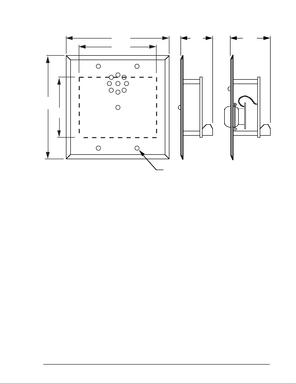
3.2.1 The receiver has a depth of approximately 1-1/4 inches, so a deep mounting
box with a minimum 2-inch depth is required. Critical mounting dimensions are shown
in Figure 3-1. Typical mounting boxes are as follows:
4” square, w/two-gang ring (Bowers #4-SDW and #408 or equivalent)
4” square, two-gang box, 2-1/8” deep (Bowers #132-W or equivalent)
NOTE: A mounting box deeper than 2-1/8" is recommended for the 03RM/IV
for additional cable clearance.
19
INSTALLATION AND OPERATION INSTRUCTIONS — PERSONAL ALARM SYSTEM
4.50
3.50
4.50
2.75
1.25
Circuit Board is Centered Relative
to Mounting Holes and Face Plate
Standard Two-Gang Mounting
(4 Holes)
1.81
(03RM/IV)
Figure 3-1 03RM Receiver Mounting Dimensions
3.2.2 Tamper switch activation is by way of two self-adhesive, permanent magnets supplied
with the receiver. Position these magnets on the inside surfaces of the box using the template
provided. See Figure 3.2.The receiver electronics are mounted to a combination trim and
mounting plate SS-040, which mates to standard two-gang boxes.

INSTALLATION AND OPERATION INSTRUCTIONS — PERSONAL ALARM SYSTEM
20
ALIGN TEMPLATE HOLES
WITH BOX HOLES
MARK BOTH RIGHT AND LEFT SIDES OF THE BOX BY ALIGNING TEMPLATE TO
EACH PAIR OF BOX HOLES.
STRIP BACKING PAPER FROM SELF-ADHESIVE MAGNETS AND CENTER
THEM AT MARKED LOCATIONS.
MARKING
TEMPLATE
1/2"
MARK MAGNET LOCATION
ALONG EITHER SIDE OF TEMPLATE
1/2" DOWN FROM MOUNTING SURFACE
1" DOWN FOR 03RM/IV
(1" for
03RM/IV)
Figure 3-2 Magnet Position for Tamper Switch Activation
3.2.3 Wiring connections are via a 10-position plug-in connector. Attach the
connector to the wiring before plugging connector into circuit board.The wiring must
be attached to the connector in accordance with Figure 3-3. Figure 3-3 shows wire
colors for the type of wire normally used. If the colors of your cable are different,
change the wire colors listed on Figure 3-3 and retain as your as-built information.
A blank space is provided for this purpose.
3.2.4 Pay particular attention to the shield wires at this end.The shields are not to be
connected but must be isolated from other wires or grounds.Trim shields short and
apply electrical tape to insulate.
Table of contents
Other SENSTAR Security System manuals


Popular Security System manuals by other brands

WERMA Signaltechnik
WERMA Signaltechnik 450 Series Instructions for use

Wearable Health Solutions
Wearable Health Solutions iHelp+ 3G Series owner's manual

Ritron
Ritron Quick Talk RQT-150 owner's manual

stabo
stabo WLAN indoorcam_fisheye quick start guide

Tyco
Tyco Visonic MC-302EL PG2 installation instructions

ZEPCAM
ZEPCAM Mobile Video Box M2 instruction manual


