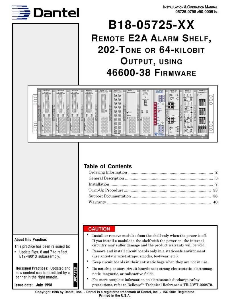
Dantel B15-00459-02 User manual

CAUTION
Install or remove modules from the shelf only when the power is off.
If you install a module in the shelf with the power on, the internal
circuitry may suffer damage and the product warranty will be void.
Remove and install circuit boards only in a static-safe environment
(use antistatic wrist straps, smocks, footwear, etc.).
Keep circuit boards in their antistatic bags when they are not in use.
Do not ship or store circuit boards near strong electrostatic, electromag-
netic, magnetic, or radioactive fields.
For more complete information on electrostatic discharge safety
precautions, refer to BellcoreTM Technical Reference #TR-NWT-000870.
Copyright 1999 by Dantel, Inc. • Dantel is a registered trademark of Dantel, Inc. • ISO 9001 Registered
Printed in the U.S.A.
INSTALLATION&OPERATION MANUAL
05725-02-0499<90-00201>
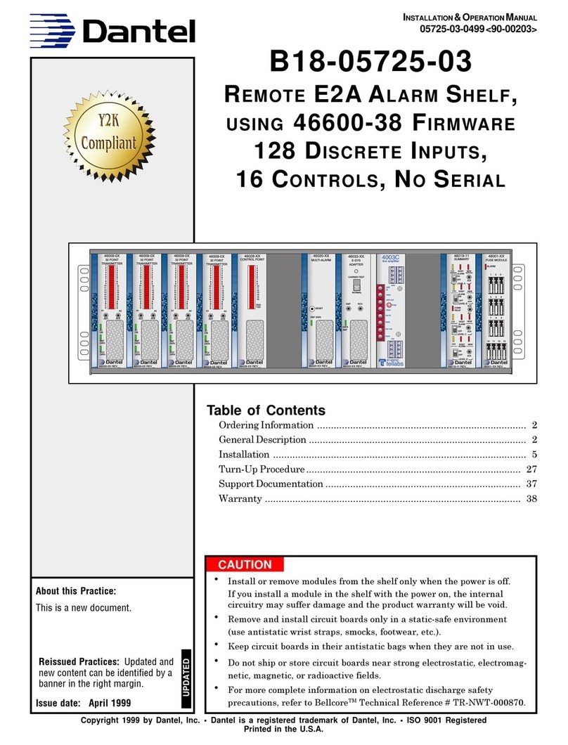
B18-05725-02
REMOTE E2A ALARM SHELF,
WITH 64-KILOBIT OUTPUT, USING
46600-38 FIRMWARE
64 DISCRETE INPUTS, 16
CONTROLS, NOSERIAL
About this Practice:
This is a new document.
Issue date: April 1999
Reissued Practices: Updated and
new content can be identified by a
banner in the right margin.
UPDATED
Table of Contents
Ordering Information ............................................................................ 2
General Description ............................................................................... 2
Installation ............................................................................................ 5
Turn-Up Procedure.............................................................................. 29
Support Documentation ....................................................................... 41
Warranty ............................................................................................. 42
xmt out
loop
mon
4003C
line amplifier
xmt
in
mon
tellabs
rcv in
mon
rcv out
mon
814003C
xmt
rcv
46009-0X
32 POINT
TRANSMITTER
1
2
3
4
5
6
7
8
9
10
11
12
13
14
15
16
A
B
C
D
1
2
3
4
5
6
7
8
9
10
11
12
13
14
15
16
A
B
C
D
A1 A2
RST ACK
A1
ON
XMT
DATA
RCV
DATA
46009-0X
32 POINT
TRANSMITTER
1
2
3
4
5
6
7
8
9
10
11
12
13
14
15
16
A
B
C
D
1
2
3
4
5
6
7
8
9
10
11
12
13
14
15
16
A
B
C
D
A1 A2
RST ACK
A1
ON
XMT
DATA
RCV
DATA
46020-XX
MULTI-ALARM
RESET
46033-XX
E-SYS
ADAPTER
XMT RCV
46105-XX
DUAL VF
RCV
MON DROP
XMT
RCV
XMT
CH 1
CH 2
MON DROP
46019-11
SUMMARY
LEVEL A
LEVEL B
LEVEL D
EXIST
ALARM
C/O NEW
ON
OFF ACK
LEVEL C
48001-XX
FUSE MODULE
123
456
789
10 11 12 13
12 7
8
9
10 11 12
46009-0X REV__ 46009-0X REV__ 46020-XX REV__ 46033-XX REV__ 46105-XX REV__ 46019-11 REV__ 48001-XX REV__
XMT DATA
DATA
XMT
CARRIER TEST
NORMAL
XMT
RCV
SYNC
RCV LVL
GND
XMT
RCV
SYNC
RCV LVL
GND
EXIST
ALARM
C/O NEW
ON
OFF ACK
EXIST
ALARM
C/O NEW
ALL
ON
OFF ACK
EXIST
ALARM
C/O NEW
ON
OFF ACK
ACK
COMM
RELAY
ALARM
46028-XX
CONTROL POINT
1
2
3
4
5
6
7
8
9
10
11
12
13
14
15
16
RXD
TXD
5
46028-XX REV__

PAGE 2 05725-02-0499<90-00201>
ORDERING INFORMATION
NOTE: This section lists the different options available for this product. To order any of the available
options, contact Dantel Inside Sales through our toll-free number, 1-800-432-6835.
OPTION NUMBER FEATURES
B18-05725-02 64 discrete alarms, 16 control points, terminal port for access, E2A output, 64 KB digital
output, cross-connect block and four 25-foot cables
GENERAL DESCRIPTION
T
he 05725 Remote E2A shelf is a 12-position 460 Alarm and
Control System (ACS) shelf. This shelf collects discrete alarm
data from central office communications equipment. The alarm
data is processed, concentrated, and converted to E2A protocol for
transmission to the host computer at the Alarm Center. For a
functional schematic of this shelf, refer to sheet 2 of 3 of the
B18-05725-XX drawing that accompanies this Application Manual.
The -02 option is equipped with a 46105 Dual VF 64-kilobit Chan-
nel Module. The output of this shelf is a digital signal that can be
transmitted over a 56K or 64K digital service channel.
MODULES
This shelf, like many Dantel shelves is made up of separate plug-
in modules that are factory-wired together to accomplish a task.
The modules used in the 05725-02 shelf are described below and
shown in Fig. 1.
Multiple Alarm Transmitters (MATs) - slots 1-2
Each MAT:
♦Reports the alarm status for up to 32 independent discrete
alarm inputs
♦Provides LEDs to indicate active alarms.
NOTE: Slots 3 and 4 are wired for MATs only and not equipped.
Control Point Module (CPM) - slot 5
The CPM provides 16 discrete (independent) relays controllable by
the MAP. Commands can be entered from the Printer Port of the
MAP using a dumb terminal (refer to 46020-38 manual), or by the
Alarm Center. Any of the 16 control points can be turned on or off
to control a particular piece of equipment.

05725-02-0499<90-00201> PAGE 3
Multiple Alarm Combiner (MAC) - slot 6
Slot 6 is wired only and not equipped.
Multiple Alarm Processor (MAP) - slot 7
The MAP is the center of the Dantel system. The MAP:
♦Polls (interrogates) remote alarm reporting equipment
♦Operates control points
♦Reports alarm status to the Alarm Monitoring Center (FMAC)
The MAP uses three ports to receive and transmit information:
♦The Data Port connects the MAP to the Control Point Module
(CPM) and Multi Alarm Transmitters (MATs) .
♦The Printer Port, (also called the Craft, Configuration, or Inter-
face Port), is used for local monitoring and configuring of the
MAP. A serial printer can be connected here to obtain a
hardcopy printout of the alarm information.
♦The Master Port is used to report the alarm information to the
alarm center through the E-System Adapter.
The Master Port provides mounting for the RS-232 subassem-
bly.
E-System Adapter (ESA) - slot 8
The ESA provides an interface between the MAP(s) and the TNC.
It:
♦Takes the DCP protocol from the MAP and converts it to E2A
♦Provides mounting for a 202 Tone Modem.
It then sends that information to the Alarm Center.
Tellabs 4003C Line Amplifier - slot 9
The 4003C Line Amplifier with Loopback provides:
♦Switch-selectable level control.
♦Equalization.
♦Impedance matching in transmit and receive channels.
♦Tone-activated or dc-activated equal-level loopback of the facil-
ity.
Dual VF 64-Kilobit Channel (64KB) - slot 10
The 64KB interfaces analog voice or data equipment to a
64-kilobit digital service channel equipment. The module has two
channels which operate independently or interconnected in bridge
configuration.
GENERAL DESCRIPTION

PAGE 4 05725-02-0499<90-00201>
GENERAL DESCRIPTION
Summary Alarm Module (SAM) - slot 11
This module provides a means to control an audible and/or visual
alarm device for four alarm levels (A,B, C, and D). Wired to, and
controlled by, the MAP in slot 7, the SAM provides four indepen-
dent form C relays.
Fuse Module - slot 12
The B11-48001-01 Fuse Module provides 13 GMT indicating-type
fuse circuits and a failure alarm circuit for fusing 400-type mod-
ules in an equipment shelf. The module fits into any 400-type or
similar equipment housing and operates on -21 to -56 VDC input
power. The front panel includes 13 indicating-type GMT fuses and
an alarm LED.
This application uses the Fuse Modules redundant inputs. Con-
necting one power supply as Source A, and a second power supply
as Source B parallels both supplies. Refer to Fig. 2.
FIG. 1 - 05725-02 SHELF FRONT VIEW
xmt out
loop
mon
4003C
line amplifier
xmt
in
mon
tellabs
rcv in
mon
rcv out
mon
814003C
xmt
rcv
46009-0X
32 POINT
TRANSMITTER
1
2
3
4
5
6
7
8
9
10
11
12
13
14
15
16
A
B
C
D
1
2
3
4
5
6
7
8
9
10
11
12
13
14
15
16
A
B
C
D
A1 A2
RST ACK
A1
ON
XMT
DATA
RCV
DATA
46009-0X
32 POINT
TRANSMITTER
1
2
3
4
5
6
7
8
9
10
11
12
13
14
15
16
A
B
C
D
1
2
3
4
5
6
7
8
9
10
11
12
13
14
15
16
A
B
C
D
A1 A2
RST ACK
A1
ON
XMT
DATA
RCV
DATA
46020-XX
MULTI-ALARM
RESET
46033-XX
E-SYS
ADAPTER
XMT RCV
46105-XX
DUAL VF
RCV
MON DROP
XMT
RCV
XMT
CH 1
CH 2
MON DROP
46019-11
SUMMARY
LEVEL A
LEVEL B
LEVEL D
EXIST
ALARM
C/O NEW
ON
OFF ACK
LEVEL C
48001-XX
FUSE MODULE
123
456
789
10 11 12 13
12 7
8
9
10 11 12
46009-0X REV__ 46009-0X REV__ 46020-XX REV__ 46033-XX REV__ 46105-XX REV__ 46019-11 REV__ 48001-XX REV__
XMT DATA
DATA
XMT
CARRIER TEST
NORMAL
XMT
RCV
SYNC
RCV LVL
GND
XMT
RCV
SYNC
RCV LVL
GND
EXIST
ALARM
C/O NEW
ON
OFF ACK
EXIST
ALARM
C/O NEW
ALL
ON
OFF ACK
EXIST
ALARM
C/O NEW
ON
OFF ACK
ACK
COMM
RELAY
ALARM
46028-XX
CONTROL POINT
1
2
3
4
5
6
7
8
9
10
11
12
13
14
15
16
RXD
TXD
5
46028-XX REV__
64 discrete alarm
points (32 per
card). Note that
the cards are not
interchangeable
without changing
addresses.
16 control
points
Central
processor
and RS-232
subassembly
E-System
Adapter and
202 Tone
Modem
4-wire
interface and
loopback unit
64 kilobit unit
Visual alarm
indicator
Fuse panel

05725-02-0499<90-00201> PAGE 5
This section consists of three parts:
1. Equipment Mounting
2. Wiring
3. Switch and Strap Settings
46009 Multiple Alarm Transmitter
46028 Control Point Module
46020-38 Multiple Alarm Processor with Firmware
46029 RS-232 Current Loop Interface Subassembly
46033 E-System Adapter
49013 202 Tone Modem Subassembly
Tellabs 4003C
46105 Dual VF 64-kilobit Channel
46019 Summary Alarm Module
48001 Fuse Module
4. Summary of Switch Settings
EQUIPMENT MOUNTING
Tools Required:
♦Ohmmeter
♦Phillips screwdriver
♦7/16" Nutdriver or socket wrench
♦(TMS) Transmission measuring Set
Visually inspect shelf for obvious damage.
Use ohmmeter to check for a short across the power input at A
and B (-DC) and (GND) at the left end of the rear of the shelf (refer
to Fig. 2).
TMS is used to verify the levels at the output of the 46033
E-System Adapter and the 4003C Line Amplifier.
INSTALLATION

PAGE 6 05725-02-0499<90-00201>
FIG. 2 - REAR VIEW OF 05725 SHELF
With a Phillips screwdriver, mount the shelf in an equipment rack
using the screws and lockwashers supplied in a bag attached to
the side of the shelf.
Mounting hardware is supplied in a bag attached to the side of the
shelf.
Refer to Figure 3.
INSTALLATION
FA
FB
C
B
1
25
116
TB 116
TB
15 30 15 30
C1
C2
C3
C4
TB
1
2
3
4
5
6
7
8
9
10
A
B
E
F
C5 C6 C7 C8
C1
C2
C3
C4
PANEL D PANEL C PANEL B PANEL A
-DC
GND 111 1
1
25
50 26
XMIT REC
LINE (ZAET Circuit)
LIST
13
CABLS
,
M
/
F
CONNECTOR
25
FT
LENGTH
PART
NUMBER
26-49020-25
LIST 11
TS 1 BLOCK
PART NUMBER
25-00710-00
(A) (B) (C) (D)
BOTTOM
FRONT
Alarm
Points
1-32
Alarm
Points
32-64
(65 to
96 not
used)
Alarm
Points
97-128
(not
used)
Control
Points
1-16
-BATTERY
(Source A)
RTTR
-BATTERY
(Source B)
GND
Connect to 64kb Channel
Connect to 64kb Channel
(if repeater)

05725-02-0499<90-00201> PAGE 7
FIG.3-MOUNTING CONFIGURATION,41075400-TYPE MOUNTING
INSTALLATION
1. Facing the frame rail, place the equipment shelf in the rack in the
desired location. Secure with three Phillips-head screws and
lockwashers - two on the right side, top and bottom, and one on the
lower left side.
2. Install one ESD stud, with lockwasher, in the upper left location.
3. Secure all fasteners tightly, ensuring proper grounding between ESD
stud and frame rail.
4. Place ESD label next to the ESD stud.
5. From the rear of the bay, install the other ESD stud and lockwasher
into the frame rail next to the equipment shelf. Secure tightly, ensur-
ing proper grounding of the ESD stud. Place ESD label next to the
ESD stud.
WIRING
Wire the 05725 Remote E2A Alarm Shelf to external equipment as
required. Use the B18-05725-XX Block and Level Drawing as a
reference for making connections to Dantel equipment.
Refer to interconnect wiring diagram Fig 4. This will help under-
stand and read the circuit diagrams.
64kb Channel
♦Connect to C1-B for terminal application.
♦Connect to C1-B and C2-B for repeater application.

PAGE 8 05725-02-0499<90-00201>
INSTALLATION
FIG.4- 05725INTERCONNECT DIAGRAM
8A
8B
8C
8D
4003c
TELLABS
7A
7B
7C
7D
6A
6B
6C
6D
E-SYS
ADAPTER
5E
5F
4B
4C
MAP MAC
Optional TB-A TB-A
2A
2B
2C
2D
3A
3B
3C
3D
CPM
TB-A
5B
5D
5A
5C 29
30
MAT MAT
WIRING ADDED WHEN
PANEL IS NOT EQUIPPED
WITH A MAC CARD
12345678910
A
B
C
D
E
F
TB-A
TERMINAL STRIP
BACKPLANE IN PANEL A
INDICATES WIRE STRAPS
TB-D
GND
TB-A TB-A TB-A TB-A TB-A
9A
9B
9C
9D
05725-02
C1-B
C1-A
64 KB Channel
64 KB Channel
11
3
12
4
14
6
9
1
11
3
12
4
14
6
9
1
46105
64kB

05725-02-0499<90-00201> PAGE 9
STRAP AND SWITCH SETTINGS
46009 Multiple Alarm Transmitter (MAT)
Refer to Fig. 5 and Table A.
FIG. 5 - 46009 MAT SWITCH AND STRAP LOCATIONS
INSTALLATION
1 2 3 4
1 2 3 4 5 6 7 8
1 2
1 2 3 4 5 6 7 8 1 2 3 4 5 6 7 8
BOTTOM EDGE
*S5 S4 S3
* Shown for display 5 points 1-32.
TOP EDGE
B A
S6
S301

PAGE 10 05725-02-0499<90-00201>
TABLE A - 46009 MAT SWITCH AND STRAP OPTIONS
INSTALLATION
SWITCH
SW5
Slot 1 **
Slot 2 ***
SW4
SW3
SW6
SW301
POSITION
12345678
01101111
01101101
11010001
01111111
1111----
01------
NOTE: A 1 indicates that the switch is up (up = OFF). A 0
indicates that the switch is down (down = ON).
** DCM addresses 17/18 (display 5, bits 1-32)
*** DCM addresses 19/20 (display 5, bits 33-63)
NOTE: The MATs in slots 1 and 2 are not interchangeable without changing
the address on switch 5 first.
46028 Control Point Module (CPM)
Refer to Fig. 6 and Table B.
FIG. 6 - 46028 CPM SWITCH AND STRAP LOCATIONS
113
1
4
J5
J4
SUBASSEMBLY
MOUNTING
AREA
OFF
18
OFF
18
S1 S2
UP=OFF
DOWN=ON
A
NORM
REV
S3
B
Bottom Edge View
SWITCH 1 SWITCH 2
UP = OFF
DOWN = ON
1 2 3 4 5 6 7 8 1 2 3 4 5 6 7 8

05725-02-0499<90-00201> PAGE 11
TABLE B - 46028 CPM SWITCH AND STRAP OPTIONS
INSTALLATION
NOTE: A 1 indicates that the switch is up (up = OFF).
A 0 indicates that the switch is down (down = ON).
SWITCH
SW1
SW2
S3
AB
Strap
POSITION
12345678
10000000
11111111
Leave in NORM
Leave in A position.
46020-38 Multiple Alarm Processor (MAP)
Refer to Figs. 7 and 8, and Tables C and D.
FIG. 7 - 46020 MAP SUBASSEMBLY AND SWITCH LOCATIONS
DATA
XMT
LED
COMMUNICATIONS
SUBASSEMBLY
MOUNTING
RESET SWITCH
8765432187654321
S4 S3 S2
8765432187654321
S1
87654321
S7
87654321
S5
8 7 6 5 4 3 2 1
S6
FIRMWARE
SUBASSEMBLY

PAGE 12 05725-02-0499<90-00201>
INSTALLATION
FIG. 8 - 46020 MAP VIEWED FROM THE TOP
VIEW
ROTATED
90 DEGREES
*
REFER TO NOTE BELOW
1 2 3 4 5 6 7 8 1 2 3 4 5 6 7 8 1 2 3 4 5 6 7 8 1 2 3 4 5 6 7 8
1 2 3 4 5 6 7 8
1 2 3 4 5 6 7 8
SWITCH 7
SWITCH 6
SWITCH 1 SWITCH 2 SWITCH 3 SWITCH 4
UP = OFF
DOWN = ON
1 2 3 4 5 6 7 8
SWITCH 5*
1 2 3 4 5 6 7 8
1 2 3 4 5 6 7 8
1 2 3 4 5 6 7 8
NOTE: Apply power initially with switch 5 position 7 UP and allow the
MAP to self-configure. Then remove power and place switch 5
position 7 DOWN. This will retain the configuration in
memory.
TABLE C - SWITCHES 1 THRU 4, 46020-38
SWITCH
SW5
SW6
SW7
POSITION
12345678
111111*0
11111111
11111111
* NOTE: Switch 5 position 7 must be up to configure on initial
power-up. Place down to retain configuration in memory. A 1
indicates that the switch is up (up = OFF). A 0 indicates
that the switch is down (down = ON).
NOTE: A 1 indicates that the switch is up (up = OFF). A
0 indicates that the switch is down (down = ON).
SWITCH
SW1
POSITION
12345678
00000000
SW2 00000100
SW3 00000000
SW4 00000001
TABLE D - SWITCH 5-7, 46020-38

05725-02-0499<90-00201> PAGE 13
INSTALLATION
49029 RS-232 Current Loop Interface Subassembly
Refer to Fig. 9 and Table E.
FIG. 9 - 49029 SWITCH AND STRAP POSITIONS
X2 X1
X3
12 3
P4
-00 -01
S1
ON
CTS
THRU
DCD
P5
TABLE E- 49029SWITCH AND STRAP SETTINGS
OPTION
Normal Position *
TXD, RXD, RTS, and DCD reversed
CTS used for handshaking
CTS not used for handshaking *
DCD used for handshaking
DCD not used for handshaking *
Parallel Option
YES
NO *
SWITCH OR STRAP SETTINGS
S1 - -00 Mode
S1 - -01 Mode
X1 - THRU
X1 - ON
X2 - THRU
X2 - ON
X3 - Jumper pins 2 & 3
X3 - Jumper pins 1 & 2
NOTE:
Default switch and strap positions
are indicated by a *. For more
detail and further explanations
about the individual modules, re-
fer to the practices specific to that
module.

PAGE 14 05725-02-0499<90-00201>
CONTINUED . . .
INSTALLATION
46033 E-System Adapter
Refer to Fig. 10 and Tables F and G
FIG. 10 - 46033 E-SYSTEM ADAPTER SWITCH LOCATIONS
SWITCH
SW1
SW2
SW3
SW4
POSITION
12345678
11110001
Station Address. Refer to Table F.
10100000
01111111
NOTE: A 1 indicates that the rocker switch is up adjacent to
the position number (open = OFF). A 0 indicates that the rocker
switch is down adjacent to the position number (closed = ON).
1234567812345678
12345678
12345678
S2 S3 S4
ON = Closed
OFF = Open
S1
Refer to Table G
NOR
RCV
S2
113
P5
1
4
P4
MAS SLA
XMT RCV
MAS SLA
OUT
IN IN
U2
U1
-00
-01
*
TABLE F - 46033 E-SYSTEM ADAPTER SWITCH SETTINGS

05725-02-0499<90-00201> PAGE 15
CONTINUED . . .
INSTALLATION
TABLE G - 46033 E-SYSTEM ADAPTER S2 SWITCH SETTINGS
ADDRESS
00
01 *
02
03
04
05
06
07
08
09
10
11
12
13
14
15
16
17
18
19
20
21
22
23
24
25
26
27
28
29
30
31
POSITION
1234567 8
00000000
00000001
00000010
00000011
00000100
00000101
00000110
00000111
00001000
00001001
00001010
00001011
00001100
00001101
00001110
00001111
00010000
00010001
00010010
00010011
00010100
00010101
00010110
00010111
00011000
00011001
00011010
00011011
00011100
00011101
00011110
00011111
NOTE:
A 0 indicates that the
rocker switch is down
adjacent to the position
number (closed = ON).
A 1 indicates that the
rocker switch is up adja-
cent to the position num-
ber (open = OFF).
* = Factory Default

PAGE 16 05725-02-0499<90-00201>
CONTINUED . . .
INSTALLATION
TABLE G (CONTINUED) - 46033 E-SYSTEM ADAPTER S2 SWITCH SETTINGS
NOTE:
A 0 indicates that the
rocker switch is down
adjacent to the position
number (closed = ON).
A 1 indicates that the
rocker switch is up adja-
cent to the position num-
ber (open = OFF).
ADDRESS POSITION
12345678
32
33
34
35
36
37
38
39
40
41
42
43
44
45
46
47
48
49
50
51
52
53
54
55
56
57
58
59
60
61
62
63
64
65
66
67
68
69
70
71
72
73
74
75
00100000
00100001
00100010
00100011
00100100
00100101
00100110
00100111
00101000
00101001
00101010
00101011
00101100
00101101
00101110
00101111
00110000
00110001
00110010
00110011
00110100
00110101
00110110
00110111
00111000
00111001
00111010
00111011
00111100
00111101
00111110
00111111
01000000
01000001
01000010
01000011
01000100
01000101
01000110
01000111
01001000
01001001
01001010
01001011

05725-02-0499<90-00201> PAGE 17
CONTINUED . . .
INSTALLATION
ADDRESS POSITION
12345678
76
77
78
79
80
81
82
83
84
85
86
87
88
89
90
91
92
93
94
95
96
97
98
99
100
101
102
103
104
105
106
107
108
109
110
111
112
113
114
115
116
117
118
119
01001100
01001101
01001110
01001111
01010000
01010001
01010010
01010011
01010100
01010101
01010110
01010111
01011000
01011001
01011010
01011011
01011100
01011101
01011110
01011111
01100000
01100001
01100010
01100011
01100100
01100101
01100110
01100111
01101000
01101001
01101010
01101011
01101100
01101101
01101110
01101111
01110000
01110001
01110010
01110011
01110100
01110101
01110110
01110111
NOTE:
A 0 indicates that the
rocker switch is down
adjacent to the position
number (closed = ON).
A 1 indicates that the
rocker switch is up adja-
cent to the position num-
ber (open = OFF).
TABLE G (CONTINUED) - 46033 E-SYSTEM ADAPTER S2 SWITCH SETTINGS

PAGE 18 05725-02-0499<90-00201>
CONTINUED . . .
INSTALLATION
ADDRESS POSITION
12345678
120
121
122
123
124
125
126
127
128
129
130
131
132
133
134
135
136
137
138
139
140
141
142
143
144
145
146
147
148
149
150
151
152
153
154
155
156
157
158
159
160
161
162
163
01111000
01111001
01111010
01111011
01111100
01111101
01111110
01111111
10000000
10000001
10000010
10000011
10000100
10000101
10000110
10000111
10001000
10001001
10001010
10001011
10001100
10001101
10001110
10001111
10010000
10010001
10010010
10010011
10010100
10010101
10010110
10010111
10011000
10011001
10011010
10011011
10011100
10011101
10011110
10011111
10100000
10100001
10100010
10100011
NOTE:
A 0 indicates that the
rocker switch is down
adjacent to the position
number (closed = ON).
A 1 indicates that the
rocker switch is up adja-
cent to the position num-
ber (open = OFF).
TABLE G (CONTINUED) - 46033 E-SYSTEM ADAPTER S2 SWITCH SETTINGS

05725-02-0499<90-00201> PAGE 19
CONTINUED . . .
INSTALLATION
ADDRESS POSITION
12345678
164
165
166
167
168
169
170
171
172
173
174
175
176
177
178
179
180
181
182
183
184
185
186
187
188
189
190
191
192
193
194
195
196
197
198
199
200
201
202
203
204
205
206
207
10100100
10100101
10100110
10100111
10101000
10101001
10101010
10101011
10101100
10101101
10101110
10101111
10110000
10110001
10110010
10110011
10110100
10110101
10110110
10110111
10111000
10111001
10111010
10111011
10111100
10111101
10111110
10111111
11000000
11000001
11000010
11000011
11000100
11000101
11000110
11000111
11001000
11001001
11001010
11001011
11001100
11001101
11001110
11001111
NOTE:
A 0 indicates that the
rocker switch is down
adjacent to the position
number (closed = ON).
A 1 indicates that the
rocker switch is up adja-
cent to the position num-
ber (open = OFF).
TABLE G (CONTINUED) - 46033 E-SYSTEM ADAPTER S2 SWITCH SETTINGS

PAGE 20 05725-02-0499<90-00201>
INSTALLATION
ADDRESS POSITION
12345678
208
209
210
211
212
213
214
215
216
217
218
219
220
221
222
223
224
225
226
227
228
229
230
231
232
233
234
235
236
237
238
239
240
241
242
243
244
245
246
247
248
249
250
251
11010000
11010001
11010010
11010011
11010100
11010101
11010110
11010111
11011000
11011001
11011010
11011011
11011100
11011101
11011110
11011111
11100000
11100001
11100010
11100011
11100100
11100101
11100110
11100111
11101000
11101001
11101010
11101011
11101100
11101101
11101110
11101111
11110000
11110001
11110010
11110011
11110100
11110101
11110110
11110111
11111000
11111001
11111010
11111011
NOTE:
A 0 indicates that the
rocker switch is down
adjacent to the position
number (closed = ON).
A 1 indicates that the
rocker switch is up adja-
cent to the position num-
ber (open = OFF).
TABLE G (CONTINUED) - 46033 E-SYSTEM ADAPTER S2 SWITCH SETTINGS
Table of contents
Other Dantel Security System manuals
Dantel
Dantel 46022-30 User manual
Dantel
Dantel 46022-12 User manual
Dantel
Dantel A23-41073 User manual
Dantel
Dantel A23-41073-00 User manual
Dantel
Dantel B18-05725-03 User manual
Dantel
Dantel B23-41070 User manual
Dantel
Dantel B23-41071 User manual
Dantel
Dantel RemoteMaster 46132-41 User manual
Dantel
Dantel A18-05775 Series User manual
Dantel
Dantel 46022-20 User manual
Popular Security System manuals by other brands

First Alert
First Alert DWB-700 user manual

Tyco Security Products
Tyco Security Products DSC PowerSeries Neo HS2016 user guide
Cooper Security
Cooper Security M-Series user guide

ELRO
ELRO AS80SR11A installation instructions
Dormakaba
Dormakaba Combi B Alarm box Mounting instruction

NUUO
NUUO NAS NVRmini user manual
