Sentec LS-700 Series User manual

Half
Range
・Please carry out independent wiring of the sensor-head
aside from other power lines. ・Please refer to an attached characteristic
data sheet.
(It is when a part is not appended.)
DIN rail attachment is possible.
DIN standard:based on 46277
3m of standard coaxial cord is attached to each sensor-head.
SP(high resolution):0.03% of F.S (0.3μm, minimum)
Disconnection of a sensor-head or poor connection is detected.(NPN open-collector transistor)
250mA or less
DC12-24V ±10% Ripple 10% or less
35~85%RH(no condensation)
CONTROLLER:-10~+60℃ SENSOR-HEAD:-20~+70℃
CONTROLLER:0.01% of F.S/℃ SENSOR-HEAD:0.02% of F.S/℃
MEASURING RANGE
HA-30S
HA-50S
HA-80S HA-101S
HA-141S HA-225S
※1
※2
ITEM
※3 0~0.8mm 0~1mm 0~2mm 0~3.5mm 0~5mm 0~10mm
0~0.8V 0~1V 0~2V 0~3.5V 0~5V 0~10V
±1% of F.S ※4
0.03% of F.S (0.3μm, minimum) ※5
DC~10kHz (-3dB)
52Ω
※6
※8
●
記号
型式 ABC
HA-30S
HA-50S
HA-80S
3.6 2.6
5.4 3.2
8
15
15
15 3.2
・HA-101S、141S
3
BC
・HA-30S~80S
・HA-225S
φA
B
φC
・HA-162S
614 5
3
φ3.2
φ3.2
対辺21
M16,P=1.0
・HA-222R
14
8
18
φ3.2
対辺19
M14,P=1.0
22
5.
5 5.
5
3.
8
4
3
4.
5
22
φ2.6
2-φ3.5
2-φ6
0 0 0 0
Voltage-meter
Target
(2)SPAN-Adjustment
Please contact a sensor at a target.
Please turn 0-ADJ so that analog output voltage
becomes 0V.
Target
Please set a sensor-head as the distance of the
half of the measurement target range.
Please rotate SPAN-ADJ so that you may become a
voltage value suitable for the distance.
(ex 1mm=1.000V)
NOTES)Please repeat ZERO-ADJ and SPAN-ADJ
2to3 times.
Controller
Sensor
head
記号
型式 A B C
HA-101S
HA-141S
M10,P=1.0 12 3
515
D
14
19M14,P=1.0
A
対辺D
(unit:mm)
3
(unit:mm)
- +
V13231
S P A N
0-A DJ
POWER
DZ
ALARM
SC
TC
LS-700
①②③④⑤⑥⑦⑧⑨
⑩⑪⑫⑬⑭⑮⑯⑰⑱
※7
S P A N
0-ADJ
POWER
DZ
ALARM
SC
TC
LS-700
54
S P A N
0-ADJ
POWER
DZ
ALAR M
SC
TC
LS -700
0 0 0 0
Voltage-meter
Controller
Sensor
head
S P A N
0-ADJ
POWER
DZ
ALAR M
SC
TC
LS -700
①
②
③
④
⑤
⑥
⑦
①Power indicator
②Alarm indicator
③Span-adjustment trimmer
④Zero-adjustment trimmer
⑤Digital zero control
changeover switch
⑥Digital zero indicator
⑦Digital zero switch
14.
5
61
(1)ZERO-Adjustment
(When 0-ADJ is used.)
Thank you for purchasing this product.
In order to use this specification, fully satisfying
it, please use a handling description on looking well.
CE-Marking Correspondence article EMC directive (2004/108/EC):EN61000-6-4(EMI),EN61000-6-2(EMS).
The test is not application to D.C power input ports intended to be permanently connected to cables less than in
10m length.
Please make into a length of less than 10m the code which connects a controller with a direct-current power supply.
There is no compatibility between sensors-head.
Change of the length of the code of a sensor changes the characteristic. (The standard length is 3m.)
When length is changed, please contact our sales department.
It is the case where an adjustment subject is iron.
The material of iron of our standard adjustment subject is SS400.
When an adjustment object is not iron, The lineality of LS-700-08 is set to of ±2% of F.S.
LPF (Low Pass Filter) the static minimum at the time of use-it is resolution Please specify SP type of an option.
A standard machine is of F.S 0.1% (1μm of resolution [Minimum]).
It is the case where the length of coaxial cord is standard specification (3m), and an adjustment subject is iron.
It is chosen whether digital zero are controlled by the digital zero control changeover switch of a panel side with
digital zero switch of a panel side, or digital zero terminal performs.
When a changeover switch is made into the SC side, it becomes control with digital zero switch, and when it turns
on the TC side, it becomes control with digital zero terminal.
When controlling digital zero by digital zero switch, once it pushes digital zero switch, the digital zero function
will operate, and it will be canceled if it pushes once again.
When controlling digital zero by digital zero terminal, it will be canceled, if digital terminal and COM terminal
are short-circuited and digital zero function will operate and open.
During digital zero functional operation, the digital zero indicator beside digital zero switch lights up.
At the time of detection, the alarm indicator of a panel side lights up.
DIGITAL ZERO FUNCTION The present output value is made into zero. Error ±0.1% of F.S
ALARM OUTPUT
OUTPUT VOLTAGE
LINEARITY
RESOLUTION
RESPONSE
OUTPUT IMPEDANCE
STABILITY
AMBIENT HUMIDITY
AMBIENT TEMPERATURE
POWER
CONSUMPTION
OPTION
DC12-24V
POWER
Analog
V-OUT
DC40V
100mA
※Nothing connects with
③ and ④ terminal.
Digital zero
control terminal
Alarm output
5mm or more Use a flat tip M3 screw to secure the sensor-head.
Notes)When the sensor-head of HA-162S and HA-222R is embedded,
please contact our sales department.
2-t h roug h bore for M 4
・Since the controller is adjusted according to the
sensor-head, use which changes other sensor-head
and cable length of form cannot be performed.
・Since there is fear of mutual interference when
using it, making a sensor-head approach, please
contact our sales department.
4-4-24,NISHINAKAJIMA,YODOGAWA-KU,
OSAKA 532-0011 JAPAN
Tel.06(6304)8858 Fax.06(6302)0700
URL http://www.sentec.co.jp/
OUTPUT
(%)
φB/φA
100
80
60
40
20
1 2
Shield
Non-shield
φBφA
SENSOR
φB/φA
100
80
60
40
20
12 3 4 5 6 7
φB
φA
SENSOR
OUTPUT
(%)
MEASUREMENT(mm)
2
1
1(F.S) 2
Al
Cu
Fe
sus304
OUTPUT
Zero adjustment and Span
adjustment are the graph
set up similarly to an
iron state.
Zero-ADJ Range
Measure(mm)
Standard
Span-ADJ Range
10
0
-3dB
Frequency(kHz)
52
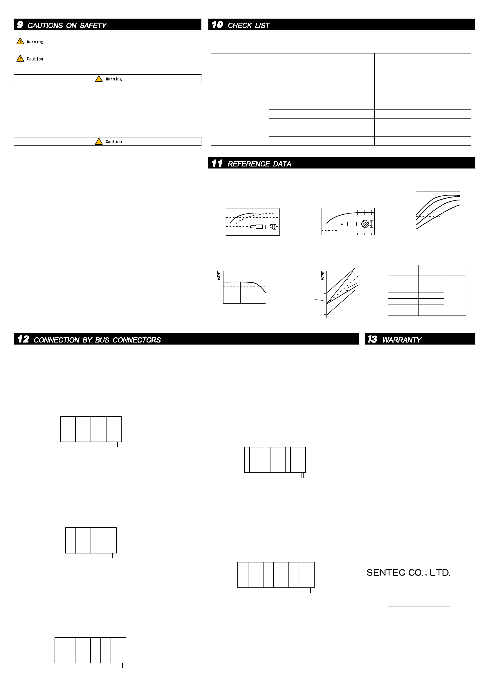
(2)In case a subject is a pillar
A specification value will be satisfield,
if the diameter of the piller of a subject
is by the thing which has 5 or more times
of the diameter of a sensor head.
(1)For the area of subject
A specification value will be satisfied,
if a subject is a thing which has more
than the diameter of the following graph
when a subject is used as a disk.
(4)Response For Frequency
CONTROLLER-TYPE Zero-ADJ
Range(V)
Span-ADJ
Range
LS-700-08
LS-700-1
LS-700-2
LS-700-4A
LS-700-4B
LS-700-10
-0.4~+0.4
-0.4~+0.4
-0.8~+0.4
-2.0~+0.5
-1.5~+0.8
-4.0~+1.0
0.8~1.2
times
(5)ZERO-Adjustment・Span-Adjustment Range
S y m p t o m C a u s e Countermeasure
●Power indicator does not
light after power supply
is turned on.
●Output voltage does not
reach volume described
in specifications.
●ZERO-adjust and/or SPAN-
adjust not possible.
●Power line is unplugged, or power supply
terminal plug is defective.
●Sensor cord is of inappropriate length.
●Sensor wire is laid too close to other wires. ●Lay sensor wire separately from other wires.
●Controller is not compatible with sensor
other than that specified.
Use appropriate sensor.
●Equipment is designed to sense iron.
Use only for iron.
●Plug in power line property, following
instruction display.
●Replace with cord of specified length.
●Object to be sensed is material other than iron.
●Volume of subject to be sensed is less than the
standard.
●Sensor is different from that specified.
●See reference data.
●The guarantee of the product is the one to mean the
guarantee of this machine unit.
●We will make the term of a guarantee of a product
into after-shipment one year.
●When failure arises by a manufacturer's responsibi-
lity during the above-mentioned term of a guarantee,
repair of the failure portion of a product or compo-
nent replacement is performed.
However, when it corresponds to below, We will carry
out the outside of the scope of a guarantee.
①When based on unsuitable condition, environment,
handing, and use of those other than the contents
checked by the specification value of a product,
the specifications exchaged separetely, etc.
②When the cause of failure is based on reasons other
than supplies.
③By remodeling or repairing the delivery goods that
depend besides our company.
④When based on the reason which was not able to be
foreseen with the technical level at the time of
the shipment.
⑤In addition, when it is not in the responsibility
by the side of a manufacturer with a natural disas-
ter, disaster, etc.
●We can do neither conformity in the particular appli-
cation of this machine, nor compensation of guarantee
loss of the secondary value generated with a product.
Moreover, they are not a design and the manufactured
product for the purpose of the use as which very high
reliability and safety are required, and the uses
(atomic power, aerospace, infrastructure, medical equ-
ipment, etc.) concerning a human life.
About the use under such a use and environment, we
will carry out the outside of the scope of a guaran-
tee.
LS-700-5 -2.4~+1.0
※Zero-ADJ Range:When 0-ADJ is used.
The following symptoms are often mistaken for product failure.
Check the following before bringing equipment in for repair.
LS-700LS-700LS-700LS-700
①LS-700 multiple connection (power supply package supply)
Four-set simultaneous connection is possible including what wired
the power supply.
The above-mentioned number is the number it will be whose power
supply voltage at DC12V.
Wiring of a power supply is possible by every controller.
POWER
②DLC-500 (digital linear converter) connection
It sees from the front and connects DLC-500 to the left-hand side
of LS-700.
It shall be one set which was combined with DLC-500, and two-set
simultaneous connection is possible.
The above-mentioned number of sets is the number of sets at power-
supply-voltage DC12V.
The input of DLC-500 turns into an output of LS-700.
Wiring of a power supply is connected to LS-700.
Since there is possibility of the power supply line damage by fire
on a substrate when it is connected with DLC-500, please be sure
to connect with LS-700.
LS-700
DLC-
500
POWER
③DLC-500 and CH-500 (comparator module) connection
It sees from the front, and DLC-500 is connected to the left-hand
side of LS-700, and also CH-500 is connected to left-hand side.
The combination of three sets shall be one set and two-set simul-
taneous connection is possible.
The above-mentioned number of sets is the number of sets at power-
supply-voltage DC12V.
The input of DLC-500 turns into an output of LS-700.
Wiring of a power supply is connected to LS-700.
Since the power supply line on a substrate may be damaged by fire
when it is connected with other controllers, please be sure to
connect with LS-700.
LS-700
DLC-
500
POWER
CH-
500
LS-700
DLC-
500
CH-
500
④VI-300 (signal converter) connection
It sees from the front and connects VI-300 to the left-hand side
of LS-700.
It shall be one set which was combined with VI-300, and three-set
simultaneous connection is possible.
The above-mentioned number of sets is the number of sets at power-
supply-voltage DC12V.
The input of VI-300 turns into an output of LS-700.
Wiring of a power supply is connected to LS-700.
Since there is possibility of the power supply line damage by fire
on a substrate when it is connected with VI-300, please be sure to
connect with LS-700.
⑤VI-500 (isolator) connection
It sees from the front and connects VI-500 to the left-hand side
of LS-700.
It shall be one set which was combined with VI-500, and three-set
simultaneous connection is possible.
The above-mentioned number of sets is the number of sets at power-
supply-voltage DC12 V:00.
The input of VI-500 turns into an output of LS-700.
Wiring of a power supply is connected to LS-700.
Since there is possibility of the power supply line damage by fire
on a substrate when it is connected with VI-500, please be sure to
connect with LS-700.
LS-700
POWER
LS-700LS-700
VI-
300
LS-700
POWER
VI-
500
LS-700
VI-
500
LS-700
VI-
500
VI-
300
VI-
300
An exclusive DIN rail bus connector (option) is used, and power supply package supply to two or more LS-700 and connection
of our option products can be made without wiring.
However, since there are notes when connecting, please refer to the following for each connection.
LS-700
DLC-
500
●Please do not make reconstruction and decomposition absolute.
●Be careful for there to be no faulty wiring in accordance with the wiring method
written in the instruction manual.
A product may be damaged with faulty wiring.
The breakage and failure by faulty wiring become the outside of the object of a
guarantee.
●In case you perform connection, since there is a possibility of receiving an ele-
ctric shock, please work turning off the power.
●Please do not add a big vibration and a shock to a product, or do not make it to
topple a product.
Moreover, please don't place a thing in piles on a product.
It may change and damage.
●When you check that it is a product of an order at the time of unpacking of pack-
ing and there are accessories, please be careful enough not to throw away.
●When there are accesories etc., please keep it not to be intermingled.
●When you carry a product, please give treatment carefully.
●Please do not use and keep it under existence of corrosive gas.
●Keep in mind that water will infiltrate into the inside of a product and it will
become the cause of breakage if water takes at the time of use and storage.
●When you incorporate and ship a product to apparatus, please protect a product in
consideration of the vibration at the time of transportation, or a shock using
shock absorbing material etc.
●Indicated data values are measured value under the test atmosphere of our speci-
fication, and may differ from the data value of a statement in an instruction ma-
nual according to an operating condition and other terms and conditions.
●Please use a suitable tool about attachment of a product and perform attachment
which applied to the attachment method correspondingly after attention.
●Please do not use it exceeding the range of the specification.
●Please carry out warming up 20 minutes or more from a power supply injection.
●Nothing should connect with the terminal which is not used.
●Please do not set it up near the device equipment(inverter, high-frequency gene-
rating equipment, and motor, etc.)that generates big surge.
●Please separate wiring from a high-tension wire or a power line as much as possi-
ble.
It becomes the cause of malfunction or failure by a noise.
●When the influence of thunder or serge can be considered, please install protec-
tion circuits, such as a surge arrester and a surge killer.
●When you connect loads, such as a relay lamp, please install a protection circuit.
●Please avoid use in the place where a rapid temperature change is caused and the
place where the vibration is intense.
●When it installs in a moist place, a product maybe damaged by dew condensation.
Please keep dew condensation from occurring in a moist place.
If cautions are neglected, a dangerous situation which is
connected with a serious disaster is shown.
If cautions are neglected, a dangerous situation which is
connected with damage on a product is shown.
(3)The characteristic over
metal other than iron
★A specification change may be made without a
preliminary announcement for the better imp-
rovement of a product.
Please give me consent and an understanding.
This manual suits for next models
9
Other Sentec Accessories manuals


