Markilux 740 User manual

markilux Awnings
Handover declaration
To be passed on to the users of conservatory and window awnings
12/02/09
Wind resistance class 0 Wind resistance class 1 Wind resistance class 2 Wind resistance class 3
The Wind Resistance Class 0
represents either a
performance not required or
not measured or a product,
which does not fulfill the
requirements of class 1.
The awning may remain extended
up to maximum Wind Force 4.
The awning may remain
extended up to maximum Wind
Force 5.
At Wind Force the awning
must be retracted!
Definition according to eaufort:
Moderate breeze, moderate wind
Wind moves branches and thinner
boughs, raises dust and loose
paper.
Definition according to eaufort:
Fresh breeze, fresh wind
Small deciduous trees begin to
sway, white foam caps form at
sea.
Definition according to
eaufort:
Strong wind
Heavy boughs sway, umbrellas
are difficult to hold, telephone
lines whistle in the wind.
The awning may not be used
during wind.
Speed 20-27 km/h = 5.5-7.4 m/s Speed 28-37 km/h = 7.5-10.4
m/s
Speed 38-48 km/h = 10.5-13.4
m/s
Source: German Meteorological Service (DWD) – Offenbach, Wind Forces in eaufort
The user has been properly instructed in the operation of the awning:
yes
no
The user has been handed the following documentation:
•Operating instructions
yes
no
•Installation and setting instructions
yes
no
of the motor, switch and controller manufacturers, if available
The awning may be used under the following conditions:
Wind:
X
permitted
up to Wind Resistance Class
= Wind force
permitted
with awning extended completely
Rain:
not permitted
at a pitch angle below 25% = 14°, measured from the horizontal
Danger of frost and snow:
X
not permitted
Date
: Signature of installation engineer:
Signature of user*:
The European standard DIN EN 13561 establishes the requirements for the
construction and fastening of awnings. The construction of this markilux aw
ning
fulfills the requirements of the Wind Resistance Class 2
specified in the CE mark of
conformity. The wind resistance class describes the wind speed, at which an awning
may be used.
If used above the approved wind speed, considerable dangers can
occur
in rain and in snow, the awning can be destroyed or collapse. Which wind
resistance class the installation
achieves, critically depends on the type and the
number of fastening materials as well as on the existing fastening background.
The awning may only
be used up to the wind resistance class declared by the
installation firm.
This can differ from the wind resistance class specified above in
the CE-mark of conformity.
In full knowledge of the local conditions and after completed installation, the
install
ation firm declares to the user, whether the wind resistance class specified by
markilux has been achieved in the installed state and documents the actual wind
resistance class achieved.
Automatic controllers are to be adjusted to the declared wind resistance class.
*
Confirmation with the signature, of having received a duplicate of the handover declaration!
markilux
Schmitz-Werke GmbH & Co. KG
Hansestraße 87
D-48282 Emsdetten
DIN EN 13561
Awnings for use on the outside
of buildings
Wind resistance class 2
markilux 710/810, 720/820, 725/825,
750/850, 869 (amount dependent) 730/830,
791/891, 740/840, 745/845, 893, 8500
Wind resistance class 3
markilux 760/860, 869 (amount dependent)
780/880 und 8000, 8000 Sun Trap

xxx
markilux Awnings
Important Information
1
03/04/09
Contents:
1. Who is allowed to fit markilux Awnings?
2. Before beginning with the installation, it is to be checked,...
. Reading and passing on the instructions
4. Working at greater heights
5. Wind Resistance Class
6. Partly assembled awnings
7. Partly assembled awnings
8. Uncontrolled Operation
9. Proper intended use
10. Crush and Shear Zones
1. Who is allowed to fit markilux Awnings?
The markilux fitting instructions are intended for qualified fitters, who have experienced knowledge in the following
fields:
•Work safety, operating safety and regulations for the prevention of accidents
•Handling ladders and scaffolding
•Handling and transport of long, heavy components
•Handling tools and machines
•ttaching fastening materials
•ssessment of the construction material
•Commissioning and operation of the product
If one of these qualifications is lacking, a specialist installation firm must be commissioned.
Electrical work: Electrical installations must be carried by a qualified electrician according to VDE 0100. The
installation instructions enclosed with the electrical devices supplied are to be observed.
It is recommended that fitting is performed with at least two persons, for larger awnings with three.
2. Before beginning with the installation, it is to be checked,...
•... whether the fitting fixtures supplied correspond in type and number with the order ,
•... whether the specifications made with the order concerning the fastening background correspond with the actual
fastening background at hand (only for folding-arm awnings).
If divergences are determined herewith, which impair safety, then the fitting may not be carried out.
. Reading and passing on the instructions
The safety and fitting instructions as well as
the operating guides are to be read and
observed!
The markilux operating guide, as well as the
setting instructions of the motor, switch and
controller manufacturers are to be handed
over to the user with a written confirmation
and fitted wind class (see handover
declaration) He is to be comprehensively
enlightened about the safety and usage
information of the awning. With non-
observance and maloperation, the awning
can suffer damage and accidents can occur.

2
4. Working at greater heights
If the awning unit has to be hoisted to a higher area
with the help of ropes, then the awning is
•to be removed from the packaging,
•to be connected with the lifting ropes in such a
way, that it cannot fall out,
•to be pulled up evenly in a horizontal position.
The same also applies for the dismantling of the
awning.
When working at greater heights, there is a risk
of falling. Suitable climbing aids and appropriate fall
safety devices are to be utilized.
5. Wind Resistance Class
markilux
Schmitz-Werke GmbH & Co. KG
Hansestraße 87
D-48282 Emsdetten
DIN EN 13561
wnings for use on the outside of buildings
Wind resistance class 2
markilux folding-arm awning,
markilux 710/810, 720/820, 725/825, 750/850, 730/830,
791/891, 740/840, 745/845, 893, 8500, 869 (size-dependent)
Wind resistance class
markilux 760/860,780/880 und 8000, 869 (size-dependent)
The awning complies with the requirements of the
wind resistance class specified in the CE-conformity
symbol (see handover declaration). When fitted, it only
complies with these requirements, if
•the awning has been fitted with the type and
number of brackets recommended by the
manufacturer,
•during fitting, the instructions of the fastenings
manufacturer of the dowels used have been
observed.
For folding-arm awnings:
•the awning has been fitted taking into account the
dowel pull-out forces specified by the
manufacturer.
6. Partly assembled awnings
With awnings partly assembled at works – e.g.
coupled folding-arm awnings without cover – those
parts under spring tension (see illustration: example
folding-arm awning) are to be secured against
unintentional opening. These safety devices may only
be removed after the installation is complete.
There is a high risk of injury from the marked awning
parts under tension!

3
7. Partly assembled awnings
The servo transmission of folding-arm awnings
(marked with a sticker) may not be dismantled, it is
under high tension!
If the awning cover or the transmission is to be
exchanged, beforehand please request the guide
„What to do when... the servo drive needs to be
dismantled?“.
8. Uncontrolled Operation
When working in the range of travel of the
awning (see illustration: example folding-arm
awning), automatic control must be switched off.
There is a risk of being crushed and falling down.
In addition, it must be ensured, that the unit cannot
be unintentionally operated manually. For this, the
power supply is to be interrupted, e.g. switch off
safety switches or disconnect the connector coupling
on the motor. Likewise, with manual operation the
operating crank must be disengaged and safely
stored away.
If awnings are operated by several users, a priority
switching interlocking device (controlled power
interruption from outside) must be installed, which
makes any extending and retracting of the awning
impossible.
9. Proper intended use
wnings may only be used for the purpose defined in
the operating guide. Modifications, such as add-ons
and conversions not intended by the manufacturer,
may only be performed with the written consent of the
manufacturer.
dditional loading of the awning due to suspended
objects or due to tensioned ropes/cables can lead to
damage or to the collapse of the awning and are
therefore not permitted.
The awning may not be subjected to high
temperatures, strong vibrations or shaking or strong

4
mechanical stress.
n accumulation of snow behind the awning is to be
prevented by fitting a snow guard (snow fence or
similar).
10. Crush and Shear Zones
Depending on the type of awning, there
exist crush and shear zones, e.g. between
drop rod and cassette and between moving
parts. Items of clothing or limbs can be
grabbed by the unit and pulled in! (See
illustration: example folding-arm awning.)
If an awning is fitted at a height under 2.5
meters above accessible traffic routes, then
the awning may only be actuated with a push-
button switch with a view of the moving parts.
Electrical controllers, radio-controlled drives
with catch switches, stop switches etc. are in
this case not permitted.

7060330
Mini-awning
markilux 740
with angled guide rails
Mounting instructions
1
17/08/09
This manual is aimed at skilled fitters resp.
electricians. It describes how this awning is fixed
and put into operation.
ead these instructions carefully before starting the
mounting process of the awning and observe our
general Safety information of markilux window
awnings.
Before installation, the consignment has to be
checked for completeness and eventual transport
damages!
The adherence to the sequence of the installation
resp. setting instructions described in this manual
is absolutely essential.
The mini-awning as single unit consists of the fol-
lowing parts:
•completely pre-mounted cassette in protective
foil with downpipe
•1 pair angled guide tracks including slide
mechanism with gas struts
•1 guide tube
•winding handle with adapter cone
If ordered:
•Pivot bearing for interior operation with drive pin
50 cm and drilling template, foldable winding
handle
•electric drive, no winding handle
•Spacers for niche mounting for outside drive
. Anchorages
Dimension sheet
xxx = even drill hole distribu-
tion
LF = length of guide track
ABO = number of drill holes [...] = dimensions with motor-
ised version and interior op-
eration
BA = mounting axis TB = fabric width
M = awning width AL = arm length
AH = unit height

2
Wall mount
Niche mounts
Wall mount with interior operation
BD = drilling horizontal lead-
through
M = awning width
NB = niche width
TB = fabric width
Niche mount drive resp. motor
2. Recommendations and information
about
mounting the rails
This mini-awning was delivered without mounting
bolts, as different undersurfaces require different
types of mounting material.
The mounting materials have to be designed in
such a way that they divert the resulting forces
safely into the mounting undersurface. A calculated
proof of the forces at the mounting screws based
on 70 N per m² awning fabric is required.
Depending on the subsurface (e.g. steel carrier,
wood etc.), different mounting systems have to be
used.
Maximal screw sizes for mounting:
oval-head screws M6x...
slotted pan-head screws 6.3x...
particle board screws 6.0x...
wood screws 6.0x...
The angled guide rails are already drilled for wall
mounting. If a reveal mounting is requested, addi-

3
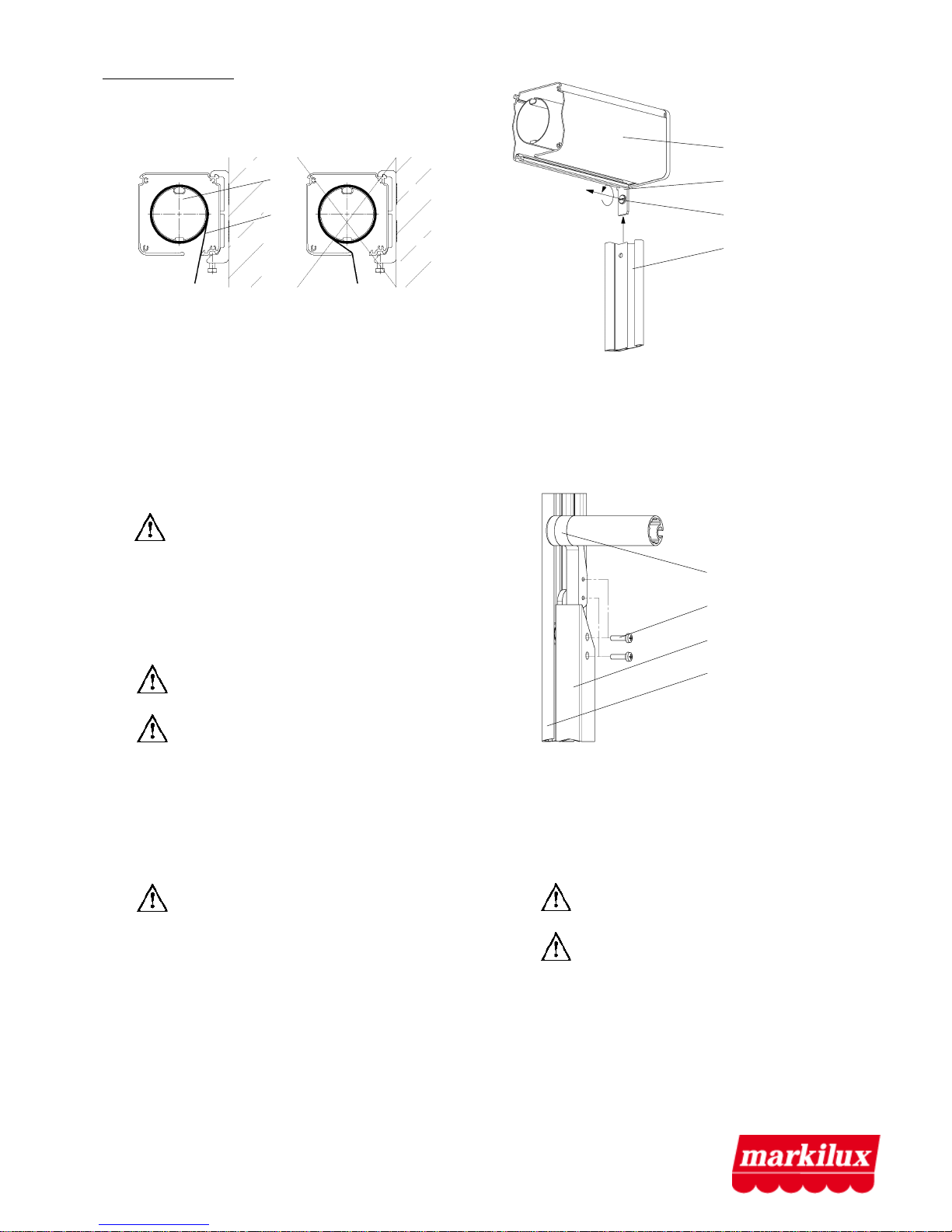
tional drillings have to be made laterally in the
rails.
There are grooves in the rails to make it easier for
the customer to make drillings in the same dis-
tances as the drillings already in place.
Mounting drillings in the angled guide rails for the
max. screw size for niche mounting drive and/or
motor:
Attention: It has to be observed for the niche
mount hat only countersunk-head screws that do
not protrude are used, as the the downpipe is
guided in he groove.
3. Motor connection
The lead-in for the motor and the control connec-
tion has to be installed and connected by an ap-
proved electrician (as per VDE 0100). The connec-
tion has to be executed acc. to the regulations of
the manufacturer of the motor/controller.
Modifications, especially concerning the motor, the
controller and the connecting supply lines require
our authorization.
Cable exit on motor driven units
Attention:
3.1 For the unmonitored operation of the electro-
motive powered mini-awning with automatic
control the following has to be observed:
If the mounting height of moveable parts of the
window awning to the circulation are is less
than 2.5 m, special safety measures have to be
taken in order to prevent possible injuries
(mech. shielding, overload protection, contact
strip, photocell, etc).
No persons and obstacles should be within the
extension and retraction range of the awning!
Special care has to be taken for accessible areas
in which children could be.
3.2 For the operation of a electromotive powered
mini-awning with manual switch the extension
and retraction motion has to be stoppable and
permanently controllable by the user, if the
awning is in an accessible area and the safety
distance of 2.5 m, described under point "3.1"
cannot be adhered to. In this case switch push
buttons have to be used permitting by simply
omitting the operation button thus enabling a
stop of the extension and retraction motion
(principle of dead man's switch).
3.3 The automatic operation of the awning must
not lead to falls of persons possibly working at
the facade. An overriding switching locking de-
vice or blocking barrier has to make impossible
any adjustment of the awning if there are works
taking place at the building facade.
Setting the motor end switch:
Attention: The built-in motor has a set end
stop both in the extension and retraction direction.
These settings were effected in the factory. They
always have to be checked on site, as the end stops
might have shifted e.g. through strong vibrations
during transport or the motor does not switch off
anymore. For any changes or corrections of these
settings please refer to the instructions of the
motor.
The installation and setting instructions are indi-
cated on the motor's power supply cable. When
setting remote-controlled motors please start with
point "factory"-programming of the instruction
manual!
Attention: The rolling up of the fabric on the
fabric roller from top during retraction could result
in damage to the awning fabric and the awning
frame. When setting the end positions of the motor
it is important to ensure that the fabric winds up as
shown during the retraction process:

4
1
2
Sense of rotation of the fabric roller during the
retraction process:
CORRECT! WRONG!
1 = fabric roller
2 = fabric
When the awning is extended, at least half a turn of
the fabric has to remain on the fabric roller as secu-
rity! Never set the end position of the motor in such
a way that the fabric unwinds completely.
We cannot assume any responsibility for damages
resulting from wrong settings.
4. Mounting / suspension of awning (single
unit)
4.1 emove protective cover and check individual
parts.
Attention: There is tension on the slide
mechanisms! Do not yet remove the tubular
foil.
4.2 Mark the position of the rails on the mounting
surface, mark drillings on the undersurface and
the angled guide rails (only for reveal mount-
ing) and make drillings.
Attention: Observe the drilling type for
niche mount.
Attention: The angled guide rails
have to be mounted parallel to each other and
at a right angle to the cassette (measure
drillings diagonally).
4.3 For units with interior operation:
Mark drillings for drive pin and console on the
drive side according to the supplied template
and drill hole.
Attention: The inside laying is pivoted for
tension-free connection with the drive rod..
adjustment range to horizontal level:
about 0° downwards
about 30° upwards
4.4 Before mounting the mini-awning it has to be
assembled partly:
Slide the angled guide rails into the provided
anchorages at the casing (lateral cover) and
unscrew the flat-head screw so that it.
4.5 Screw the mini-awning in its fixation points in
the angled guide rails to the undersurface.
4.6 Extend awning fabric and and fix downpipe
bracket to the slide mechanism. Afterwards re-
tract the awning fabric again until it is taut.
4.7 emove the foils from the slide mechanisms
and extend the mini-awning.
4.8 Fix the fabric guide tube to the slide mecha-
nism. For this the drop-arms have to be
pressed in direction of the rails so that there is
no tension on the fabric.
Attention: The awning fabric has to be
guided from behind the fabric guide tube..
Attention: The guide tube bracket with the
guide tube has to point in direction of the
fabric towards the back.
casing
lateral covers
flat-head screw
guide rail
downpipe bracket
oval-head screw M5
slide mechanism
angled guide rail

5
4.9 etract the mini-awning completely. Set the
stop strip in the tracks. When tightening the
screws ensure that the stop strip does not twist
in the track (press when tightening).
Attention: Ensure same position on
both sides of the rails. If required align the stop
strips should they have twisted during the
tightening process.
4.10 Extend the mini-awning completely and adjust
the stop strips if required. If required, the drive
end lock has to be adjusted in extension direc-
tion for manual-driven units.
stop strip
guide tube
guide tube bracket
slide mechanism
angled guide rail
Table of contents
Other Markilux Accessories manuals

Markilux
Markilux 1700 User manual

Markilux
Markilux 990 User manual

Markilux
Markilux markilux pergola User manual

Markilux
Markilux 790 Quick start guide

Markilux
Markilux 869 User manual

Markilux
Markilux 779 User manual

Markilux
Markilux Syncra uno User manual

Markilux
Markilux 710 User manual

Markilux
Markilux 990 User manual

Markilux
Markilux 8800 tracfix User manual