SENTRONIC M-SYSTEM Mini-M Series User manual

MODEL: M2AS1
Super-mini Signal Conditioners Mini-M Series
DC ALARM
(thumbwheel switch adjustment; single SPDT output)
Functions & Features
• Provides a SPDT relay output at a preset DC input level
• Thumbwheel switch setpoint adjustments
• Adjustable deadband
• Latching or non-latching output
• Relays energized or de-energized at tripped condition
• CE marking
Typical Applications
• Annunciator
• Various alarm applications
31
44
23 (.91)
76
(2.99)
124
(4.88)
mm (inch)
MODEL: M2AS1–[1][2][3][4]–[5][6]
ORDERING INFORMATION
• Code number: M2AS1-[1][2][3][4]-[5][6]
Specify a code from below for each [1] through [6].
(e.g. M2AS1-6111-M2/CE/Q)
• Specify the specification for option code /Q
(e.g. /C01/S01)
[1] INPUT
Current
A: 4 – 20 mA DC (Input resistance 250 Ω)
Voltage
4: 0 – 10 V DC (Input resistance 1 MΩ min.)
5: 0 – 5 V DC (Input resistance 1 MΩ min.)
6: 1 – 5 V DC (Input resistance 1 MΩ min.)
[2] ALARM OUTPUT
1: Hi (coil energized at alarm)
2: Hi (coil de-energized at alarm)
3: Lo (coil energized at alarm)
4: Lo (coil de-energized at alarm)
[3] ON DELAY TIME
1: 0.05 second
2: 0.1 second
3: 0.2 second
4: 0.5 second
5: 1 second
6: 2 seconds
7: 5 seconds
8: 10 seconds
[4] POWER ON DELAY TIME
1: 1 second
2 : 2 seconds
3 : 3 seconds
4 : 4 seconds
[5] POWER INPUT
AC Power
M2: 100 – 240 V AC (Operational voltage range 85 – 264 V,
47 – 66 Hz)
DC Power
R: 24 V DC
(Operational voltage range 24 V ±10 %, ripple 10 %p-p max.)
R2: 11 – 27 V DC
(Operational voltage range 11 – 27 V, ripple 10 %p-p max.)
(Select ‘/N’ for ‘Standards & Approvals’ code.)
P: 110 V DC
(Operational voltage range 85 – 150 V, ripple 10 %p-p max.)
[6] OPTIONS (multiple selections)
STANDARDS & APPROVALS (must be specified)
/N: Without CE
/CE: CE marking
OTHER OPTIONS
blank: none
/Q: Option other than the above (specify the specification)
SPECIFICATIONS OF OPTION: Q (multiple selections)
COATING (For the detail, refer to M-System's web site.)
/C01: Silicone coating
/C02: Polyurethane coating
/C03: Rubber coating
TERMINAL SCREW MATERIAL
/S01: Stainless steel
GENERAL SPECIFICATIONS
Construction: Plug-in
Connection: M3 screw terminals (torque 0.8 N·m)
Housing material: Flame-resistant resin (black)
Isolation: Input to output to power
Rugghölzli 2
CH - 5453 Busslingen Tel.+41 (0)56 222 38 18
Fax +41 (0)56 222 10 12 mailbox@sentronic.com
www.sentronic.com
Produkte, Support und Service
SENTRONICAG
MODEL: M2AS1
Overrange input: -14 to +113.5 %
When the relay’s untripped point relative to the preset
alarm setpoint and deadband is out of this range, the relay
remains latched.
Setpoint adjustments: Thumbwheel switches (front);
0 – 99 % independently; 1 % increments
Hysteresis (deadband): Thumbwheel switches (front);
1 – 99 % independently; 1 % increments
(latching output when set to 00)
Front LED: Red light turns on when the coil is energized.
Reset input: Latched output reset with the front control
button or remotely via base socket terminals.
INPUT SPECIFICATIONS
• DC Current:
Shunt resistor attached to the input terminals (0.5 W)
• Reset Contact Input
ON resistance: ≤ 1 kΩ
OFF resistance: ≥ 50 kΩ
OUTPUT SPECIFICATIONS
• Relay Contact:
120 V AC @5 A (cos ø = 1)
240 V AC @2.5 A (cos ø = 1)
30 V DC @5 A (resistive load)
Maximum switching voltage: 250 V AC or 120 V DC
Maximum switching power: 600 VA or 150 W
Minimum load: 5 V DC @10 mA
Mechanical life: 5 × 10⁷ cycles
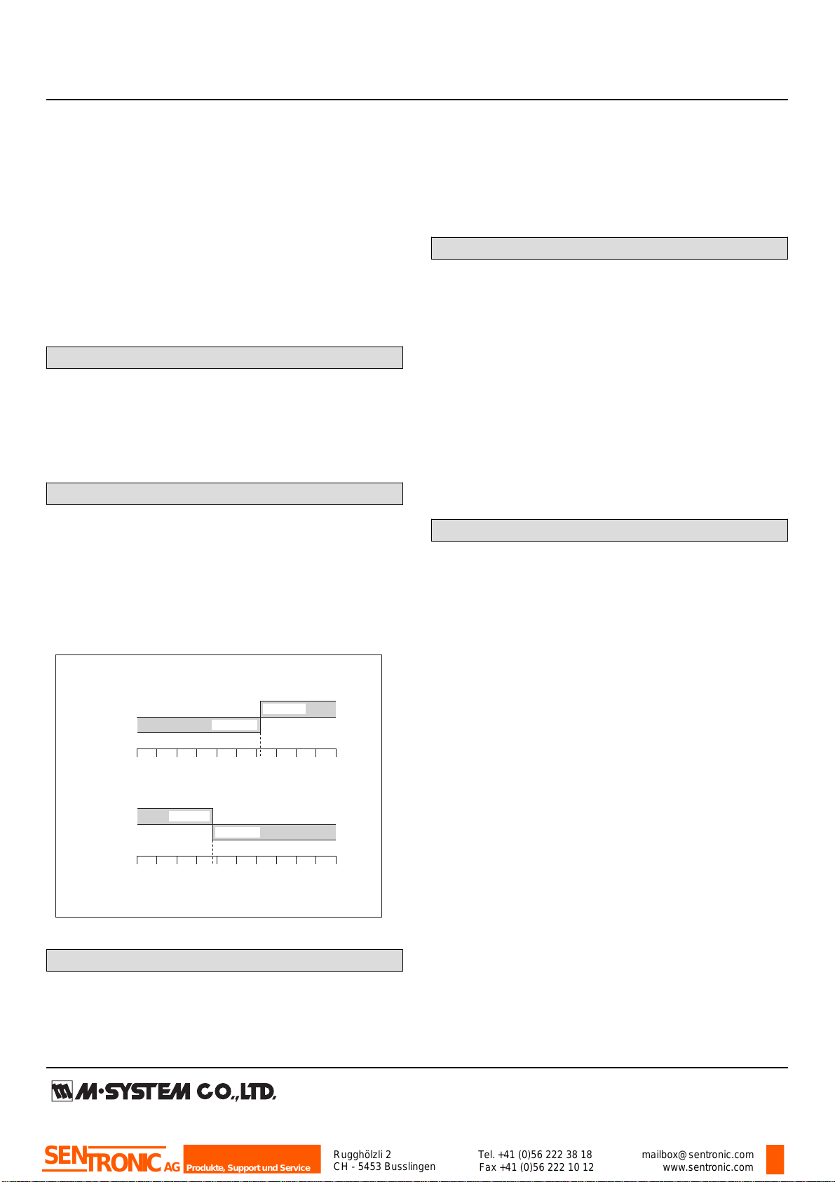
Alarm Trip Operation Terminal No. in parentheses
Trip Operation in Power Failure: Terminals 8 – 12 turn on.
0 50 100
Input
(%) ▲
Setpoint
Output (8–12)ON (8–9)ON
0 50 100▲
Input
(%) Setpoint
(8–9)ON
Output (8–12)ON
• Output Code : 1, 4
• Output Code : 2, 3
INSTALLATION
Power Consumption
•AC Power input:
Approx. 3 VA at 100 V
Approx. 4 VA at 200 V
Approx. 5 VA at 264 V
•DC Power input: Approx. 3 W
Operating temperature: -5 to +55°C (23 to 131°F)
Operating humidity: 30 to 90 %RH (non-condensing)
Mounting: Surface or DIN rail
Installation Base (model: M2BS) is not adaptable.
Weight: 150 g (0.33 lbs)
PERFORMANCE in percentage of span
Setpoint accuracy: ±0.5 %
Deadband setpoint accuracy: ± 0.5 %
Delay time (response time with 90 % setpoint for a step
input 0 – 100 %)
Codes 1, 2: Rating ±25 msec.
Codes 3 to 8: Rating ±20 %
Power ON timer: Rating ±0.5 sec.
Trip point repeatability: ±0.05 %
Temp. coefficient: ±0.015 %/°C (±0.008 %/°F)
Line voltage effect: ±0.1 % over voltage range
Insulation resistance: ≥ 100 MΩ with 500 V DC
Dielectric strength: 2000 V AC @1 minute (input to output
to power to ground)
STANDARDS & APPROVALS
CE conformity:
EMC Directive (2004/108/EC)
EN 61000-6-4 (EMI)
EN 61000-6-2 (EMS)
Low Voltage Directive (2006/95/EC)
EN 61010-1
Installation Category II
Pollution Degree 2
Max. operating voltage 300 V
Input or output to power: Reinforced insulation
Input to output: Basic insulation
Rugghölzli 2
CH - 5453 Busslingen Tel.+41 (0)56 222 38 18
Fax +41 (0)56 222 10 12 mailbox@sentronic.com
www.sentronic.com
Produkte, Support und Service
SENTRONICAG

MODEL: M2AS1
EXTERNAL VIEW
Output Setpoint Adj.
Deadband Adj.
Output Monitor LED
Reset Control
9 9
9 9
DIMENSIONS unit: mm (inch)
5
9
21.5 (.85)
70.5 (2.78)
86.7 (3.41)7.3 (.29) 15 (.59)
6 (.23)
59 (2.32)
DIN RAIL
35mm wide
[4 (.16)]
8–M3
SCREW
72 (2.83)
23 (.91)
2–4.2x5
(.17x.20)
MTG HOLE
6 (.24) deep
116.7 (4.59)
• When mounting, no extra space is needed between units.
14
8
12
14 13
4 (.16)
TERMINAL ASSIGNMENTS unit: mm (inch)
58
9
12
14 13
INPUT RESISTOR
(model: REM2)
19 (.75)
Input shunt resistor attached
for current input.
14
Rugghölzli 2
CH - 5453 Busslingen Tel.+41 (0)56 222 38 18
Fax +41 (0)56 222 10 12 mailbox@sentronic.com
www.sentronic.com
Produkte, Support und Service
SENTRONICAG

MODEL: M2AS1
SCHEMATIC CIRCUITRY & CONNECTION DIAGRAM
Base Socket
5
Comparator
1Low Drift
Amplifier
4
Converter
Converter
9
12
8
OUTPUT
*Input shunt resistor attached for current input.
9 9
THUMBWHEEL
SWITCHES
THUMBWHEEL
SWITCHES
9 9
N.C.
N.O.
COM
+
–
*
INPUT
RESET
R
U(+)
V(–) POWER
13
14
LOAD
Inductive
Load (Coil)
Varistor or CR Circuit
■ Relay Protection
• AC Powered
• DC Powered
LOAD
Inductive
Load (Coil)
Diode, Varistor or
CR Circuit
RESET
CONTROL
Ry
FUNCTIONS
■HIGH ALARM: When the signal input exceeds
the preset setpoint, the relay provides a tripped
condition.
• Hi Alarm
Input
t
Setpoint
Deadband
Bold Line
Thin Line : Alarm Tripped
: Alarm Untripped
• Lo Alarm
Input
t
Setpoint
Deadband
Bold Line
Thin Line : Alarm Tripped
: Alarm Untripped
Input TD T<TD
TD
t
Setpoint
Bold Line: Coil Energized
• ON Delay Time (TD) with Hi Alarm
• Power ON Delay Time (TDP) with Hi Alarm
Input TDP
Power ON
t
Setpoint
Bold Line: Coil Energized
Deadband
Input
t
Setpoint
Reset Command
• Latching Output with Hi Alarm
■LOW ALARM: When the signal input goes below
the preset setpoint, the relay provides a tripped
condition
■ON DELAY TIME: The relay status does not change
until after the preset ON Delay Time (TD) once the
signal input goes across the threshold.
■POWER ON DELAY TIME: The relay does not provide
a tripped condition for a duration of the preset Power
ON Delay Time (TDP) after the power supply is turned
on, even when the signal input is in an alarm range.
■ LATCHING OUTPUT: The relay does not return to an
untripped condition once the signal input goes across
the threshold, unless:
(1) the Reset control button is pressed,
(2) the Reset input terminal is closed, or
(3) the power supply is removed.
Rugghölzli 2
CH - 5453 Busslingen Tel.+41 (0)56 222 38 18
Fax +41 (0)56 222 10 12 mailbox@sentronic.com
www.sentronic.com
Produkte, Support und Service
SENTRONICAG

MODEL: M2AS1
Specifications are subject to change without notice.
Rugghölzli 2
CH - 5453 Busslingen Tel.+41 (0)56 222 38 18
Fax +41 (0)56 222 10 12 mailbox@sentronic.com
www.sentronic.com
Produkte, Support und Service
SENTRONICAG

M2AS1
P. 1 / 2EM-5064 Rev.1
DC ALARM
(thumbwheel switch adjustment; single SPDT output) MODEL M2AS1
INSTRUCTION MANUAL
BEFORE USE ....
Thank you for choosing M-System. Before use, please check
contents of the package you received as outlined below.
If you have any problems or questions with the product,
please contact M-System’s Sales Office or representatives.
■ PACKAGE INCLUDES:
Signal conditioner (body + base socket + input resistor)
..... (1)
Input resistor is provided only with current input type.
■ MODEL NO.
Confirm Model No. marking on the product to be exactly
what you ordered.
■ INSTRUCTION MANUAL
This manual describes necessary points of caution when
you use this product, including installation, connection and
basic maintenance procedures.
POINTS OF CAUTION
■ CONFORMITY WITH EC DIRECTIVES
• This equipment is suitable for use in a Pollution Degree
2 environment and in Installation Category II, with the
maximum operating voltage of 300V.
Basic insulation is maintained between signal input and
output. Prior to installation, check that the insulation
class of this unit satisfies the system requirements.
• Altitude up to 2000 meters
•The equipment must be mounted inside a panel.
• The equipment must be installed such that appropriate
clearance and creepage distances are maintained to con-
form to CE requirements. Failure to observe these re-
quirements may invalidate the CE conformance.
■ POWER INPUT RATING & OPERATIONAL RANGE
• Locate the power input rating marked on the product and
confirm its operational range as indicated below:
100 – 240V AC rating: 85 – 264V, 47 – 66 Hz, approx. 3 – 5VA
24V DC rating: 24V ±10%, approx. 3W
11 – 27V DC rating: 11 – 27V, approx. 3W
110V DC rating: 85 – 150V, approx. 3W
■ GENERAL PRECAUTIONS
• Before you remove the unit from its base socket or mount
it, turn off the power supply and input signal for safety.
• DO NOT apply excessive pressure on the thumbwheel
switches.
■ ENVIRONMENT
•Indoor use
•When heavy dust or metal particles are present in the air,
install the unit inside proper housing with sufficient ven-
tilation.
• Do not install the unit where it is subjected to continuous
vibration. Do not subject the unit to physical impact.
• Environmental temperature must be within -5 to +55°C
(23 to 131°F) with relative humidity within 30 to 90% RH
in order to ensure adequate life span and operation.
• Be sure that the ventilation slits are not covered with ca-
bles, etc.
■ WIRING
•Do not install cables (power supply, input and output)
close to noise sources (relay drive cable, high frequency
line, etc.).
• Do not bind these cables together with those in which
noises are present. Do not install them in the same duct.
■ AND ....
•The unit is designed to function as soon as power is sup-
plied, however, a warm up for 10 minutes is required for
satisfying complete performance described in the data
sheet.
COMPONENT IDENTIFICATION
INSTALLATION
Loosen the fixing screw at the front of the unit in order to
separate the body from the base socket.
■ DIN RAIL MOUNTING
Set the base socket so that
its DIN rail adaptor is at
the bottom. Position the
upper hook at the rear side
of base socket on the DIN
rail and push in the lower.
When removing the socket,
push down the DIN rail
adaptor utilizing a minus
screwdriver and pull.
■ WALL MOUNTING
Refer to “EXTERNAL DI-
MENSIONS.”
TERMINAL CONNECTIONS
Connect the unit as in the diagram below or refer to the con-
nection diagram on the side of the unit.
When an input resistor is provided with the module, attach
it together with input wiring to the input screw terminals.
31
44
Body Base Socket
Connection
Diagram
Specifications
Fixing Screw
DIN Rail
35mm wide
Spring Loaded
DIN Rail Adaptor
Input Resistor
9
8
12 N.C.
OUTPUT
N.O.
COM
*Input shunt resistor attached for current input.
U(+)
V(–) POWER
13
14
5
1
4
+
–
*
INPUT
RESET
R
Rugghölzli 2
CH - 5453 Busslingen Tel.+41 (0)56 222 38 18
Fax +41 (0)56 222 10 12 mailbox@sentronic.com
www.sentronic.com
Produkte, Support und Service
SENTRONICAG

M2AS1
CHECKING
1) Terminal wiring: Check that all cables are correctly con-
nected according to the connection diagram.
2) Power input voltage: Check voltage across the terminal
13 – 14 with a multimeter.
3) Input: Check that the input signal is within 0 – 100% of
the full-scale.
4) Alarm operations: Check the alarm operations referring
to the figure below.
5) Output load: Check that the output load is 250V AC/
600VA or 30V DC/150W at the maximum. For maximum
relay life with inductive loads, external protection is rec-
ommended.
SETPOINT ADJUSTMENTS
Turn the thumbwheel switch-
es until desired figures in per-
cent are shown. The output
operation is set to “Latching”
when the Deadband Adj. is set
to 00. Monitor LED turns on
when the coil is energized ([in-
put] > [setpoint] for Codes 1 or
4, [input] < [setpoint] for Codes 2 or 3).
MAINTENANCE
Regular calibration procedure is explained below:
■ CALIBRATION
Warm up the unit for at least 10 minutes.
• Hi Alarm
Increase the input signal from a value lower than the set-
point and check that the relay trips at the setpoint.
• Lo Alarm
Decrease the input signal from a value higher than the set-
point and check that the relay trips at the setpoint.
When the setpoints are shifted, contact M-System’s Sales
Office or representatives.
EXTERNAL DIMENSIONS unit: mm (inch)
5
9
21.5(.85)
70.5 (2.78)
86.7 (3.41)7.3(.29) 15(.59)
6(.23)
59 (2.32)
DIN RAIL
35mm wide
[4 (.16)]
8–M3
SCREW
72 (2.83)
23 (.91)
2–4.2x5
(.17x.20)
MTG HOLE
6 (.24) deep
116.7 (4.59)
• When mounting, no extra space is needed between units.
14
8
12
14 13
4 (.16)
■
TERMINAL ASSIGNMENTS
58
9
12
14 13
INPUT RESISTOR
(model: REM2)
19 (.75)
Input shunt resistor attached
for current input.
14
Alarm Trip Operation Terminal No. in parentheses
Trip Operation in Power Failure: Terminals 8 – 12 turn on.
0 50 100
Input
(%) ▲
Setpoint
Output (8–12)ON (8–9)ON
0 50 100▲
Input
(%) Setpoint
(8–9)ON
Output (8–12)ON
• Output Code : 1, 4
• Output Code : 2, 3
9 9
9 9
Output
Setpoint Adj.
Deadband Adj.
Output
Monitor LED
Reset Control
Rugghölzli 2
CH - 5453 Busslingen Tel.+41 (0)56 222 38 18
Fax +41 (0)56 222 10 12 mailbox@sentronic.com
www.sentronic.com
Produkte, Support und Service
SENTRONICAG
Other manuals for M-SYSTEM Mini-M Series
2
This manual suits for next models
1
Table of contents
Other SENTRONIC Test Equipment manuals


