SENTRONIC M5VF Series User manual

MODEL: M5VF
Super-mini Terminal Block Signal Conditioners M5-UNIT
SIGNAL TRANSMITTER
(high speed response)
Functions & Features
• Converts a DC input into an isolated DC signal
• Ultra-high speed response 150 μsec.
• High-density mounting
• Power LED
• CE marking for 24 V DC power
25 (.98)
97
(3.82)
41 (1.61)
mm (inch)
MODEL: M5VF-[1][2]-[3][4]
ORDERING INFORMATION
Specify a code from below for each [1] through [4].
• Code number: M5VF-[1][2]-[3][4]
(e.g. M5VF-4W4W-R/Q)
Specify variables.
• Special input and output ranges (For codes Z & 0)
• Specify the specification for option code /Q
(e.g. /C01 )
[1] INPUT
Current
A: 4 – 20 mA DC (Input resistance 249 Ω)
B: 2 – 10 mA DC (Input resistance 499 Ω)
C: 1 – 5 mA DC (Input resistance 1000 Ω)
D: 0 – 20 mA DC (Input resistance 49.9 Ω)
E: 0 – 16 mA DC (Input resistance 61.9 Ω)
F: 0 – 10 mA DC (Input resistance 100 Ω)
G: 0 – 1 mA DC (Input resistance 1000 Ω)
H: 10 – 50 mA DC (Input resistance 20 Ω)
Z: Specify current (See INPUT SPECIFICATIONS)
Voltage
3: 0 – 1 V DC (Input resistance 1 MΩ min.)
4: 0 – 10 V DC (Input resistance 1 MΩ min.)
5: 0 – 5 V DC (Input resistance 1 MΩ min.)
6: 1 – 5 V DC (Input resistance 1 MΩ min.)
4W: -10 – +10 V DC (Input resistance 1 MΩ min.)
5W: -5 – +5 V DC (Input resistance 1 MΩ min.)
0: Specify voltage (See INPUT SPECIFICATIONS)
[2] OUTPUT
Current
A: 4 – 20 mA DC (Load resistance 550 Ω max.)
Z: Specify current (See OUTPUT SPECIFICATIONS)
(Not selectable with the power input code M)
Voltage
4: 0 – 10 V DC (Load resistance 1000 Ω min.)
5: 0 – 5 V DC (Load resistance 500 Ω min.)
6: 1 – 5 V DC (Load resistance 500 Ω min.)
4W: -10 – +10 V DC (Load resistance 8000 Ω min.)
(For the input suffix codes 4W and 5W only)
5W: -5 – +5 V DC (Load resistance 4000 Ω min.)
(For the input suffix codes 4W and 5W only)
0: Specify voltage (See OUTPUT SPECIFICATIONS)
(Not selectable with the power input code M)
[3] POWER INPUT
AC Power
M: 85 – 264 V AC (Operational voltage range 85 – 264 V,
47 –66 Hz)
(CE not available)
DC Power
R: 24 V DC
(Operational voltage range 24 V ±10 %, ripple 10 %p-p max.)
[4] OPTIONS
blank: none
/Q: With options (specify the specification)
SPECIFICATIONS OF OPTION: Q
COATING (For the detail, refer to M-System's web site.)
/C01: Silicone coating
/C02: Polyurethane coating
/C03: Rubber coating
GENERAL SPECIFICATIONS
Construction: Terminal block
Connection: M3.5 screw terminals (torque 0.8 N·m)
Screw terminal: Nickel-plated steel
Housing material: Flame-resistant resin (black)
Isolation: Input to output to power
Zero adjustment: -2 to +2 % (front)
(±1 % with the input suffix codes 4W and 5W selected)
Span adjustment: 98 to 102 % (front)
(99 to 101 % with the input suffix codes 4W and 5W
selected.)
Power LED: Green light turns on when the power is supplied.
Rugghölzli 2
CH - 5453 Busslingen Tel.+41 (0)56 222 38 18
Fax +41 (0)56 222 10 12 mailbox@sentronic.com
www.sentronic.com
Produkte, Support und Service
SENTRONICAG

MODEL: M5VF
INPUT SPECIFICATIONS
■ DC Current: Input resistor incorporated
Specify input resistance value for code Z.
(R ≤ 0.125 W ÷ [F.S. Current]2)
■ DC Voltage: -30 – +30 V DC
Minimum span: 1 V
Offset: Max. 1.5 times span
Input resistance: 1 MΩ min.
(10 kΩ min. at power loss)
OUTPUT SPECIFICATIONS
■ DC Current: 0 – 20 mA DC
Minimum span: 1 mA
Offset: Max. 1.5 times span
Load resistance: Output drive 11 V max.; 9 V max. for the
full-scale output < 3 mA
■ DC Voltage: 0 – 10 V DC
Minimum span: 1 V
Offset: Max. 1.5 times span
Load resistance: Output drive 10 mA max.; at ≥ 1 V
INSTALLATION
Power Consumption
•AC:
Approx. 2 VA at 100 V
Approx. 2 VA at 200 V
Approx. 3 VA at 264 V
•DC: Approx. 2 W
Operating temperature: -5 to +55°C (23 to 131°F)
Operating humidity: 0 to 90 %RH (non-condensing)
Mounting: DIN rail
Weight: 80 g (2.8 oz)
PERFORMANCE in percentage of span
Accuracy: ±0.1 %
Temp. coefficient: ±0.015 %/°C (±0.008 %/°F)
±0.02 %/°C (±0.01 %/°F) with AC power
Response time: ≤ 150 μsec. (0 – 90 %)
Line voltage effect: ±0.1 % over voltage range
Insulation resistance: ≥ 100 MΩ with 500 V DC
Dielectric strength (input to output to power to ground)
DC powered: 2000 V AC @1 minute
AC powered: 1500 V AC @1 minute
STANDARDS & APPROVALS
CE conformity:
EMC Directive (2004/108/EC)
EMI EN 61000-6-4: 2007
EMS EN 61000-6-2: 2005
Rugghölzli 2
CH - 5453 Busslingen Tel.+41 (0)56 222 38 18
Fax +41 (0)56 222 10 12 mailbox@sentronic.com
www.sentronic.com
Produkte, Support und Service
SENTRONICAG

MODEL: M5VF
FRONT VIEW
Span Adj.
Power LED
Zero Adj.
1 2
3 4
5 6
7 8
EXTERNAL DIMENSIONS & TERMINAL ASSIGNMENTS unit: mm (inch)
94 (3.70)3 (.12)
25 (.98) 41 (1.61) [3.3 (.13)]
• When mounting, no extra space is needed between units.
DIN RAIL
35mm wide
8–M3.5 SCREW
7.3 (.29)
35.4 (1.39)
1 2
3 4
5 6
7 8
SCHEMATIC CIRCUITRY & CONNECTION DIAGRAM
Isolation
SZ
Low Drift
Amplifier Output
Driver
3
4
1
2
*Input shunt resistor incorporated for current input.
*+
–OUTPUT
5
6
8
7
+
–
SIGNAL SOURCE
The M5VF, by its fast-response feature, is not designed to eliminate noise present in the input signal.
Use a shielded twisted-pair cable for preventing noise entering through the input wiring.
POWER LED
U(+)
V(–) POWER
Specifications are subject to change without notice.
Rugghölzli 2
CH - 5453 Busslingen Tel.+41 (0)56 222 38 18
Fax +41 (0)56 222 10 12 mailbox@sentronic.com
www.sentronic.com
Produkte, Support und Service
SENTRONICAG
M5VF
P. 1 / 2EM-2464 Rev.5
SIGNAL TRANSMITTER
(high speed response) MODEL M5VF
INSTRUCTION MANUAL
BEFORE USE ....
Thank you for choosing M-System. Before use, please check
contents of the package you received as outlined below.
If you have any problems or questions with the product,
please contact M-System’s Sales Office or representatives.
■ PACKAGE INCLUDES:
Signal conditioner......................................................... (1)
■ MODEL NO.
Confirm Model No. marking on the product to be exactly
what you ordered.
■ INSTRUCTION MANUAL
This manual describes necessary points of caution when
you use this product, including installation, connection and
basic maintenance procedures.
POINTS OF CAUTION
■ CONFORMITY WITH EC DIRECTIVES
• The equipment must be mounted inside a panel.
• Insert a noise filter for the power source, input and out-
put connected to the unit. COSEL Noise Filter Model
NAC-06-472, TDK Noise Filter Model ZCAT 3035-1330 or
equivalent is recommended.
•The actual installation environments such as panel con-
figurations, connected devices, connected wires, may af-
fect the protection level of this unit when it is integrated
in a panel system. The user may have to review the CE
requirements in regard to the whole system and employ
additional protective measures to ensure the CE conform-
ity.
■ POWER INPUT RATING & OPERATIONAL RANGE
•Locate the power input rating marked on the product and
confirm its operational range as indicated below:
85 – 264V AC rating: 85 – 264V, 47 – 66 Hz, approx. 2 – 3VA
24V DC rating: 24V ±10%, approx. 2W
■ GENERAL PRECAUTIONS
• Before you remove the unit or mount it, turn off the power
supply and input signal for safety.
■ ENVIRONMENT
•Indoor use
• When heavy dust or metal particles are present in the air,
install the unit inside proper housing with sufficient ven-
tilation.
• Do not install the unit where it is subjected to continuous
vibration. Do not subject the unit to physical impact.
• Environmental temperature must be within -5 to +55°C
(23 to 131°F) with relative humidity within 0 to 90% RH
in order to ensure adequate life span and operation.
■ WIRING
•Do not install cables (power supply, input and output)
close to noise sources (relay drive cable, high frequency
line, etc.).
• Do not bind these cables together with those in which
noises are present. Do not install them in the same duct.
• Install lightning surge protectors for those wires connect-
ed to remote locations. For 24V DC power supply line,
choose a surge protector with its maximum surge voltage
40V or less between lines. Recommended M-System mod-
el: MDP-D24.
■ AND ....
•The unit is designed to function as soon as power is sup-
plied, however, a warm up for 20 minutes is required for
satisfying complete performance described in the data
sheet.
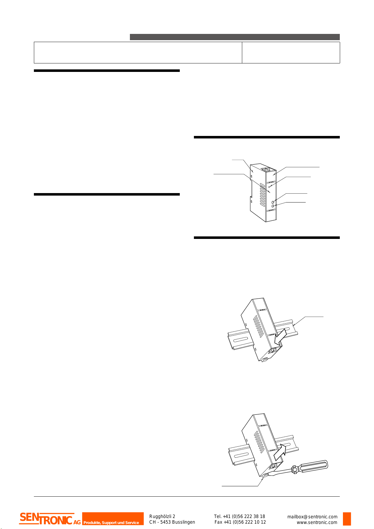
COMPONENT IDENTIFICATION
INSTALLATION
Set the unit so that its DIN rail adapter is at the bottom.
■ MOUNTING THE UNIT ON A DIN RAIL
A) Hang the upper hook at the rear side of unit on the DIN
rail.
B) Push in the lower in keeping pressing the unit to the
DIN rail.
■ REMOVING THE UNIT
A) Push down the DIN rail adaptor using a minus screw-
driver.
B) Pull out the lower part of the unit.
C) Remove the upper part from the DIN rail.
Power LED
Terminal Cover
Zero Adj.
Span Adj.
Body
Spec. Marking
A
B
DIN Rail
A
C
B
Spring Loaded
DIN Rail Adaptor
Rugghölzli 2
CH - 5453 Busslingen Tel.+41 (0)56 222 38 18
Fax +41 (0)56 222 10 12 mailbox@sentronic.com
www.sentronic.com
Produkte, Support und Service
SENTRONICAG

M5VF
P. 2 / 2EM-2464 Rev.5
M-SYSTEM WARRANTY
M-System warrants such new M-System product which it manufactures to be free from defects in materials and workmanship
during the 36-month period following the date that such product was originally purchased if such product has been used under
normal operating conditions and properly maintained, M-System’s sole liability, and purchaser’s exclusive remedies, under this
warranty are, at M-System’s option, the repair, replacement or refund of the purchase price of any M-System product which is
defective under the terms of this warranty. To submit a claim under this warranty, the purchaser must return, at its expense, the
defective M-System product to the below address together with a copy of its original sales invoice.
THIS IS THE ONLY WARRANTY APPLICABLE TO M-SYSTEM PRODUCT AND IS IN LIEU OF ALL OTHER WARRANTIES,
EXPRESS OR IMPLIED, INCLUDING ANY IMPLIED WARRANTIES OF MERCHANTABILITY OR FITNESS FOR A PARTICU-
LAR PURPOSE. M-SYSTEM SHALL HAVE NO LIABILITY FOR CONSEQUENTIAL, INCIDENTAL OR SPECIAL DAMAGES
OF ANY KIND WHATSOEVER.
M-System Co., Ltd., 5-2-55, Minamitsumori, Nishinari-ku, Osaka 557-0063 JAPAN, Phone: (06) 6659-8201, Fax: (06) 6659-
8510, E-mail: [email protected]
TERMINAL CONNECTIONS
Connect the unit as in the diagram below or refer to the con-
nection diagram on the front of the unit.
■ EXTERNAL DIMENSIONS unit: mm (inch)
■ CONNECTION DIAGRAM
94 (3.70)3 (.12)
25 (.98) 41 (1.61) [3.3 (.13)]
• When mounting, no extra space is needed between units.
35.4 (1.39)
DIN RAIL
35mm wide
8–M3.5 SCREW
7.3 (.29)
1 2
3 4
5 6
7 8
CHECKING
1) Terminal wiring: Check that all cables are correctly con-
nected according to the connection diagram.
2) Power input voltage: Check voltage across the terminal
7 – 8 with a multimeter.
3) Input: Check that the input signal is within 0 – 100% of
the full-scale.
4) Output: Check that the load resistance meets the de-
scribed specifications.
ADJUSTMENT PROCEDURE
This unit is calibrated at the factory to meet the ordered
specifications, therefore you usually do not need any cali-
bration.
For matching the signal to a receiving instrument or in case
of regular calibration, adjust the output as explained in the
following.
■ HOW TO CALIBRATE THE OUTPUT SIGNAL
Use a signal source and measuring instruments of sufficient
accuracy level. Turn the power supply on and warm up for
more than 20 minutes.
1) ZERO: Apply 0% input and adjust output to 0%.
2) SPAN: Apply 100% input and adjust output to 100%.
3) Check ZERO adjustment again with 0% input.
4) When ZERO value is changed, repeat the above proce-
dure 1) – 3).
MAINTENANCE
Regular calibration procedure is explained below:
■ CALIBRATION
Warm up the unit for at least 20 minutes. Apply 0%, 25%,
50%, 75% and 100% input signal. Check that the output
signal for the respective input signal remains within accu-
racy described in the data sheet. When the output is out of
tolerance, recalibrate the unit according to the “ADJUST-
MENT PROCEDURE” explained earlier.
+
–OUTPUT
5
6
7
8
3
4
+
–
The M5VF, by its fast-response feature, is not designed
to eliminate noise present in the input signal.
Use a shielded twisted-pair cable for preventing noise
entering through the input wiring.
SIGNAL
SOURCE
U(+)
V(–) POWER
Rugghölzli 2
CH - 5453 Busslingen Tel.+41 (0)56 222 38 18
Fax +41 (0)56 222 10 12 mailbox@sentronic.com
www.sentronic.com
Produkte, Support und Service
SENTRONICAG
Table of contents
Other SENTRONIC Test Equipment manuals


Popular Test Equipment manuals by other brands


Bacharach
Bacharach Fyrite Tech 50 Operating and maintenance instructions

Sterling Power Products
Sterling Power Products DBT125 manual

Desco
Desco 19780 Technical bulletin

GE
GE Multilin EPM 7000 quick start guide

Perel
Perel EFL20S user manual

Tektronix
Tektronix TDS3000C Series Compliance and Safety Instructions