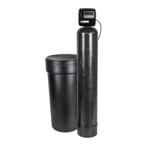
SENTRY II 950SM Series User manual

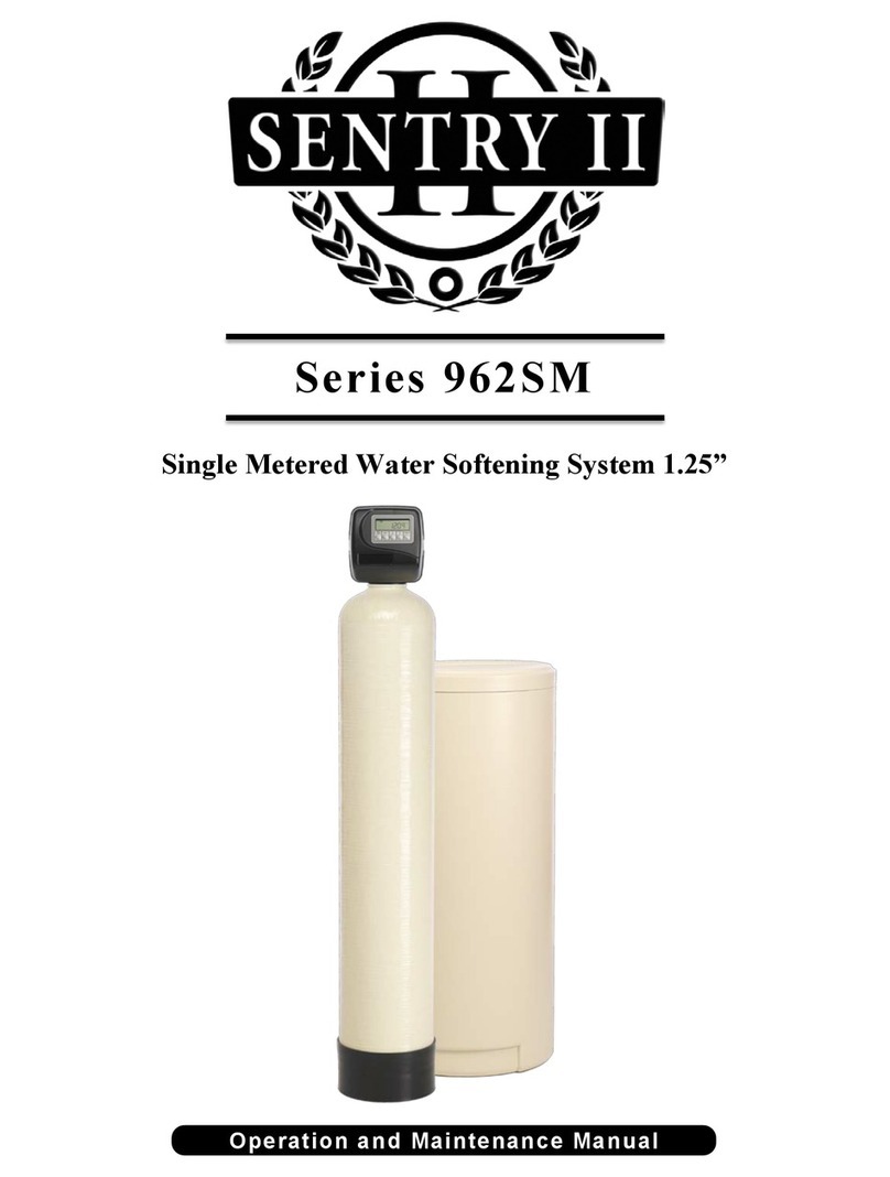
Single Metered Water Softening System
Operation and Maintenance Manual
Series 950SM

2

3
Table of Contents
System Specifications and Warnings .............................................................................. 4
Installation Instructions .................................................................................................... 5
Start-Up Instructions ....................................................................................................... 11
Series 950 Control Valve Programming ........................................................................ 13
Parts Breakdown
Front Cover and Drive Assembly ........................................................................... 18
Main Body Internal Parts ........................................................................................ 19
Injector Housing Assembly .................................................................................... 20
Meter Assembly ....................................................................................................... 21
Brine Elbow Refill Flow Assembly and Refill Port Plug ....................................... 22
Drain Line Assembly ............................................................................................... 23
1” Drain Assembly ................................................................................................... 24
Bypass Breakdown ................................................................................................. 25
Bypass Valve Operation ......................................................................................... 26
Installation Fitting Assemblies ............................................................................... 27
Brine Tank Assembly .............................................................................................. 29
System Specifications ............................................................................................ 30
Service Instructions ........................................................................................................ 32
Troubleshooting for the Control Valve .......................................................................... 37

4
System Specifications
Water pressure: 40 psi minimum 100 psi Maximum
Water Temperature: 40°F to 110°F
Electrical Requirements:
Supply Voltage: 120V
Supply Frequency: 60Hz
Output Voltage: 12V AC
Output Current: Maximum 3.0 Amps
Water Meter:
Pipe Size: 1-1/4”
Accuracy: ± 5%
Minimum Flow : 0.25 GPM
Control Valve to Tank Connection: 2.5”-8UN
Control Valve Distributor Pipe Connection: 1.05”
Circuit Board Memory: NonVolatile EEPROM (Electrical Erasable Programmable Read Only Memory)
Compatible with the following typical concentrations of regenerant chemicals: Sodium Chloride, Potassium
Chloride, Potassium Permangenate, Sodium Bisulfite, Chlorine and Chloramines
Warnings
The control valve and fittings are not designed to support the weight of the system or the
plumbing.
Do not use Vaseline, oils, other hydrocarbon lubricants or spray silicone anywhere. A
silicone lubricant may be used on black O-rings.
Hydrocarbons such as kerosene, benzene, gasoline, etc., may damage products that
contain O-rings or plastic components. Exposure to such hydrocarbons may cause the
products to leak. Do not use the product(s) contained in this document on water supplies
that contain hydrocarbons such as kerosene, benzene, gasoline, etc.
The water meter should not be used as the primary monitoring device for critical or health
effect applications.
Do not use pipe dope or other sealants on threads. Teflon tape is recommended to be
used on all threads. Use of pipe dope may break down the plastics in the control valve.
System Specifications and Warnings

5
Installation Instructions
Installation
Instructions

6

7
Installation Instructions
Pre-Installation Checklist
1. A standard electrical outlet (120V/160Hz) must be located within 12’ of installation
site.
2. A functioning floor drain, washer sand pipe or suitable location for waste water
discharge must be located within 20’ of installation site.
a. All plumbing should be done in accordance with local plumbing codes. The pipe size for the drain line
should be a minimum of 1/2”. Backwash flow rates in excess of 7 gpm or length in excess of 20’
require 3/4” drain line.
3. A working pressure reducing valve must be installed on the inlet water line that
supplies the water softener.
4. (Note: The warranty is void if the system is exposed to water pressure in
excess of 100 psi.)
5. The temperature at the location of the water softener system must never be below
40˚F.
Installation
1. Floor Space: Make sure the floor space that has been selected to install the
water softener is clean and on a level surface.
2. Leveling the Salt Container: If the floor beneath the salt container is not level,
do not use shims or spacers to level the salt container. A platform that supports
the entire bottom surface of the salt container must be used.
3. What to Bypass: A typical installation would include bypassing the outside hose
bibs. The cold water feeding the kitchen sink may or may not be bypassed
depending upon preference.
4. Connection Kit: The standard connection kit supplied with the water softener will
be a 3/4" brass sweat connection kit. (See Figure 1) Other connection kits are
available. This kit will consist of the following:

8
Installation Instructions
5. Plumbing Preparations: Unscrew the two plastic nuts (#1) and pull on the two
brass connectors (#4) to remove them from the bypass assembly. Next remove the
white plastic rings (#2) and the O-rings. (#3) See Figure 1
•Solder at least 6” of pipe to the brass connectors before reassembly.
(See Figure 2)
•After soldering is complete, cool the pipe and connectors. Slide the
plastic nuts (#1) over the brass connectors (#4). Place the white plastic
split rings (#2) into the grooves closest to the end of the brass
connectors (#4). Reassembly the connection kit onto the bypass
assembly.
Warning: When assembling the installation-fitting package (inlet and outlet), connect the fitting to the
plumbing system first and then attach the nut, split ring and O-ring. Heat from soldering or sol- vent cements
may damage the nut, split ring or o- ring. Solder joints should be cool and solvent cements should be set
before installing the nut, split ring and O-ring. Avoid getting primer and solvent cement on any part of the O-
rings, split rings, bypass valve or control valve.
6. Plumbing: When connecting the water softener to the existing plumbing, make
sure the inlet water is connected to the inlet of the softener. Arrows on the valve body
indicate direction of flow. Make sure the bypass valves are in the correct position See
Figure 3.
Note: All plumbing should be done in accordance with local plumbing codes.
Warning: The control valve, fittings and/or bypass are designed to accommodate minor plumbing
mis-alignments but are not designed to support the weight of a system or the plumbing.
Figure 1
Figure 2
Figure 3

9
Installation Instructions
7. Locate Polytube Insert:Now that the water softener is connected to the existing
plumbing, the drain line may be connected. First, locate and remove the polytube
insert (#2) from the gray cable on the left side of the control valve.
8. Connecting the Drain Line: Slide plastic nut (#3) over the permanent drain
tubing and place the polytube insert (#2) into the end of the drain tubing. Insert the
drain tubing into the drain elbow fitting (#4) and tighten plastic nut (#3) hand-tight
plus 1/2 turn with pliers. Caution: Do Not Over-tighten. (See Figure 4)
9. Drain Line Specs: If the distance from the water softener to the drain is greater
than 20’ the drain line size must be increased to 3/4”. The threads on the drain elbow
fitting are 3/4” male NPT and can be used in lieu of the 1/2” plastic nut and insert. If
the drain line must run overhead, the maximum height of the drain line should not
exceed 8’ above the top of the water softener.
10. Air Gap: The drain line must have an approved air gap to prevent the possibility
of a cross connection to the sewer. (See Figure 5)
Figure 4
Figure 5

10
Installation Instructions
11. Connecting the overflow line: The brine overflow fitting is located on the
outside of the salt container approximately 12” down from the top. Connect 1/2” drain
tubing to the overflow fitting and run it to the nearest floor drain. This line is a gravity
flow line and cannot be run overhead or cannot connect to a drain that is higher than
the overflow fitting.
12. Connecting the brine line (Figure 6): A 3/8” brine line approximately 4’ long is
attached to the salt container and is supplied with the tube insert in the end of the
brine line. Insert the brine line into the brine fitting (#3) firmly making sure that it is
fully seated. You will notice some resistance when the brine line encounters the o-
ring inside of the brine elbow. Caution: If the brine line is not inserted completely, the
tubing will leak from this point. Verify that there are no leaks during the start-up
procedure.
The water softener is equipped with a 15-foot power cord with built-in transformer. Plug the
power cord into a standard (120V 60Hz) electrical outlet. It will take approximately 10
seconds before you will see the display (this is normal). The water softener is now ready to
be programmed.
Figure 6

11
Start-Up
To begin, place the bypass in the position shown in Figure 1.
Place the softener in the Backwash cycle.
•To place the softener in the Backwash cycle press
and hold the REGEN button (approx. 6 seconds) until
the control valve initiates a regeneration cycle. The
softener is now in the Backwash cycle. An initial burst
of air will be released to the drain. Leave the unit in
the Backwash cycle until the water running to the
drain runs clear.
•Press the REGEN button to advance the controller to
the next cycle. The softener is now in the Brine/Slow
Rinse cycle.
•When the timer begins countdown press the REGEN
button to advance the controller to the next cycle. The
softener is now in the 2nd Backwash cycle.
•When the timer begins countdown press the REGEN
button to advance the controller to the next cycle. The
softener is now in the Fast Rinse cycle. Leave the
unit in the Fast Rinse cycle for at least five minutes.
•While the system is in the Fast Rinse Cycle, manually
fill the brine tank with fresh water until there is
approximately 2” of water above the false bottom.
•Press the REGEN button to advance the controller to
the next cycle. The softener is now in the Brine Tank
Fill cycle. Leave the unit in the Brine Tank Fill cycle
for at least one minute. This will ensure that there is
no air trapped in the brine tubing and valve.
IMPORTANT:
After the unit has filled for approximately 1
minute, raise the float to shut off the flow of water
and then check the float valve, brine tubing and
connections for leaks.
•Press the REGEN button to advance the controller to
the home position.
•Salt may be placed in the unit at this time.
To complete the Start-up procedure place bypass in the
position shown in Figure 2
Start-Up Instructions
Figure 1
Figure 2

12

13
Control Valve Programming
Series 950
Control Valve Programming

14
Control Valve Programming
Programming
Step 1
Step 2
Step 3 - Day Override:This setting should be set to 15. Press NEXT to go to Step 4.
Step 4 - Regeneration Time: The system regenerates at 2:00 AM. This setting is adjustable. No
water should be used during regeneration. (Typically this is the middle of the night.)
Press NEXT to exit programming.
Step 2
Step 3
The control valve has been pre-programmed from the factory with the correct regeneration cycle
program and cycle times. The gallon capacity between regeneration can be changed by adjusting
the water hardness.
Step 1 - Press the NEXT and the UP Arrow buttons at the same time and hold for 2 seconds.
Step 2 - Raw Water Hardness:Adjust to the correct hardness by pressing the UP or DOWN arrow
button. Default setting 20 grains per gallon. Press NEXT to go to Step 3.

15
Screen 3
Step 1
Control Valve Programming
Normal Operating Screens
Screen 1
Screen 2
Step 1 - Press SET CLOCK
Step 2 - Current Time of Day - Hours: Adjust to the correct hour by pressing the UP or
DOWN arrow button. Press NEXT to go to Step 3.
Step 3 - Current Time of Day - Minutes: Adjust to the correct minutes by pressing the up or
down arrow button. Press NEXT to return to the normal operating screen.
The time of day should only need to be set after initial installation or after an extended power outage. If an
extended power outage has occurred, the time of day will flash indicating that it needs to be set.
Set the Time of Day
Step 2
Step 3
During normal operation one of three screens can be displayed.
Pressing the NEXT button alternates between these screens.
Screen 1 - Current Time of Day
Screen 2 - Current Flow Rate in Gallons per Minute
Screen 3 - Capacity Remaining in Gallons

16

17
Parts Breakdown
Parts
Breakdown

18
Drawing
No.
Part No. Description Quantity
1 V3175CC-01 Front Cover Assembly 1
2 V3107-01 Drive Motor 1
3 V3106-01 Drive Bracket and Spring Clip 1
4 V3108CC Circuit Board 1
5 V3110 Drive Reducing Gear 3
6 V3109 Drive Gear Cover 1
Not Shown V3186 Transformer 110VAC-12VAC 1
Correct
battery
orientation.
Battery
replacement is 3
volt lithium coin
cell type 2032.
When replacing the battery,
align positives and push
down to fully seat.
Parts Breakdown
Front Cover and Drive Assembly

19
Parts Breakdown
Main Body Internal Parts

20
Parts Breakdown
Injector Housing Assembly
Drawing
No.
Part No. Description Quantity
1 V3176 Injector Cap 1
2 V3152 O-Ring Injector Cap 1
3 V3177-01 Injector Screen 1
4
V3010-1A
V3010-1B
V3010-1C
V3010-1D
V3010-1E
V3010-1F
V3010-1G
V3010-1H
V3010-1I
V3010-1J
V3010-1K
V3010-1Z
Injector Assembly – A Black
Injector Assembly – B Brown
Injector Assembly – C Violet
Injector Assembly – D Red
Injector Assembly – E White
Injector Assembly – F Blue
Injector Assembly – G Yellow
Injector Assembly – H Green
Injector Assembly – I Orange
Injector Assembly – J Light Blue
Injector Assembly – K Light Green
Injector Assembly – Z Plug
1
The size of your system will determine which injector assembly will be needed.
Table of contents
Other SENTRY II Water Dispenser manuals

SENTRY II
SENTRY II 952TA Series User manual

SENTRY II
SENTRY II 960SM Series User manual

SENTRY II
SENTRY II 954SM Series User manual

SENTRY II
SENTRY II 960 Series User manual

SENTRY II
SENTRY II 972SM Series User manual

SENTRY II
SENTRY II 930TA Series User manual

SENTRY II
SENTRY II 962SM Series User manual

SENTRY II
SENTRY II 959TA14 Series User manual

SENTRY II
SENTRY II 940ST Series User manual
Popular Water Dispenser manuals by other brands
Zass
Zass ZWD 20 C instruction manual

abc
abc Fleck 5600SXT manual

SYR
SYR LEX Plus 10 Connect Instructions for use and maintenance

PURE
PURE Marvella RO instruction manual

WaterLogic
WaterLogic WL400 Series Operating, installation and service manual

Elkay
Elkay FLEXI-GUARD EFW Deluxe Installation, care & use manual