Fleck 9100SXT Meter Installation manual

INSTALLATION & START-UP
INSTRUCTIONS
FLECK 9100SXT METER
TWIN ALTERNATING
WATER SOFTENER SYSTEMS

Preface:
Thank you for your purchase of a new Water Softener with Fleck 9100SXT Meter from
QualityWaterForLess.com! We have put together these instructions as reference, and to
be used as general installation guidelines. It is always recommended that a licensed
plumber perform all installation work according to all local codes. We at
QualityWaterForLess.com cannot assume responsibility for improper installation,
application, injury, or damage as a result of improper installation.
Pre-Installation Guidelines:
Before assembly of your new system, be sure that the following conditions have been met
for placement of your system:
•Level, firm surface, such as concrete, on which to place the softener tank and salt
tank (as known as a ‘brine’ tank)
•Nearby floor drain or standpipe to connect to the softener for use during each
regeneration
•Un-switched power source, standard US plug, 120v 60hz (the softener system
includes a 5ft. power cord and plug)
•Access to the water main coming into your home. You will need to install the
softener at this point to assure that water for the home is going through the
system.
Placing and Filling the Tank:
•Choose the final location for your water softener tank, and place the tank upright
and level on the surface.
•Filling the tank may be necessary on some systems. Your tanks may have also
come prefilled, and in this case you only need to unscrew the protective cap as
shown below in Figure 1 and move on to the next section.
FIGURE 1
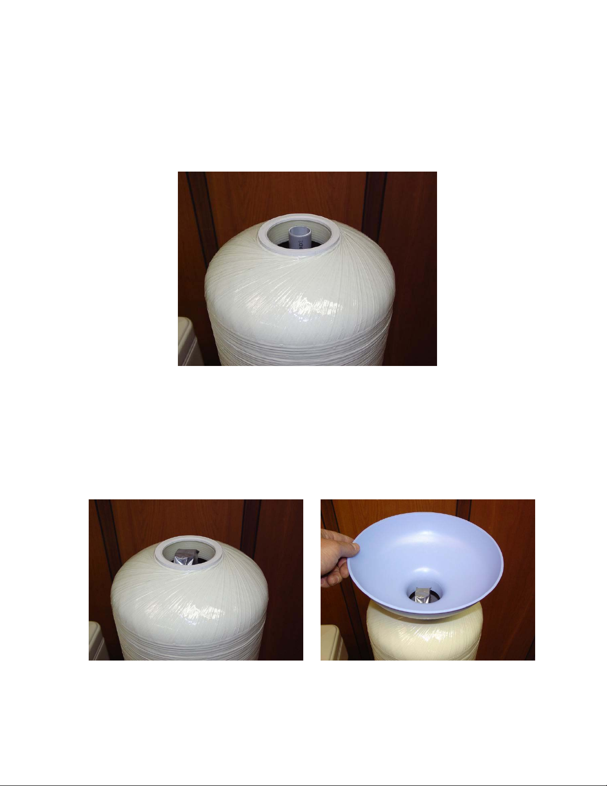
•If your tank is not filled, please follow the additional instructions below.
•First, place the riser tube into the tank as shown in Figure 2. NOTE: Please be
sure that the riser tube seats into the bottom of the tank, and that the top of
the riser tube is FLUSH with the top of the tank lip.
FIGURE 2
•Before filling the tank, place a piece of duct tape over the top of the riser to
prevent resin from dropping down inside the riser tube as shown in Figure 3.
•Place the included filling funnel over the top the tank as shown in Figure 4, and
prepare to fill the tank. Since the 9100SXT is a twin system, please be sure to fill
½ of the included resin for each tank. If your softener system came with
Gravel, please pour this amount into the tank FIRST, then pour in the
included resin media afterwards. Please note that you must split the amount of
supplied resin and gravel EQUALLY for EACH tank shipped!
FIGURE 3 FIGURE 4
•Remove the filling funnel and duct tape and repeat for the second tank. After
the second tank is filled, go on to the next section
Installing the Fleck 9100SXT Meter Control Valve:
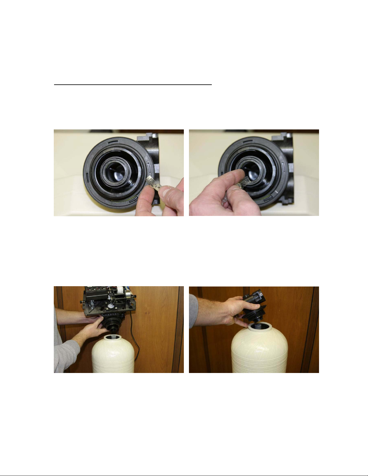
•Using the included silicone lubricant packet, lubricate the inner and outer o-
rings on the bottom of the Fleck 9100SXT Meter Valve as shown in Figures 5
& 6 below. Please repeat this for the main valve, and the secondary portion, as
shown below.
FIGURE 5 FIGURE 6
•Next, place the Fleck 9100SXT Meter Valve and secondary portion onto the
top of each tank, being sure that the riser tube fits into the central o-ring on
each, as shown in figures 7 & 8 below. Hand tighten each to the tank snugly
by hand only. NOTE: Do not use Teflon tape or pipe dope on the valve or
tank threads.
FIGURE 7 FIGURE 8
•Locate the yoke and/or bypass valve assembly that was shipped with your
system. Also, disassemble the plumbing adaptor clips as shown in Figures 8 &
9 on the following page.
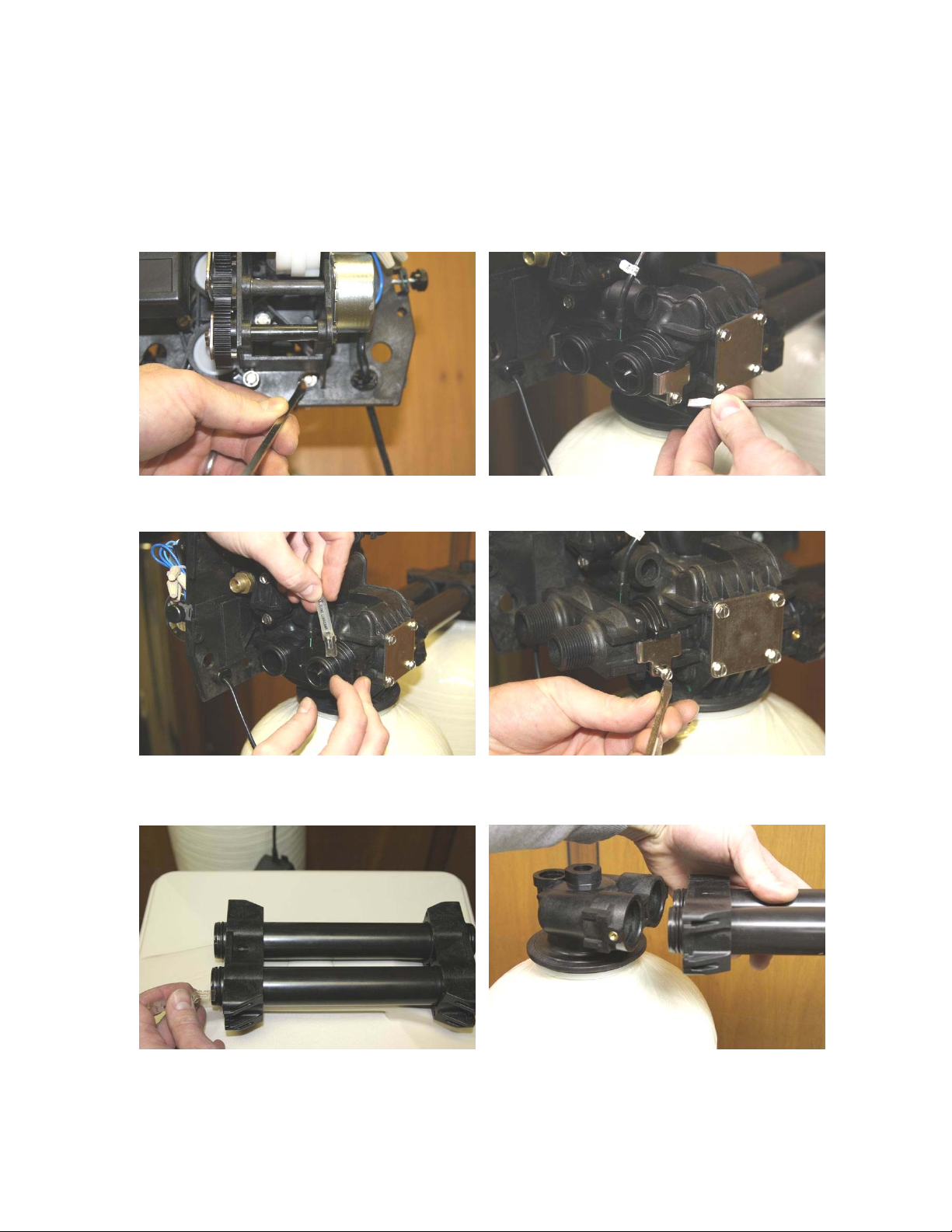
•Using the included silicone lubricant packet, lubricate the o-rings on the
9100SXT Valve meter assembly as shown in figure 10 below.
•Finally, push the yoke or bypass valve snugly to the back of the 9100SXT
valve. Use the clips & screws to secure each side of the yoke or bypass valve
as shown in Figure 11 below.
FIGURE 8 FIGURE 9
FIGURE 10 FIGURE 11
FIGURE 12 FIGURE 13

•Locate the included interconnect adaptor and lubricate all four o-rings as shown in
figure 12 on the preceding page.
•Push the interconnect assembly onto the secondary portion as shown in figure 13
on the preceding page.
•Use the included screws and clips to secure both sides of this connection as shown
in figure 14 below.
•Push the interconnect assembly onto the secondary portion as shown in figure 15
below.
•Use the included screws and clips to secure both sides of this connection as shown
in figure 16 below.
FIGURE 14 FIGURE 15
FIGURE 16
Plumbing your Fleck 9100SXT Meter:
•Before beginning your installation, please first familiarize yourself with the “IN”
and “OUT” on the Fleck 9100SXT Meter Valve. In order to prevent damage to
your home and to the softener system, install the softener according to the
“IN” and “OUT” arrows on the softener valve!
•Find the main shut-off valve for your house and turn it to the “OFF” position. If
you have a private well, this valve should be near your well pressure tank. If you
have a city water supply, your valve should be near your water meter.

•Depressurize and drain your home of water by turning on all faucets and fixtures
in your home, including those outside.
•Pick your installation point, and cut a section of pipe out to run to and from your
softener. NOTE: In many cases, it is preferred to keep outside lines
UNSOFTENED. If you wish to keep your outside lines unsoftened, you must
plumb “Bypass” lines to run hard water to these fixtures.
•Using soldered copper, PVC plastic pipe, or flexible connections, plumb the
system according to all local plumbing codes. NOTE: If using copper pipe,
please pre-fabricate at least a 12” section of pipe for the “IN” and “OUT”
bound lines and use a wet rag on the lines being soldered to prevent heat
damage during soldering!
•Once all connections have been made, place the system into bypass by either
using your existing 3-valve bypass (if ordered with a Yoke adaptor), or by
switching your included bypass to “IN BYPASS” position.
•Next, gradually open your main valve and allow all air in your plumbing lines to
escape slowly. Also, you may turn off all outside and inside faucets and fixtures.
•Check for leaks at your plumbing site for signs of slow drips, and rectify if
necessary.
•Please DO NOT position the bypass valve to “IN SERVICE” at this time, as the
installation is completed yet! NOTE: Please take this opportunity to check and
re-check the “IN” and “OUT” to make sure that they are correct!
Making the Brine Tank Connection:
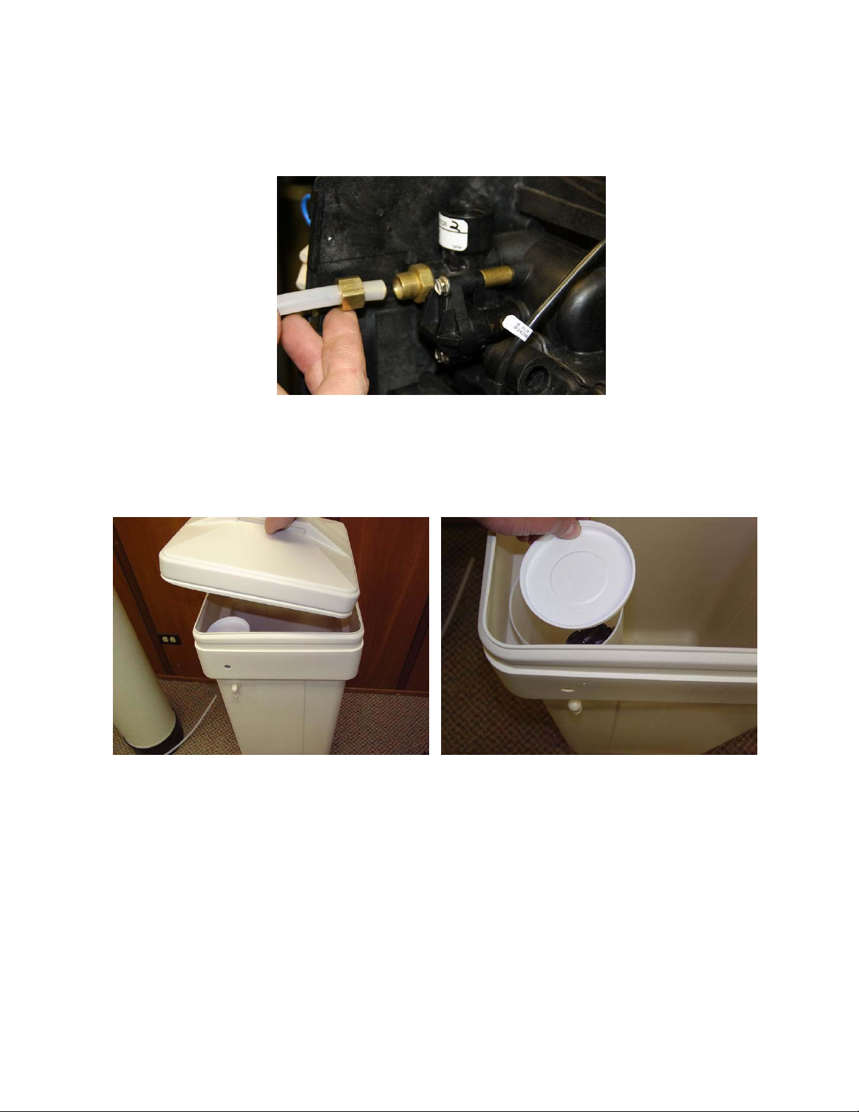
•Locate the included Brine Fitting Assembly and section of brine tubing as shown
in figure 17 below.
•Onto one side of the included Brine Tubing, assemble the Brine Nut Assembly as
shown in Figure 18 below.
FIGURE 17 FIGURE 18
•Tighten the nut to the Brine Fitting Assembly using until snugly tightened in
place. Be careful not to over tighten, as you may sever the brine line tubing. See
figure 19 below.
FIGURE 19
•Locate the included brine tank, and remove the brine tank cover shown on the
following page in Figure 20.
•Next, locate the brine well, and remove the cap as shown in Figure 21 on the
following page.
FIGURE 20 FIGURE 21
•Pull the 2310 brine float assembly out of the brine well and disassemble the
retaining nut as shown in Figure 22 on the following page.
•Next, assemble the 2310 brine float assembly to the brine well through the pre-
drilled hole and hand-tighten as shown in figure 23 on the following page.

FIGURE 22 FIGURE 23
•Take the other end of your brine line tube and insert the tube through the small
hole drilled through the brine tank, and brine well. Loosely unscrew the hex nut
on the 2310 brine float assembly. Insert the tubing end firmly into the hex nut on
the 2310 brine float assembly.
•Next back-off the hex nut and ferrule assembly so they are securely onto the
tubing as shown in Figure 24 below. NOTE: Please be sure to assemble the nut
in the fashion described to prevent system malfunction and possible brine
tank overflow!
•Hand-tighten the hex nut snugly onto the 2310 brine float assembly as shown in
Figure 25 below.
FIGURE 24 FIGURE 25
•Finally, use ½” I.D. tubing to connect the drain bard fitting on the brine tank to a
floor drain as shown in Figure 26 on the following page. NOTE: This is not
necessary as the 2310 assembly is designed to prevent an overflow situation, ,
but is a good and recommended precaution for a proper installation.
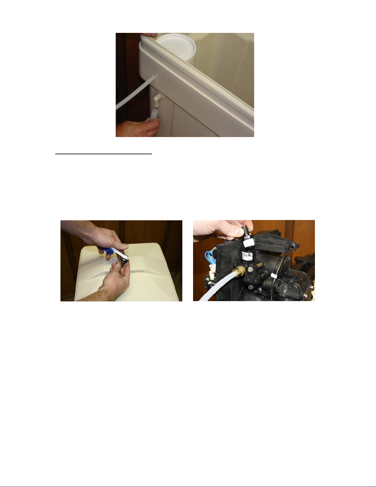
FIGURE 26
.
Making the Drain Connection:
•Locate the included Use Teflon tape to wrap the threading as shown in figure 28
below.
•Install the drain barb assembly included with your shipment to the Fleck
9100SXT Meter Valve by screwing the fitting using a wrench snugly into the
threads as shown in Figure 28 below. Please use caution not to over tighten this
fitting.
FIGURE 26 FIGURE 27
•Next, assemble your ½” I.D. drain line to the drain barb as shown in Figure 28 on
the following page. Be sure to use rigid wall ½” I.D. tubing that will not flatten
•Wrap electrical tape over the drain tubing to prevent a tubing split, and clamp the
tubing securely into place with the included blue clamp as shown in Figure 29 on
the following page.

FIGURE 28 FIGURE 29
•Connect the other end of this drain line tubing SECURELY to a standpipe or
drain in accordance with all local plumbing codes. NOTE: Be sure that the
drain line is securely in place before the use of the water softener system.
When the system regenerates, there will be increased flow via this tubing,
which may cause the tubing to become loose.
Programming the Fleck 9100SXT Meter Valve:
•Before start-up a few simple steps must be followed to program the Fleck
9100SXT Meter Valve.
•It will be important to know what your water Hardness and Iron is before doing
this programming procedure. If you do not know your water hardness, or if you
are unsure, you may wish to have it tested by sending us a sample for testing, or
by taking a sample to a local pool supply, or hardware store.
•Your Hardness test results may indicate “Grains”, “PPM”, or “mg/L”. It is
important to note that PPM and mg/L are the same measure and both figures can
be treated interchangeably. If you get a hardness figure in PPM or mg/L, please
divide this number by 17.1 to get Grains. Ex: If your hardness is measured at
300 PPM, your Grains are 300 / 17.1 = 18 Grains.
•Your Iron results should be measured in either “PPM” or “mg/L”. Add your level
of iron multiplied by 5. Add this number to your hardness level. This final figure
will be your Total Hardness Level that we will program into your softener system.
•To begin programming, first plug in your 9100SXT Valve to a nearby wall outlet.
The system will illuminate 4 digits. The system will show the time of day, the
current tank in service, and the amount of gallons remaining. This display will
switch between these valves about every 10 seconds.
•Access the timer control by loosening the cover thumbscrews as shown in figures
30 and 31 on the following page.
•Set the time on the system to 12:01 PM by pressing either the “UP” or “DOWN”
arrow as shown in figure 32 on the following page. You may hold the button to
allow the time to scroll faster.
•Once the time display is set to 12:01 PM, press the “extra cycle” button once as
shown in figure 33 on the following page.

FIGURE 30 FIGURE 31
FIGURE 32 FIGURE 33
•To enter master programming mode, press the “UP” and “DOWN” buttons
TOGETHER and HOLD for 5 seconds, and then release the buttons, as shown in
figure 34 below.
•The display should now show “DF / GAL” as shown in figure 35 below. (This
indicates U.S. Operation Mode - Gallons) Do not change this value, and press
the “Extra Cycle Button” once to continue.
FIGURE 34 FIGURE 35
•The display should now show “VT / St1b”as shown in figure 36 on the following
page. (This indicates Valve Type 9100 Mode) Do not change this value, and
press the “Extra Cycle Button” once to continue.
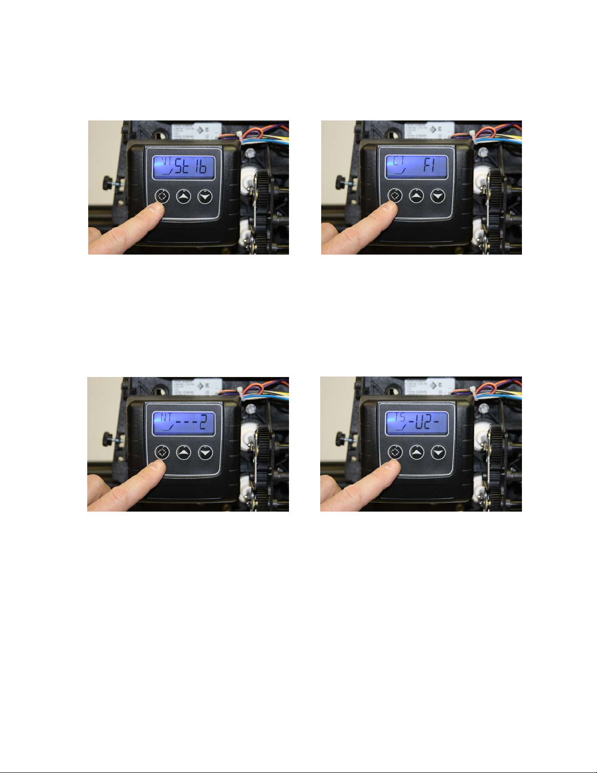
•The display should now show “CT / Fl” as shown in figure 37. (This indicates
Control Type METER IMMEDIATE Format) Do not change this value, and
press the “Extra Cycle Button” once to continue.
FIGURE 36 FIGURE 37
•The display should now show “NT / - - - 2” as shown in figure 38 below. (This
indicates Number of Tanks is Dual) Do not change this value, and press the
“Extra Cycle Button” once to continue.
•The display should now show “TS / - U 1 -” or “TS / - U 2 -” as shown in figure
39 below. (This indicates which tank is currently in service) Do not change this
value, and press the “Extra Cycle Button” once to continue.
FIGURE 38 FIGURE 39
•The display should now show “C / 24.0” as shown in figure 40 on the following
page. (This indicates the Capacity is 32,000 grains) Use the “UP” or “DOWN”
button to change this value to the size of your system, and press the “Extra
Cycle Button” once to continue when finished.
•The display should now show “H / 20” as shown in figure 41 on the following
page. (This indicates the Hardness is 20 grains) Use the “UP” or “DOWN”
button to change this value to the total hardness of you water (as calculated
on page 10), and press the “Extra Cycle Button” once to continue when
finished.
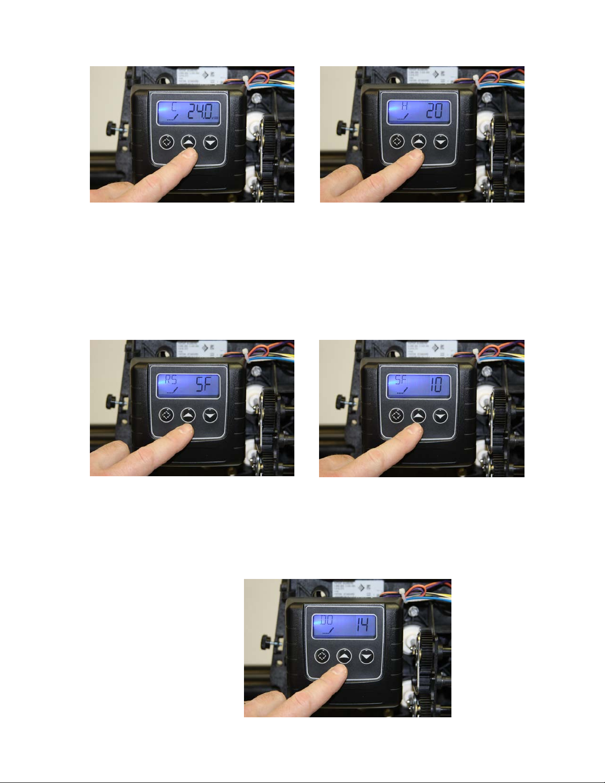
FIGURE 40 FIGURE 41
•The display should now show “RS / SF” as shown in figure 42 below. (This
indicates Reserve Selection is Safety Factor percentage) Do not change this
value, and press the “Extra Cycle Button” once to continue.
•The display should now show “SF / 20” as shown in figure 43 below. (This
indicates the Safety Factor is 20 percent) Use the “UP” or “DOWN” button to
change this value to “10”, and press the “Extra Cycle Button” once to
continue when finished.
FIGURE 42 FIGURE 43
•The display should now show “DO / 14” as shown in figure 44 below. (This
indicates the Day Override is 14 days – the system will regenerate on the 14th day
if the meter does not otherwise automatically initiate a regeneration based on
usage.) Do not change this value, and press the “Extra Cycle Button” once to
continue.
FIGURE 44
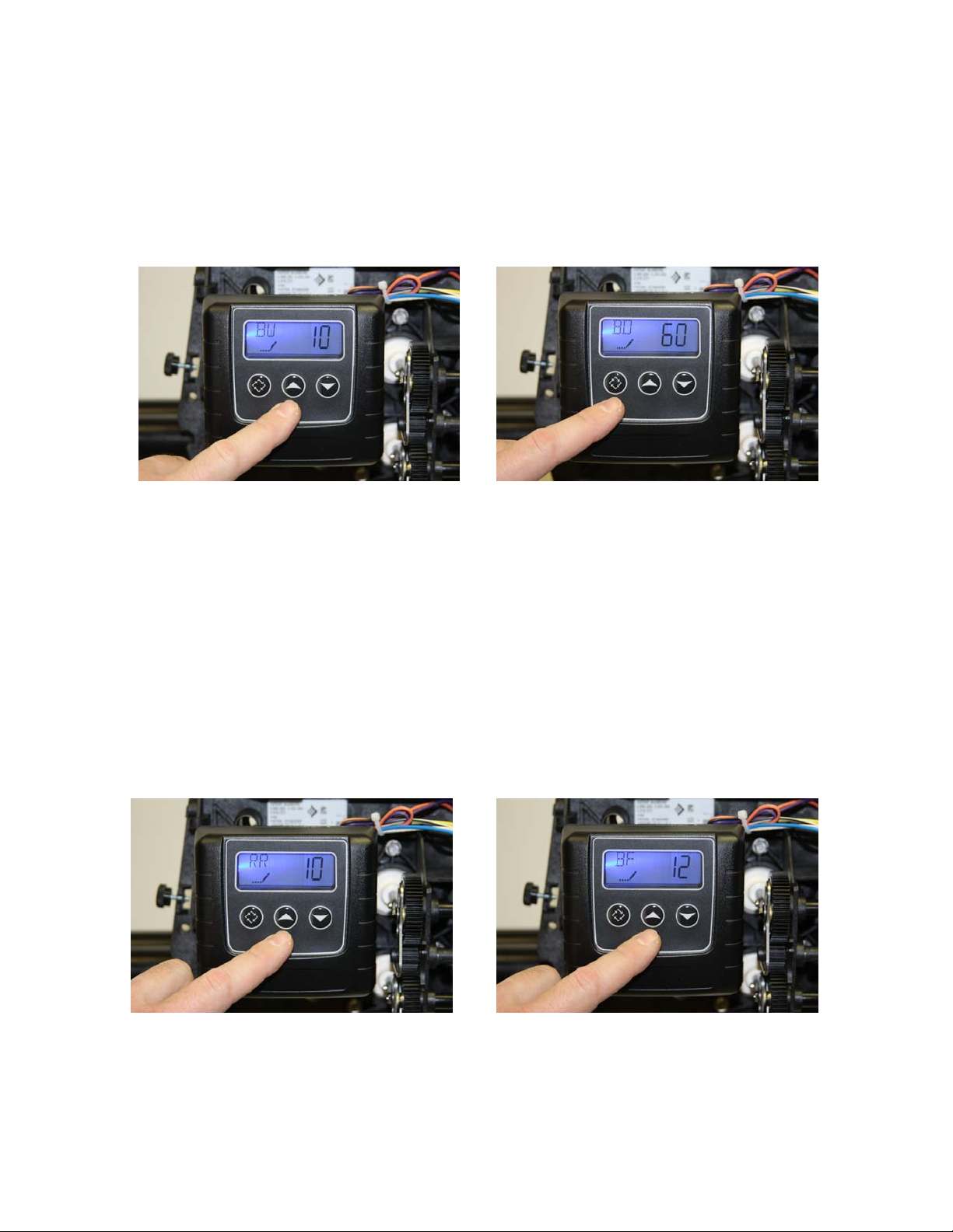
•The display should now show “BW / 10” as shown in figure 45 below. (This
indicates Backwash Time is 10 minutes in length) Do not change this value, and
press the “Extra Cycle Button” once to continue.
•The display should now show “BD / 60” as shown in figure 46 below. (This
indicates Brine Draw Time is 60 minutes) Do not change this value, and press
the “Extra Cycle Button” once to continue.
FIGURE 45 FIGURE 46
•The display may now show “RR / 10” as shown in figure 47 below. (This
indicates Rapid Rinse Time is 10 minutes) Do not change this value, and press
the “Extra Cycle Button” once to continue – if this value is different, use the
“UP” or “DOWN” buttons to change this.
•The display may now show “BD / 12” as shown in figure 48 below. This indicates
the length of the Brine Refill Cycle during regeneration. Use the table on the
following page to determine the proper salt time setting based on the size of
your system – if this value is different, use the “UP” or “DOWN” buttons to
change this..Change the value by pressing the “UP” or “DOWN” button
until the proper time setting is shown, and press the “Extra Cycle Button”
once to continue when finished.
FIGURE 47 FIGURE 48
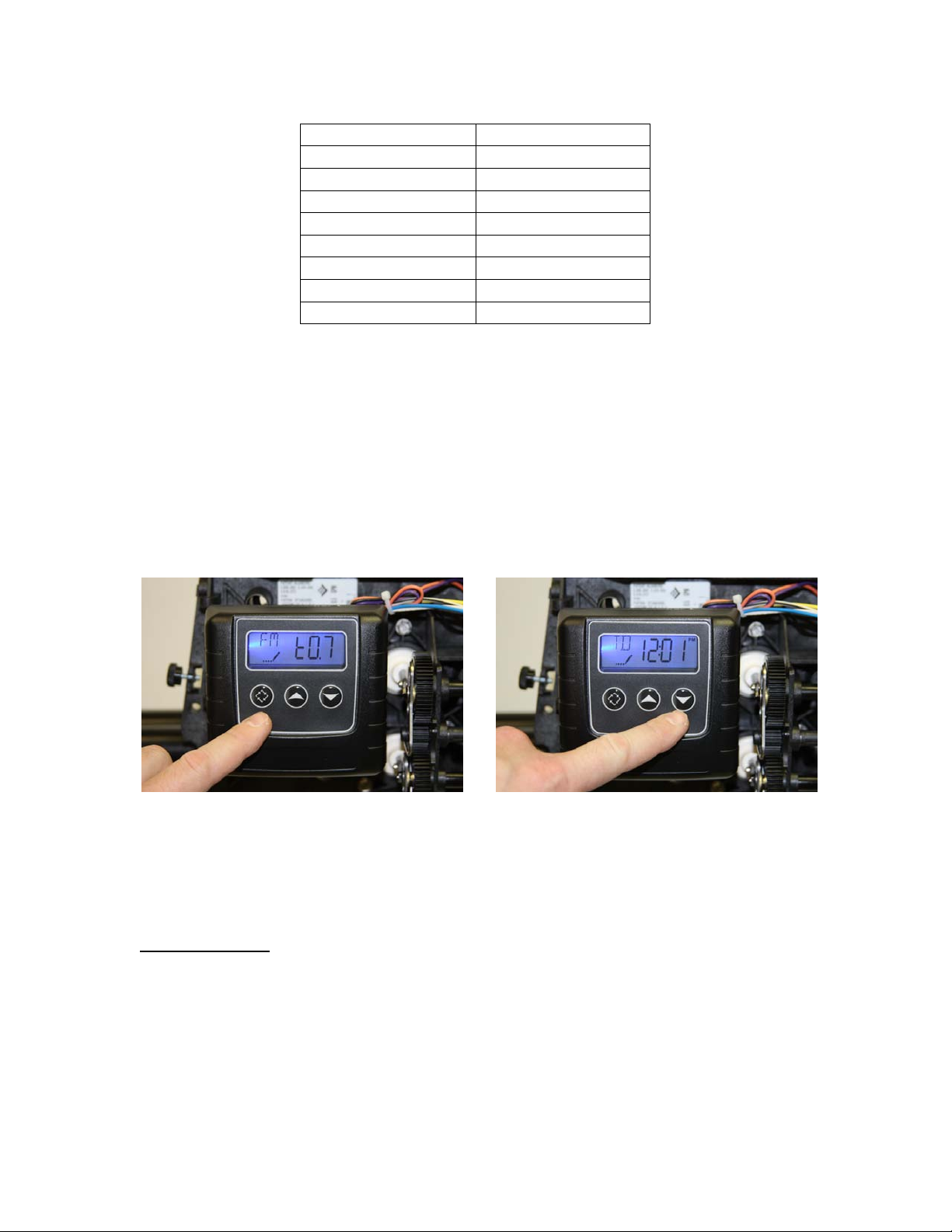
•The display may now show “FM / t0.7” as shown in figure 49 below. (This
indicates Flow Meter type 3/4" Turbine) Do not change this value, and press
the “Extra Cycle Button” once to continue – if this value is different, use the
“UP” or “DOWN” buttons to change this.
•The system will now exit the Master Programming mode, and the display should
now show the time of day, flowed by the new number of gallons remaining, as
shown in figure 50 below. Change the time of day by pressing and holding the
“UP” or “DOWN” button until the proper time setting is shown. Note that
there is a “PM” light indicator to differentiate between AM and PM times.
FIGURE 49 FIGURE 50
•Congratuations! Your new 9100SXT system is now programmed and ready for
operation. Please move on to the next section on the following page to initialize
and start-up your system.
Initial Start-Up:
•With one nearby softened faucet running in the COLD position, slowly open your
bypass valve or 3-valve bypass to about ¼ open to allow the air trapped in the
softener to escape via your running faucet. NOTE: Opening the bypass too
quickly or too open may damage your softener or plumbing.
•Allow the softener tank to slowly fill with water. After a few minutes, you will
see a trickle of water coming from the cold water faucet. Allow the water to run
System Size
Salt Time Setting
24,000 Grains
7
32,000 Grains
10
40,000 Grains
12
48,000 Grains
15
64,000 Grains
19
80,000 Grains
23
96,000 Grains
29
120,000 Grains
39

slowly in this manner for an additional 5 minutes. Next, with the cold water faucet
still running, gradually move your bypass valve to the fully open position.
NOTE: You may see some initial discoloration from the softened water – this
is normal and should dissipate within the first 40-50 gallons of water used.
•Turn off the nearby cold water faucet when the water runs clear.
•Add approximately five gallons of water to your brine tank, and add 120-160
pounds of pellet, solar, or block salt or potassium chloride to your brine tank.
Enjoy Your Softener!
Congratulations, you have successfully installed your new water softener with Fleck
9100SXT Meter Valve!
Please maintain your system by keeping the softener plugged-in and always keep your
brine tank filled with salt to at least above the water level.
We appreciate your business, and hope that you enjoy years of trouble-free softened
water!
- QualityWaterForLess.com
Other Fleck Water Dispenser manuals

Fleck
Fleck 7000 User manual

Fleck
Fleck 7000 User manual

Fleck
Fleck 7000SXT User manual

Fleck
Fleck 5600SXT Owner's manual

Fleck
Fleck 5600 Econominder User manual

Fleck
Fleck 9100TS Upflow User manual

Fleck
Fleck 5600SXT User manual

Fleck
Fleck 7000 Operating instructions

Fleck
Fleck 6700 Downflow User manual

Fleck
Fleck 5800 SXT User manual


Popular Water Dispenser manuals by other brands


Watts
Watts OneFlow OF744-10 Installation, operation and maintenance manual

Pro Pond
Pro Pond UV110 Advantage Instructions for installation and use

BRIO
BRIO CLBL520SC instruction manual

Kenmore
Kenmore GENIUS II 625.34867 owner's manual

Aquaport
Aquaport AQP-WCS Installation & operating instructions

Kenmore
Kenmore 625.343920 owner's manual