Excalibur EWS S1590 User manual

1
SOFTENER INSTALLATION AND USER GUIDE
BARRIE • ONTARIO • CANADA TF: 705.733.8900 WWW.EXCALIBURWATER.COM
TABLE OF CONTENTS
1) Installation ............................................................................................................................................ 3
1.1) Pre-installation instructions.......................................................................................................... 3
1.2) General Installation and Service Warnings................................................................................... 3
1.3) Site Requirements......................................................................................................................... 3
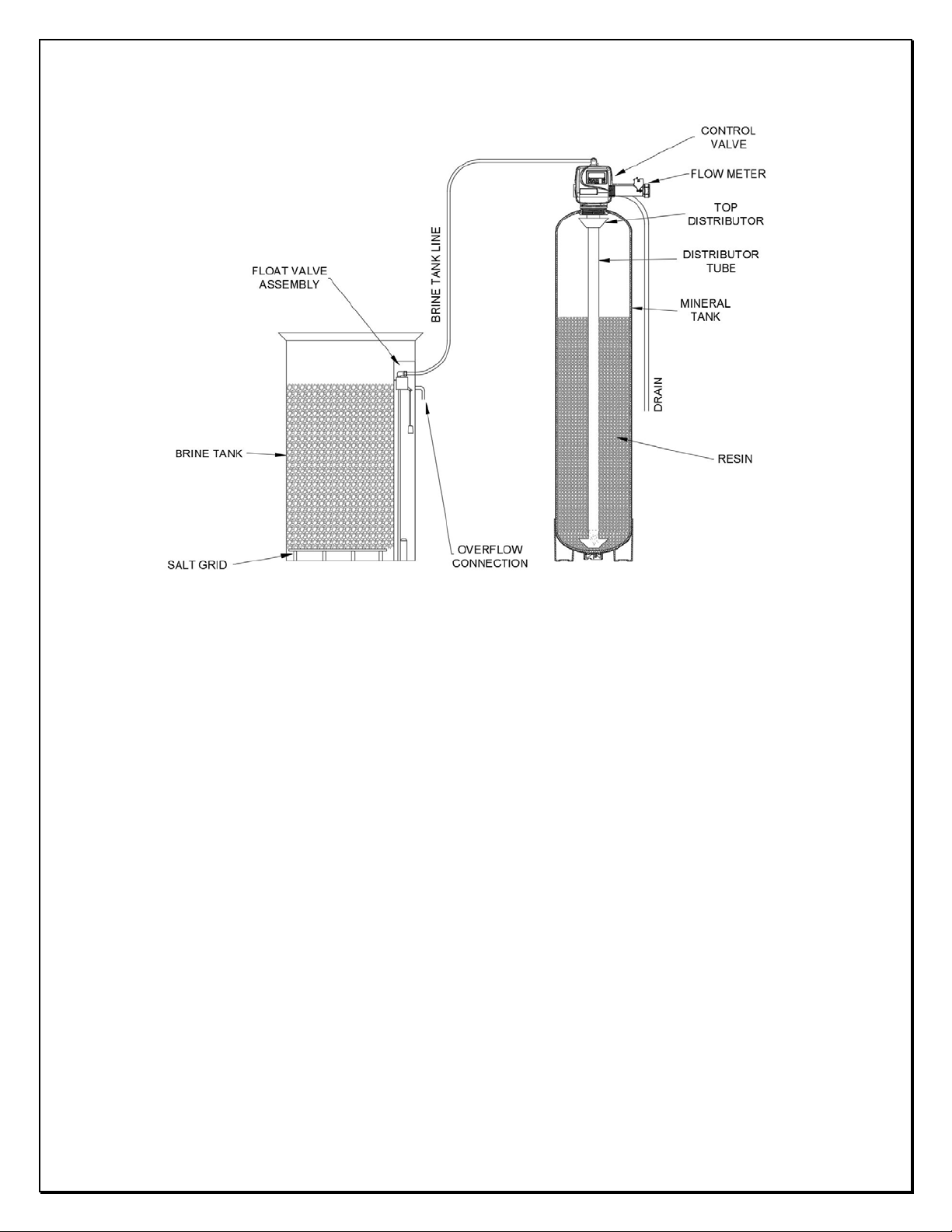
1.4) Installation Drawing ...................................................................................................................... 4
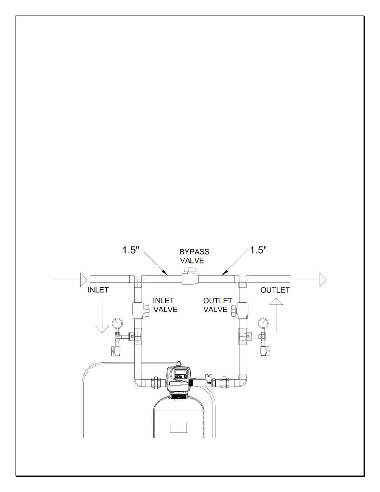
1.5) Piping and Instrumentation Drawing............................................................................................ 5
1.6) System Drawing ............................................................................................................................ 6
1.7) Plumbing ....................................................................................................................................... 6
1.8) Brine Line Connection ................................................................................................................... 6
1.9) Overflow Line Connection............................................................................................................. 7
1.10) Drain Line .................................................................................................................................. 7
1.11) 3-Way Bypass Valve .................................................................................................................. 7
1.12) Loading Instructions.................................................................................................................. 9
1.13) Start Up Instructions ............................................................................................................... 10
2) Programming ...................................................................................................................................... 11
2.1) Regeneration and Error Screens .................................................................................................11
2.2) Button Operation........................................................................................................................11
2.3) User Displays............................................................................................................................... 12
2.4) Setting Time of Day ..................................................................................................................... 13
2.5) Configuration Settings ................................................................................................................13
2.6) Installer Display Settings .............................................................................................................14
2.7) OEM Softener System Setup....................................................................................................... 15
2.8) Diagnostics ..................................................................................................................................17
3) Model Variable Programming and Components ................................................................................ 19
3.1) Programming ..............................................................................................................................19
3.2) Flow Controls and Injectors ........................................................................................................19
3.3) Specifications ..............................................................................................................................20
4) Control Valve....................................................................................................................................... 21
4.1) Control Valve Specifications........................................................................................................... 21
4.2) Control Valve Drawing ................................................................................................................23
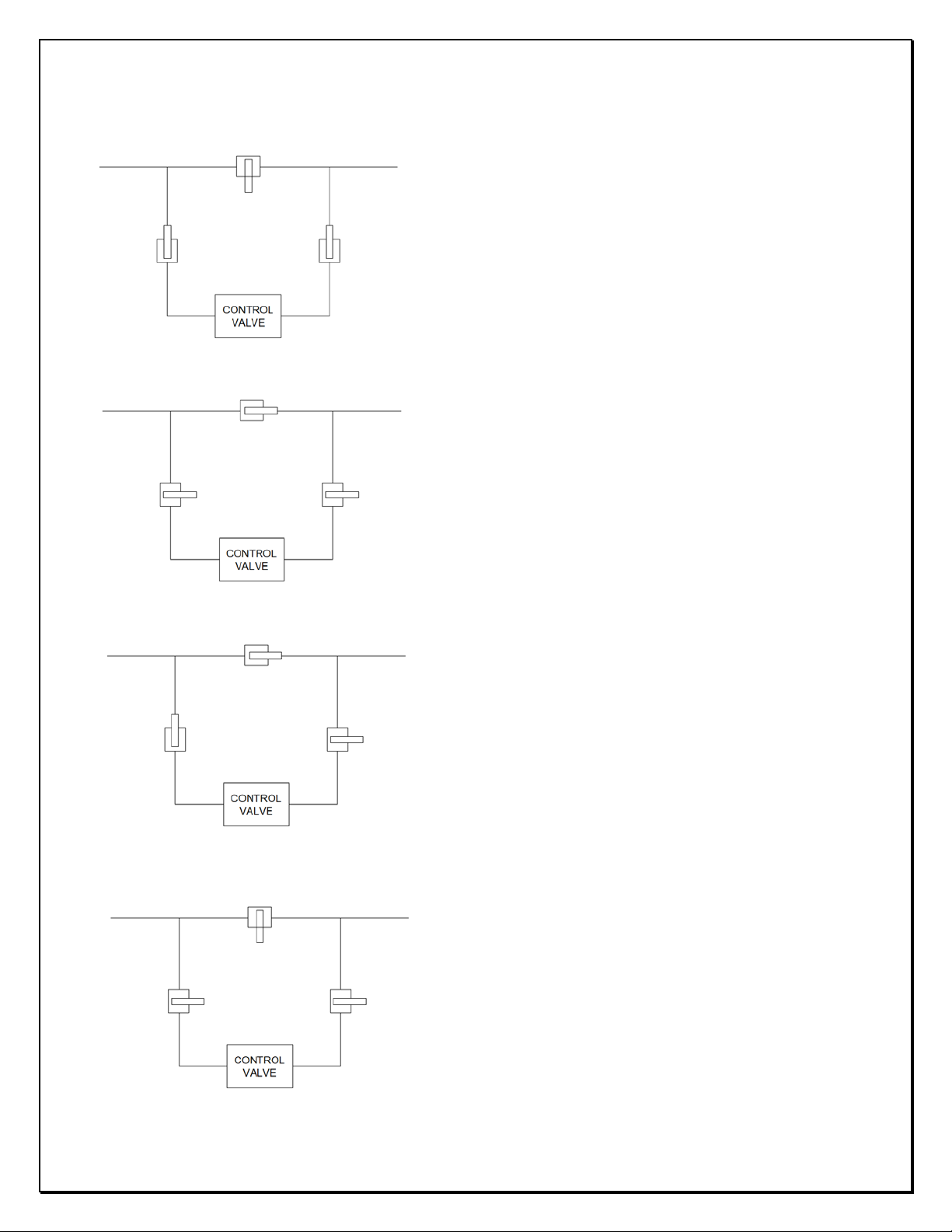
4.3) Flow Diagrams............................................................................................................................. 24
4.4) Components of Control Valve..................................................................................................... 27

2
SOFTENER INSTALLATION AND USER GUIDE
BARRIE • ONTARIO • CANADA TF: 705.733.8900 WWW.EXCALIBURWATER.COM
5) Brine Tank Assembly........................................................................................................................... 32
6) Quick Reference Guide ....................................................................................................................... 33
7) Service Instructions............................................................................................................................. 35
7.1) Front Cover Removal ..................................................................................................................35
7.2) PC Board Removal....................................................................................................................... 36
7.3) Drive Bracket Removal................................................................................................................37
7.4) Drive Cap Removal...................................................................................................................... 38
7.5) Piston Removal ...........................................................................................................................39
7.6) Stack Assembly Removal.............................................................................................................40
7.7) Injector Cap Removal..................................................................................................................41
8) Troubleshooting.................................................................................................................................. 42
8.1) Possible Error Codes ................................................................................................................... 42
8.2) Troubleshooting Procedures.......................................................................................................43
9) 5 Year Warranty .................................................................................................................................. 47

3
SOFTENER INSTALLATION AND USER GUIDE
BARRIE • ONTARIO • CANADA TF: 705.733.8900 WWW.EXCALIBURWATER.COM
1) INSTALLATION
1.1) Pre-installation instructions
The cycle times, sequence of cycles, salt dose refill time and exchange capacity are preset to default by
OEM. The installer must change the values according to the hardness, day override and time of
regeneration. Set time of day, read normal operating displays, read power loss and error displays.
WATER TEST
Hardness gpg
Iron ppm
pH number
*Nitrates ppm
Manganese ppm
Sulphur yes/no
Total Dissolved Solids
1.2) General Installation and Service Warnings
•The softener is designed so that it can be installed easily with minor plumbing changes on
previous plumbing.
•The piping must be clamped properly and the weight of the plumbing must not be on the
softener.
•Do not use any kind of lubricant including silicone. A silicone based lubricant can be only used on
O-Rings but not necessary.
•The nuts and caps can be fastened and unfastened by hand or the plastic service wrench. Do not
use pipe wrench to tighten the caps and nuts.
1.3) Site Requirements
•Water Pressure: - 40-110 psi
•Water Temperature: - 40-110°F (4.4-43°C)
•Electrical- 115/120 V, 60Hz Uninterrupted Outlet
•Current required is 0.5 Amperes
•The plug-in transformer is for dry locations only
•The tank should be on a firm level surface

6
SOFTENER INSTALLATION AND USER GUIDE
BARRIE • ONTARIO • CANADA TF: 705.733.8900 WWW.EXCALIBURWATER.COM
1.6) System Drawing
1.7) Plumbing
•The 3-way bypass valves must be installed.
•The softener must be close to drain as much as possible.
•The primer, solder or solder flux must not get on the O-rings.
•After soldering the lines must be cooled before installing the O-Rings, nuts and caps.
•If the electrical system is grounded to the plumbing than copper strap must be connected
between inlet and outlet as shown in figure above.
•The plumbing must be done by following the local plumbing codes.
•The unit including the drain must be located in a room temperature above 40° F.
•Never let the vacuum occur in tank this may cause implosion and leakage. If vacuum occurrence
is expected than vacuum breaker must be installed in line.
1.8) Brine Line Connection
Install the 1/2” or 3/4” O.D. Polyethylene tube according to specification sheet from the brine tank to
the control valve.

7
SOFTENER INSTALLATION AND USER GUIDE
BARRIE • ONTARIO • CANADA TF: 705.733.8900 WWW.EXCALIBURWATER.COM
1.9) Overflow Line Connection
The overflow drain line is used where overflow of the brine tank can damage the floor finishing or
structure. The brine tank line is equipped with safety float valve which prevents the overflow so, the
overflow line is only used in case is overflow float valve fails. The overflow line will transfer fluid from
brine tank to the drain hence prevents the spillage.
1.10) Drain Line
•Leave minimum of 6” gap between flow control fitting and solder joints. The gap less than this
can damage the flow control.
•Use ¾”, 1” or 1.25” tubing or pipe for drain line according to the specifications.
•If the drain line is elevated and then emptied into the drain below the level the of control valve
the 7” loop should make at the end of drain line.
•The air gap between the drain and the end of the drain line must be twice the diameter of the
tube or pipe
•The strap must be tied at the end to secure the line.
1.11) 3-Way Bypass Valve
The shut off valves must be installed at inlet and outlet of control valve. The bypass pipe including the
ball valve must also be installed to bypass the hard water to supply.

8
SOFTENER INSTALLATION AND USER GUIDE
BARRIE • ONTARIO • CANADA TF: 705.733.8900 WWW.EXCALIBURWATER.COM
Normal Position: - Fully close the bypass valve and fully open
both valves at inlet and outlet of the control valve. The supply
water (untreated) enters in and treated water exits.
Bypass Position: - The inlet and outlet valves at the control
valve must be fully closed but the bypass valve must be fully
open. The supply water enters and bypass the control valve
and exits untreated as supply water.
Diagnostic Position: - The outlet valve must be fully closed but
bypass valve and inlet valve must be fully open. The untreated
water will be supplied but in this position technician will be
able to draw a brine and perform other tests.
Shut Off Position: - All three valves must be at fully closed
position. The water supply is shut down means there will be
no flow at the outlet.
NORMAL POSITION
BYPASS POSITION
DIAGNOSTIC POSITION
SHUT OFF POSITION
Open
Open
Open
Open
Close
Close
Close
Close
Close
Close
Open
Open

9
SOFTENER INSTALLATION AND USER GUIDE
BARRIE • ONTARIO • CANADA TF: 705.733.8900 WWW.EXCALIBURWATER.COM
1.12) Loading Instructions
Step 1: Check the product upon arrival and remove from box packaging checking for any shipping
damage or shortages that must be reported to Excalibur Water Systems immediately for confirmation.
Step 2: Insert distributor(s) inside of media mineral tank(s) so it is positioned properly in the bottom
centre groove. If not already sized properly cut the top of the distributor pipe ½ - ¾” above top of tank
opening and clean off and excess PVC materials with grit cloth.
Step 3: Plug the top inlet opening of the distributor (Hub & Lateral) or bottom stack with a clean cloth,
rag, or tape to prevent any gravel or resin from entering into the distributor tube.
Step 4: Load the gravel under bedding onto the mineral tank using a funnel or some sort of loading
devise. If multiple layers of gravel with different sizes being utilized always load the largest gravel size in
diameter to the smallest last.
Step 5: Load the water softening cation exchange resin also by the use of a funnel or some sort of
loading device until all resin is inside of mineral tank. If loading a duplex system that has two tanks
divide the resin and gravel up equally when loading.
Step 6: Remove top opening cover of the distributor carefully not to move or disturb the distributor
tube not allowing any debris or materials to get inside of the now loaded softener(s).
Step 7: Thread on control valves onto top opening tanks be sure to check and verify that the O-ring on
the bottom base of the control valve is present and properly lubricated with silicone. Tighten control
valve(s) clockwise until you have reached the end of the thread and have secured a water tight seal. (If
control valves that utilize quick connect collars thread the collars the same into the tanks then attach
control valves).
Step 8: Precede now with the unit(s) in their proper installation locations to run piping and materials for
all inlet, outlet, and drain connections properly with isolation valves and test ports for future water
tests. Also unions should be included in installation materials for easy future servicing of the control
valves when necessary on all inlet, outlet, and drain lines.

10
SOFTENER INSTALLATION AND USER GUIDE
BARRIE • ONTARIO • CANADA TF: 705.733.8900 WWW.EXCALIBURWATER.COM
1.13) Start Up Instructions
•Keep the 3-way bypass valves in bypass position by keeping inlet and outlet valves fully closed
and bypass valve fully open. Now the untreated water is being supplied to house. Open the
faucet downstream of softener and keep it open until water comes clear out of it. The initial
water can be dirty because of installation debris. Now inspect the leaks in plumbing.
•Manually add water to brine tank so that level reaches air check valve. Press and hold the
“REGEN” button down for 5 seconds to start manual regeneration. The drive motor will start the
backwash cycle and countdown time begins. Turn the inlet valve handles halfway into the
direction of service position. Once the steady water flows out of drain then fully open the inlet
and outlet valves and fully close the bypass valve.
•When the water become clear in drain line then press the regen button to advance the
regeneration in brine cycle. Fully open the faucet and check if water is being drawn from brine
tank. Allow this cycle to run for 3 minutes.
•Press REGEN button to advance the regeneration to rinse cycle. The water will come through the
drain. Allow this process until water coming through the drain becomes clear.
•Add salt to the tank and allow ample time to dissolve it in water to become brine solution.

11
SOFTENER INSTALLATION AND USER GUIDE
BARRIE • ONTARIO • CANADA TF: 705.733.8900 WWW.EXCALIBURWATER.COM
2) PROGRAMMING
2.1) Regeneration and Error Screens
2.2) Button Operation
Regen Screen
Displays the time remaining in the current cycle. Pressing REGEN advances to the next
cycle.
Error Screen
Alternated flashing Error and error code every 3 seconds.
Clear by disconnecting the power supply at the PC board and
reconnecting, or press NEXT and REGEN simultaneously for 3
seconds.
Scrolls to the next display.
•Pressing once and releasing will schedule a regeneration at the preset delayed regeneration time.
•Pressing again and releasing will cancel the regeneration.
•Pressing and holding for 3 seconds will initiate an immediate regeneration
•Pressing while in regeneration will advance to the next cycle.
•Pressing in the program levels will go backwards to the previous screen
Change Variable being displayed.
Key sequence to lock and unlock program settings
Holding for 3 seconds initiates a control reset. The software version is displayed and the
piston returns to the home/service position, resynchronizing the valve.

12
SOFTENER INSTALLATION AND USER GUIDE
BARRIE • ONTARIO • CANADA TF: 705.733.8900 WWW.EXCALIBURWATER.COM
2.3) User Displays
When the system is operating, one of five displays may be shown.
Pressing NEXT will alternate between the displays shown below.
User 1
Typical user display. Shows volume remaining to regeneration. This
screen will not be viewed if the control is set for time-clock operation.
User 2
Displays number of days to next regeneration.
User 3
Flow Rate.
Displays present flow rate.
User 4
Displays total volume in gallons since last reset. If a meter is not used
this display will be shown but 0 will be displayed.
PRESS ▼FOR 3 SECONDS TO RESET TO 0.
User 5
Shows current time.

13
SOFTENER INSTALLATION AND USER GUIDE
BARRIE • ONTARIO • CANADA TF: 705.733.8900 WWW.EXCALIBURWATER.COM
2.4) Setting Time of Day
2.5) Configuration Settings
•Push NEXT button until time of day screen is displayed.
•Press and hold ▼until SET TIME is displayed and the hour flashes
once.
•Press ▲or ▼until the correct hour is displayed. Then press NEXT.
•The minutes will flash. Press ▲or ▼until the correct minute is
displayed. Press NEXT to return to the User Displays.
If a power outage lasts less than 8 hours and the time of day flashes on
and off, the battery should be replaced and the time should be reset.
Step 1CS – Press NEXT and ▼simultaneously for 5 seconds and
release. Press NEXT and ▼ simultaneously for 5 seconds and release. If
the screen in Step 2CS does not appear, the lock on the valve is
activated. To unlock, press ▼, NEXT, ▲and REGEN in sequence, then
press NEXT and ▼simultaneously for 5 seconds and release. Press
NEXT and ▼simultaneously for 5 seconds and release.
Step 2CS – Use ▲or ▼to select 1.5 for 1.5” valve. Press NEXT to go to
Step 3CS. Press REGEN to exit Configuration Settings.
Step 4CS – Select dP oFF – outside regeneration signal feature not used,
by using ▲or ▼buttons.
Press NEXT to go to Step 5CS. Press REGEN to return to previous step.
Step 3CS – Use ▲or ▼to select “1.5” meter size.
Press NEXT to go to Step 4CS. Press REGEN to return to previous step.

14
SOFTENER INSTALLATION AND USER GUIDE
BARRIE • ONTARIO • CANADA TF: 705.733.8900 WWW.EXCALIBURWATER.COM
2.6) Installer Display Settings
Step 1I - To enter Installer Display press NEXT and ▲simultaneously
for about 5 seconds and release.
Step 2I – Hardness: Set the amount of influent hardness using ▲or
▼.
Press NEXT to go to step 3I. Press REGEN to exit Installer Display
Settings.
Step 3I – Day Override: Set “14” maximum number of days between
regenerations using ▲or ▼:
Press NEXT to go to step 4I. Press REGEN to return to previous step.
Step 4I – Next Regeneration Time (hour): Set the hour of day for
regeneration using ▲or ▼. The default time is 2:00.
Press NEXT to go to step 5I. Press REGEN to return to previous step.
Step 5I – Next Regeneration Time (minutes): Set the minutes of day
for regeneration using ▲or ▼.
Press NEXT to exit Installer Display Settings. Press REGEN to return
to previous step.
Step 6CS – Fill Units, LBS should be selected. MIN (minutes) should be
selected only for model# EWS S15450. Press NEXT to exit OEM
Configuration Setup. Press REGEN to return to previous step.
Step 5CS – Select feature “OFF” using
▲or ▼buttons for simplex softener.

15
SOFTENER INSTALLATION AND USER GUIDE
BARRIE • ONTARIO • CANADA TF: 705.733.8900 WWW.EXCALIBURWATER.COM
2.7) OEM Softener System Setup
Step 1S - Press NEXT and ▼simultaneously for 5 seconds and
release. If screen in Step 2S does not appear, the lock on valve
programming has been activated.
Step 2S – Choose SOFTENING using ▲or ▼. Press NEXT to go to
Step 3S. Press REGEN to exit OEM Softener System Setup.
Step 3S – Choose “dn” Downflow Brining Direction using ▲or ▼.
Press NEXT to go to Step 4S. Press REGEN to return to previous step.
Step 4S – Set “POST” Refill location using ▲or ▼buttons, so that
valve must refill the brine tank after the final rinse; or
Press NEXT to go to Step 5S. Press REGEN to return to previous step.
Step 5S – Select the time for first backwash cycle using ▲or ▼
buttons. Press NEXT to go to Step 6S. Press REGEN to return to
previous step.
Step 6S – Select the time for brine cycle using ▲or ▼.
NOTE: The display will flash between cycle number and time, and
brine direction (dn).
Press NEXT to go to Step 7S. Press REGEN to return to previous step.
Step 7S – Select the time for second backwash cycle using ▲or ▼
buttons.
Press NEXT to go to Step 8S. Press REGEN to return to previous step.

16
SOFTENER INSTALLATION AND USER GUIDE
BARRIE • ONTARIO • CANADA TF: 705.733.8900 WWW.EXCALIBURWATER.COM
Step 8S – Select the time for Rinse cycle using ▲or ▼.
Press NEXT to go to Step 9S. Press REGEN to return to previous step.
Step 9S – Select the pounds for the fifth cycle using ▲or ▼.
According to the specifications of the softener model.
Press NEXT to go to Step 10S. Press REGEN to return to previous
step.
Step 10S – Set System Capacity using ▲or ▼. The System Capacity
setting should be based on the volume of resin and LBS of salt fill set
in Step 9S. Press NEXT to go to Step 11S. Press REGEN to return to
previous step.
For reference see page#24
Step 11S – Set “AUTO” Volume Capacity using ▲or ▼. The capacity
will be automatically calculated and reserve capacity will be
automatically estimated.
Press NEXT to go to Step 12S. Press REGEN to return to previous
step.
Step 12S – Set Regeneration Time “Normal + on0” Options using ▲
or ▼buttons the regeneration will occur at one of the following:
— the preset time when the volume capacity falls below the reserve
or the specified number of days between regenerations is reached
whichever comes first; or
— immediately after 10 minutes of no water usage when the
volume capacity reaches 0 (zero).
Press NEXT to go to Step 13S. Press REGEN to return to previous
step.
Step 13S – Set Relay Operation “OFF” using ▲or ▼.
Steps 14S and 15S will not be shown.
Press NEXT to go to Step 14S. Press REGEN to return to previous
step.
oFF
On 0
Exit OEM Softener System

17
SOFTENER INSTALLATION AND USER GUIDE
BARRIE • ONTARIO • CANADA TF: 705.733.8900 WWW.EXCALIBURWATER.COM
2.8) Diagnostics
Step 1D - Press ▲and ▼simultaneously for 5 seconds and release. If
screen in Step 2D does not appear the lock on the valve is activated. To
unlock press ▼, NEXT, ▲, REGEN in sequence, then press ▲and
▼simultaneously for 5 seconds and release.
Step 2D – Software Version. Press NEXT to go to Step 3D. Press REGEN to
exit Diagnostics.
Step 3D – Volume, total used since start-up: This display shows the total
gallons treated since startup. This display will equal zero if a water meter is
not installed. Press the NEXT button to go to Step 4D. Press REGEN to
return to previous step.
Step 4D – Days, total since start-up: This display shows the total days since
startup. Press the NEXT button to go to Step 5D. Press REGEN to return to
previous step.
Step 5D – Regenerations, total number since start-up: This display shows
the total number of regenerations that have occurred since startup. Press
the NEXT button to go to Step 6D. Press REGEN to return to previous step.
Step 6D – Error Log: This display shows a history of the last 10 errors
generated by the control during operation. Press ▲or ▼to view each
recorded error.
Press NEXT to go to Step 7D. Press REGEN to return to previous step.
Step 7D – Days, since last regeneration: This display shows the days since
the last regeneration occurred.
Press NEXT to go to Step 8D. Press REGEN to return to previous step.

18
SOFTENER INSTALLATION AND USER GUIDE
BARRIE • ONTARIO • CANADA TF: 705.733.8900 WWW.EXCALIBURWATER.COM
Step 9D – Volume, reserve capacity used for last 7 days. This display shows day 0 (for today) and flashes
the reserve capacity. Pressing ▲will show day 1 (which would be yesterday) and flashes the reserve
capacity used. Pressing ▲again will show day 2 (the day before yesterday) and the reserve capacity.
Keep pressing ▲to show the capacity for days 3, 4, 5 and 6. ▼can be pressed to move backwards in
the day series.
Press NEXT at any time to go to Step 10D. Press REGEN to return to previous step.
Step 10D – Volume, 63-day usage history: This display shows day 0 (for today) and flashes the volume
of water treated today. Pressing ▲will show day 1 (which would be yesterday) and flashes the volume
of water treated on that day. Continue to press ▲to show the maximum volume of water treated for
the last 63 days. If a regeneration occurred on the day the word “REGEN” will also be displayed. This
display will show dashes if a water meter is not installed.
Press NEXT to exit Diagnostics. Press REGEN to return to previous step.
Step 8D – Volume, since last regeneration: This display shows the volume of
water that has been treated since the last regeneration. This display will
equal zero when a water meter is not installed. Press NEXT to go to Step 9D.
Press REGEN to return to previous step.

19
SOFTENER INSTALLATION AND USER GUIDE
BARRIE • ONTARIO • CANADA TF: 705.733.8900 WWW.EXCALIBURWATER.COM
3) MODEL VARIABLE PROGRAMMING AND COMPONENTS
3.1) Programming
OEM Softener System Setup
Model #
Mineral
Tank
Brine
Tank
5S
6S
7S
8S
9S
10S
Step
Backwash
(Mins)
Brine
(Mins)
2nd Backwash
(Mins)
Rinse
(Mins)
Salt (LBS)
System
Capacity
(Kgr)
EWS S1590
14x65
24x41
10 75 8 6
45 (30)
90 (81)
EWS S15120
16x65
24x41
60 (40)
120 (108)
EWS S15150
18x65
24x50
75 (50)
150 (135)
EWS S15180
18x65
24x50
90 (60)
180 (162)
EWS S15210
21x62
24x50
105 (70)
210 (189)
EWS S15240
24x72
30x50
120 (80)
240 (216)
EWS S15300
24x72
30x50
150 (100)
300 (270)
EWS S15450
30x72
30x50
15 (10) mins
450 (405)
Step 6CS: - MIN only for model# EWS S15450
3.2) Flow Controls and Injectors
Model #
Mineral
Tank
Brine
Tank
Injector
Drain Flow Control
Color
Order #
Flow GPM
Drain Line Size
Order #
EWS S1590
14x65
24x41
White
V3010-15D
5.3
3/4”
V3162-053
EWS S15120
16x65
24x41
Blue
V3010-15E
6.5
V3162-065
EWS S15150
18x65
24x50
Yellow
V3010-15F
9.0
1”
V3190-090
EWS S15180
18x65
24x50
Yellow
V3010-15F
9.0
V3190-090
EWS S15210
21x62
24x50
Green
V3010-15G
11.0
V3190-110
EWS S15240
24x72
30x50
Orange
V3010-15H
15.0
1.25”
V3190-150
EWS S15300
24x72
30x50
Orange
V3010-15H
15.0
V3190-150
EWS S15450
30x72
30x50
Machined PVC
V3010-15I
25.0
V3190-250
Configuration Settings
Step #
2CS
3CS
4CS
5CS
6CS
Option
1.5
1.5
oFF
oFF
LBS
OEM Softener System Setup
Step #
2S
3S
4S
11S
12S
13S
Option
Softening
Down
Post
Auto
NORMAL + on 0
Off
Flow Rate
Identification
This manual suits for next models
7
Table of contents
Other Excalibur Water Dispenser manuals
Popular Water Dispenser manuals by other brands

Philips
Philips WP3890 user manual

Judo
Judo i-soft Installation and operating instructions

Wallgate
Wallgate PSH-23 Installation & commissioning instructions

Eclipse
Eclipse BoilerMag Installation and servicing instructions

Philips
Philips ADD4952 user manual

Water Right
Water Right IMP-844 Installation instructions & owner's manual

Prozone
Prozone PZ7 Installation guide and operation manual

BRIO
BRIO Moderna CLPOU730UVF3 user manual

Honeywell
Honeywell VE300 Installation instruction

GE
GE PNSF39Z01 Owner's Manual & Installation Instructions

Oase
Oase BioStyle 20 operating instructions

Lancaster
Lancaster 7-TFC-50 Installation, operating and service manual