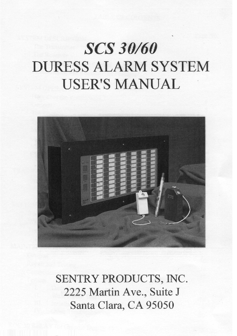
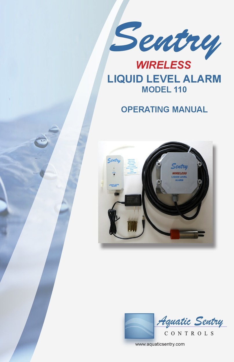
Sentry 110 User manual

Model 110 Operating Manual
Sentry Liquid Level Alarm
Page 1
Sentry
LIQUID LEVEL ALARM
MODEL 110
www.aquaticsentry.com
OPERATING MANUAL
WIRELESS

Page 2 Model 110 Operating Manual
Sentry Liquid Level Alarm
Rev 2.2 December 2020
Serial #DW110-01000 and up
TABLE OF CONTENTS
1. SAFETY PRECAUTIONS.................................................................. 3
2. APPLICATION ................................................................................... 3
2.1 HIGH Liquid Level Alarm
2.2 LOW Liquid Level Alarm
2.3 Optional Relay Output
3. INSTALLATION ................................................................................. 4
3.1 Mount Indoor Alarm Display
3.1.1 Installer Code and/or Radio Frequency
3.2 Mount the Outdoor Transmitter
3.2.1 Setting HIGH or LOW level function
3.2.2 Setting up Installer code or Radio Frequency
3.2.3 Install Batteries
3.3 Suspend the Probe
3.4 Test the alarm
3.4.1 HIGH Alarm
3.4.2 LOW Alarm
4. OPERATION and TROUBLESHOOTING........................................ 11
4.1 State Table and Troubleshooting - Indoor Alarm Display
4.2 Outdoor Enclosure Probe Assembly
4.3 Changing Installer Code or Radio Frequency
4.3.1 Program the Indoor Display
4.3.2 Program the outdoor transmitter
4.4 Wireless Transmission Timing
5. MAINTENANCE............................................................................... 14
5.1 Battery Change
6. SPECIFICATIONS ........................................................................... 15
6.1 Indoor Alarm Display
6.2 Outdoor Transmitter
6.3 IC and FCC 15 Approval
7. WARRANTY .................................................................................... 16
Printed in Canada

Model 110 Operating Manual
Sentry Liquid Level Alarm
Page 3
1. SAFETY PRECAUTIONS
The potential for electrical shock exists whenever water is present
near conductive electrical equipment. Check for sources of electricity
from other nearby devices before working on this equipment. There
is no possibility of serious shock from the energy levels used by this
alarm. The low voltage DC and transformer isolation provide safety
when handling or opening the enclosures or the probe. Best practice,
however, is to disconnect power when working on this equipment.
2. APPLICATION
The Sentry liquid level alarm continuously monitors a water level, rising
(high level) or falling (low level), that may cause an alarm condition.
Application examples are pump chambers, cisterns, holding tanks,
sumps, floor drains, irrigation channels or truck tanks. The alarm also
performs self-diagnostics, continuously testing that all components are
operating correctly. The battery powered outdoor probe communicates
with the indoor alarm display up to 90 m (300 feet) range. The indoor
alarm display will flash an LED and sound an audible alarm. Audio can
be muted with the pushbutton. When the alarm condition is corrected
the audio will reset.
• Green indicates power on and monitoring
• Red flashing and audio pulsing indicates an alarm condition
• Yellow or blue indicates an error in the wireless communication
or in the probe circuit
• Audio chirp warns of low batteries in the outdoor transmitter
See FIG 7 and section 4.1.
2.1 HIGH Liquid Level Alarm
HIGH LEVEL alarm condition occurs when the liquid level rises
to partially cover the pins on the bottom of the probe. An example
of rising water causing an alarm condition is a septic tank.

Page 4 Model 110 Operating Manual
Sentry Liquid Level Alarm
2.2 LOW Liquid Level Alarm
LOW LEVEL alarm condition occurs when the liquid level falls
below the middle of the pins of the probe. An example of falling
water level causing an alarm condition is a cistern that requires
filling.
2.3 Optional Relay Output
The relay output may be utilized to switch on remote alarms, input
to security systems, auto dialers, WiFi transmitters or control
applications. See FIG 5 and FIG 6. Set the relay operation to
Normally Open or Normally Closed with the jumper shown in
FIG 6.
3. INSTALLATION
3.1 Mount Indoor Alarm Display
Mount the Sentry indoor alarm display at a convenient viewing
location. Select an eye level location that is frequented, near a
120VAC receptacle. Power to the receptacle should be supplied
from a circuit separate from any pump that is being monitored
by this alarm. Install two supplied screws, 3” apart vertically
and projecting ¼” from the wall, to mount the display. Install
the AC adapter and plug into the alarm display. The LED will
be steady yellow with a continuous audio, indicating no wireless
communication. The supplied labels may be used to identify the
indoor alarm display’s function, ie HIGH LEVEL in the SUMP.
Radio transmission is improved by mounting away from sheet
metal or electrical wiring. Clear line of sight is the best situation.
3.1.1 Installer Code and/or Radio Frequency
If an installation requires multiple alarms, or if interference
with other radio devices occurs, change the installer
code and / or the frequency program. See section 4.3.
3.2 Mount the Outdoor Transmitter
Mount the Sentry outdoor transmitter near the water source to
be monitored. Fasten the weatherproof NEMA 6P enclosure to
a post or a riser pipe above grade using screws supplied. Radio

Model 110 Operating Manual
Sentry Liquid Level Alarm
Page 5
transmission is improved by mounting the transmitter higher off
grade. For access to disconnect probe wire see 4.2
3.2.1 Setting HIGH or LOW level function
The jumper position inside the outdoor transmitter
determines the HIGH LEVEL or LOW LEVEL function
to suit your application. See FIG 3. Using needle nosed
pliers, install the jumper, shorting the two terminals for a
HIGH LEVEL function. For a LOW LEVEL function the
jumper is installed on one terminal.
3.2.2 Setting up Installer code or Radio Frequency
If an installation requires multiple alarms, or if interference
with other radio devices occurs, change the installer
code and / or the frequency program. See section 4.3.
3.2.3 Install Batteries
Install the four AA cell batteries supplied.
3.3 Suspend the Probe
Suspend the probe at the depth the alarm is required. The
probe’s alarm point occurs when the pins are immersed 3/8” in
water
3.4 Test the alarm
3.4.1 HIGH Alarm
For a HIGH ALARM the LED will be green and on
steady with the probe out of the liquid. When the probe
is lowered into the liquid, the LED will turn flashing red
and the audible alarm will pulse. Silence the audible

Page 6 Model 110 Operating Manual
Sentry Liquid Level Alarm
alarm. Raise the probe out of the liquid to stop the red
LED flashing and to reset the audible alarm. Repeat this
sequence to prove operation. For any other conditions
see the State Table in section 4.1.
3.4.2 LOW Alarm
For a LOW ALARM the LED should be green and on
steady with the probe in the liquid. When the probe is
raised above the water, the LED will turn flashing red
and the audible alarm will pulse. Silence the audible
alarm. When the probe is lowered into the liquid the LED
will turn steady green indicating alarm is monitoring.
Repeat this sequence to prove the operation. For any
other conditions see the State Table in section 4.1.

Model 110 Operating Manual
Sentry Liquid Level Alarm
Page 7
FIG 1
Indoor Alarm Display Interior

Page 8 Model 110 Operating Manual
Sentry Liquid Level Alarm
FIG 2
Outdoor Transmitter Enclosure Cover Interior
FIG 3
Outdoor Transmitter Enclosure Interior Close-up

Model 110 Operating Manual
Sentry Liquid Level Alarm
Page 9
FIG 5
Optional Relay Output
FIG 4
Outdoor Transmitter Batteries Installed

Page 10 Model 110 Operating Manual
Sentry Liquid Level Alarm
FIG 6
Indoor Alarm Display
Setting relay to Normally Open or Normally Closed

Model 110 Operating Manual
Sentry Liquid Level Alarm
Page 11
FIG 7
Indoor Alarm Display Rear Cover Operating Instructions

Page 12 Model 110 Operating Manual
Sentry Liquid Level Alarm
4. OPERATION and TROUBLESHOOTING
4.1 State Table and Troubleshooting - Indoor Alarm Display
LED AUDIO HIGH LEVEL
(i.e. Septic tank)
LOW LEVEL
(i.e. Cistern) CORRECTIVE ACTION
OFF OFF No Power
Check breaker
Check Transformer
Check plug into display
GREEN
STEADY OFF PROBE DRY PROBE
WET OK
RED
FLASHING PULSING ALARM -
PROBE WET
ALARM
- PROBE
DRY
OK
RED
FLASHING MUTED ALARM -
PROBE WET
ALARM
- PROBE
DRY
OK
RED
STEADY OFF DISPLAY GOING INTO
PROGRAMMING MODE See 4.3.1
YELLOW
FLASHING PULSING MANUAL TEST OK
YELLOW
STEADY CONTINUOUS NO WIRELESS SIGNAL
Replace batteries (See 5.1)
Check for radio interference
Change radio frequency Transmitter
out of range
GREEN /
YELLOW
FLASHING
OR BLUE
CONTINUOUS PROBE ERROR Replace probe
RED
STEADY CONTINUOUS PROBE OR ELECTRONICS
SHORTING
Check polarity of probe conductors
Check the probe wire for damage
Check outdoor transmitter interior for
moisture
Replace probe
RED /
YELLOW
FLASHING
CONTINUOUS LOW VOLTAGE OR
PROBE DISCONNECTED
Check battery polarity
Connect probe wires (See FIG 4)
Check probe wire for damage; make a
waterproof repair
As it was CHIRP LOW BATTERY Replace batteries (See 5.1)

Model 110 Operating Manual
Sentry Liquid Level Alarm
Page 13
4.2 Probe Assembly
To access the probe wire terminal block, tilt and lift out the
electronic board. See FIG 4. Tilt the board by pressing down on
the lower right corner, at the serial number.
4.3 Changing Installer Code or Radio Frequency
If an installation requires multiple alarms change the programmed
installer code of both the indoor display and the outdoor
transmitter. If there is interference with the wireless signal
change the frequency. There are 16 installer code combinations
and 12 frequencies for a total of 192 combinations.
The installer code factory preset is all jumpers installed non-
shorting. Set an installer code unique to your installation by
installing one or more jumpers shorting the pins and then go into
programming mode.
The frequency factory preset is frequency 3.
Select channel 1 or 2 by installing the jumper off one pin for
Factory
preset
Channel # 1 2 12 1 2 1 2 1 2 1 2
Flashes 123 4 5 6
Frequency 1 2 34 5 6 7 8 9 10 11 12
channel 1 or shorting the pins for channel 2. Flash the LED once
or up to 6 times to select a frequency.

Page 14 Model 110 Operating Manual
Sentry Liquid Level Alarm
4.3.1 Program the Indoor Display
• Disconnect power from the indoor alarm display.
• Open the back cover of the display and move the
jumpers for the code and the channel. See FIG 1.
Replace the cover.
• Hold the Silence button down while connecting
power. The LED will turn on bright red indicating that
programming mode is entered. Release the button
and the LED will go out.
• Within 5 seconds, press the button down until the
LED turns on bright red. Perform this 1 to 6 times to
select the number of Flashes.
• Wait for 5 seconds, and the LED will flash back
what has been programmed.After another 5 second
delay it will flash once or twice confirming the
channel setting. The display will then go into normal
operation.
4.3.2 Program the outdoor transmitter
• Disconnect the power from the outdoor transmitter
by removing a battery. Discharge the capacitance by
using a short length of wire to short out the red and
black wires of the battery holder.
• Move the installer code and channel jumpers to your
selected position. See FIG 3.
• Hold down the push-button switch while installing the
last battery. The LED will turn on bright red indicating
that programming mode is entered. Release the
push-button and the LED will go out.
• Within 5 seconds, press the button down until the
LED turns on bright red. Perform this 1 to 6 times to
select the number of Flashes.
• Wait for 5 seconds, and the LED will flash back what
has been programmed.After another 5 second delay
it will flash once or twice confirming the channel
setting. The transmitter will then go into normal
operation.

Model 110 Operating Manual
Sentry Liquid Level Alarm
Page 15
4.4 Wireless Transmission Timing
The wireless transmissions are timed to optimize battery life.
The indoor alarm display will respond within 3 seconds to a
change in alarm state after wireless communications have been
established. The indoor alarm display receives an update from
the outdoor transmitter every 3.5 minutes. It will take 10 minutes
for the indoor alarm display to indicate that no wireless signal
has been received (yellow steady) after the battery has been
removed.
5. MAINTENANCE
5.1 Battery Change
Four AA cell long life alkaline batteries power the outdoor
transmitter. See FIG 4. Follow the diagrams on the battery holder
for correct battery installation; positive and negative battery ends
installed as shown on the battery holder. Replacement batteries
must be new, fresh and replaced as a set of four.

Page 16 Model 110 Operating Manual
Sentry Liquid Level Alarm
6. SPECIFICATIONS
6.1 Indoor Alarm Display
Power Supply 120VAC, 60 Hz input, 12VDC 5W output, UL
listed, CSA certified, indoor unit, power con-
sumption typically .05 watts, 0.9 watts maximum
during alarm condition
Enclosure flame retardant ABS
High level, Low level function selectable
LED tricolor
Audible alarm solid state transducer, 80db @ 10cm
Transceiver ISM 2.4GHz, 12 channels available, -40°C to
85°C rated, IC and FCC 15 approved
6.2 Outdoor Transmitter
Power four AA batteries, battery life 3 years under nor-
mal operation
Enclosure PVC NEMA 6P
High level, Low level function selectable
Transceiver ISM 2.4GHz, 12 channels available, -40°C to
85°C rated, IC and FCC 15 approved
Probe digital RF proximity, stainless steel, type 304 or
316, 22mm diameter x 100mm long, cable - 2
conductor, 18 Ga, SJOOW jacket, 5m (16 feet)
or 10m (32 feet)
Optional relay
output
dry contacts normally open, 2A @ 30 VAC or
VDC
6.3 IC and FCC 15 Approval
Contains Model XBEE3-PRO Radio, IC:1846A-XBS2C
Contains FCC ID: MCQ-XBEE3-PRO
The enclosed device complies with part 15 of the FCC Rules.
Operation is subject to the following two conditions: (i) this
device may not cause harmful interference and (ii) this device
must accept any interference received, including interference
that may cause undesired operation.

Model 110 Operating Manual
Sentry Liquid Level Alarm
Page 17
7. WARRANTY
Aquatic Sentry Controls Inc. warrants that this product is free from defects in
materials and workmanship under normal use and service for a period of three
years from the date of purchase by the initial owner. Aquatic Sentry shall be
responsible only for actual loss or damage suffered and then only to the extent
of Aquatic Sentry’s invoiced price. Within the warranty period we shall repair,
refurbish or replace, at our option, such products or components, which are
returned to us with shipping charges prepaid, and which are determined by
us to be defective. This warranty will not apply to any product or part thereof
which has been subject to misuse, negligence, or accident; or misapplied;
or modified; or repaired by unauthorized persons; or improperly installed.
The provisions of the above warranty are our sole obligation and exclude all
other remedies or warranties, expressed or implied, including warranties of
merchantability and fitness for a particular purpose, whether or not purposes
or specifications are described herein. We further disclaim any responsibility
whatsoever to the customer, or to any person, for injury to person, damage to,
or loss of property or value caused by any product, regardless of whether the
defect is warrantable or whether the product has been subjected to misuse,
negligence, accident; or modified or repaired by unauthorized persons; or
improperly installed.
Under no circumstances shall the company be liable for any incidental,
consequential or special damages, loss or expenses arising from the use of
this product, or in connection with the use of, or inability to use, our product
for any other purpose whatsoever.
Aquatic Sentry products or parts thereof assumed to be defective by the
purchaser within the stipulated warranty period should be returned to the
seller or local distributor for evaluation and service. If deemed necessary, the
seller or distributor shall contact Aquatic Sentry Controls Inc. for a Returned
Materials Authorization and then return the item for direct factory evaluation,
service or replacement. No material may be returned to Aquatic Sentry
Controls Inc. without proper factory authorization.

Page 18 Model 110 Operating Manual
Sentry Liquid Level Alarm
NOTES

Model 110 Operating Manual
Sentry Liquid Level Alarm
Page 19
NOTES

www.aquaticsentry.com
Other manuals for 110
1
Table of contents
Other Sentry Security System manuals