Fantini Cosmi CH193VMC User manual

CH193VMC
CENTRALISED CONTROL
FOR VMC UNITS
Code: AP 20048
AP 20050
AP 20052
AP 20054
AP 20056
AP 20058
INSTRUCTIONS FOR USE
FANTINI COSMI S.p.A.
Via dell’Osio, 6 20049 Caleppio di Settala, Milan – ITALY
Tel. +39 02 956821 | Fax +39 02 95307006 | info@fantinicosmi.it
www.fantinicosmi.it

2
CENTRALISED CONTROL FOR VMC UNITS
CH193VMC
Thank you for purchasing a FANTINI COSMI S.p.A. product.
Please read this instruction manual carefully and always keep it at hand should you need to consult it for any reason.
The documentation reflects the characteristics of the product. However, for regulatory or commercial developments,
customers should verify the availability of updates relating to this documentation on the FANTINI COSMI S.p.A.
website: pdf.fantinicosmi.it
OPERATION
CH193VMC is an LCD remote panel for the advanced control of ventilation systems through VMC. Equipped with
temperature, relative humidity and VOC sensors, it automatically controls ventilation and indoor air quality (IAQ).
Note:
The CH193VMC has been designed to work with different machines.
When switching on for the first time, as already indicated in the manual, the machine to which the device is to be
connected must be chosen.
CONTENTS OF PACKAGE
■1 VMC control panel
■2 6/32UNC American standard thread screws to secure onto 503 recessed box (approximately Ø 3.5mm)
■1 quick guide
■1 cable (cod. 1598122) to be used with the EXT IN input set to DH/IN for an external dehumidification and integration
request. (Can be used on AP 20060-AP 20062 machines).

3
CENTRALISED CONTROL FOR VMC UNITS
CH193VMC
DESCRIPTION OF DISPLAY KEYS
1 Day of the week
2 Heating/cooling coil activation state (if the VMC is set up for this)
3 Room temperature (Celsius/Fahrenheit) detected
4 Multi-function touch icons
5 VMC ventilation status
6 Operating mode
7 Bar graph to display messages and daily programming
Please note: the function of the multi-function keys varies depending on the situation and is described by the symbol
that appears on the display next to the key.
The first time any touch key is pressed, this activates the functions
of the buttons themselves and lights up the display.
1 2
6
7
4
3
5

4
CENTRALISED CONTROL FOR VMC UNITS
CH193VMC
TECHNICAL FEATURES
Rated power supply voltage 9 - 24 Vcc
Absorbed current 150 mA Max
Backlight switch-off 60s after last touch
Temperature regulation scale 5 ÷ 35 °C, increase 0.1°C
Measurement scale room T - 50 to + 50 °C, resolution 0.1°C
Relative humidity adjustment scale 30 ÷ 70 % resolution 1%
Room relative humidity display scale 0 ÷ 100 % increase 1%
Air quality view via VOC sensor
Communication interface RS485
Communication mode ModBus RTU (master)
Data formats 9600 bps
8 bits
no parity
1 bit stop
Maximum room temperature 45°C
Storage temperature -10°C ÷ +60°C
Rated pulse voltage 4000V
Software Class A
Insulation class Class II
Protection rating IP30
Degree of pollution 2
Number of operating cycles for manual actions 3000
Number of operating cycles for automatic actions 10000
Type of installation wall-mounted or on flush mounting box
Dimensions 127 x 82 x 14 mm
Weight 0.100 Kg
Compliant with ■EN 60730-1 and second parts
■Directive 2014/30/EU (EMC)
■Directive 2014/35/EU (LVD)
ErP classification ■ErP Class IV; 2%
[Reg. EU 811/2013 - 813/2013]
Product made in Italy

5
CENTRALISED CONTROL FOR VMC UNITS
CH193VMC
Contents
OPERATION ..................................................................... 2
CONTENTS OF PACKAGE................................................. 2
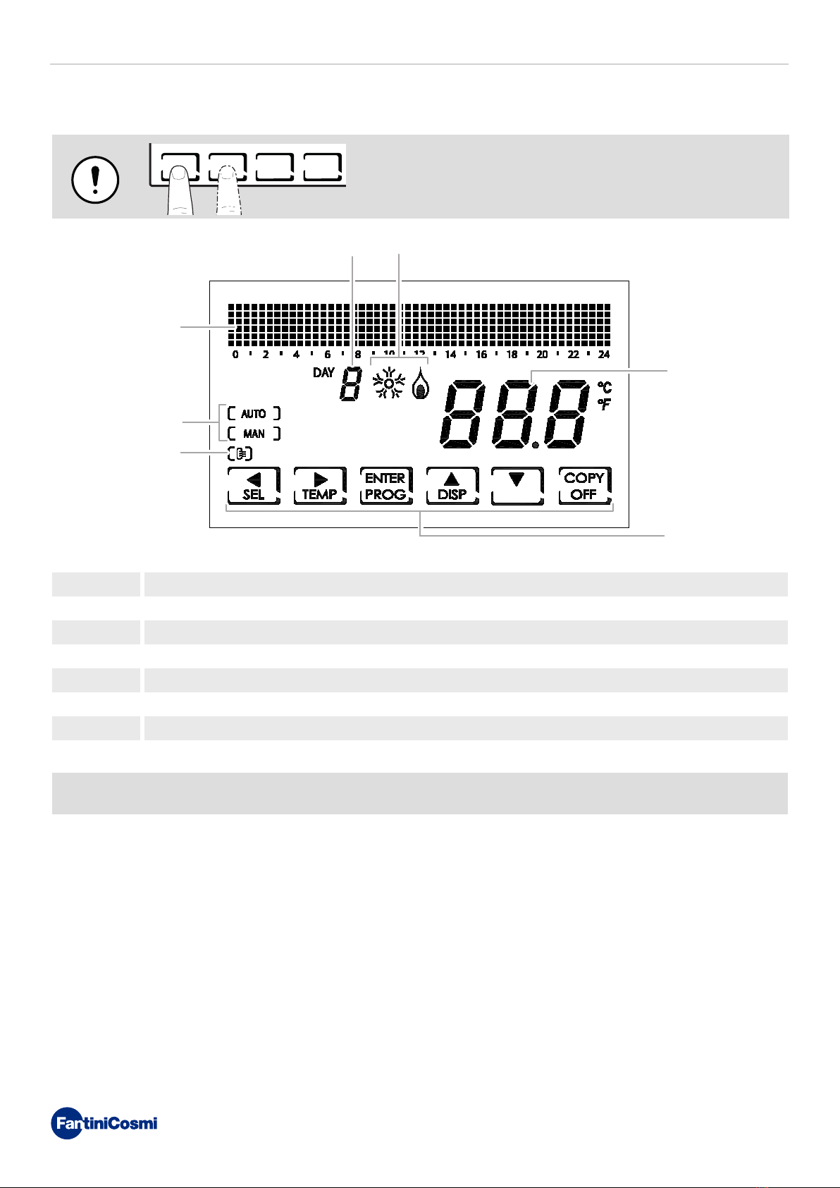
DESCRIPTION OF DISPLAY KEYS .................................... 3
TECHNICAL FEATURES ................................................... 4
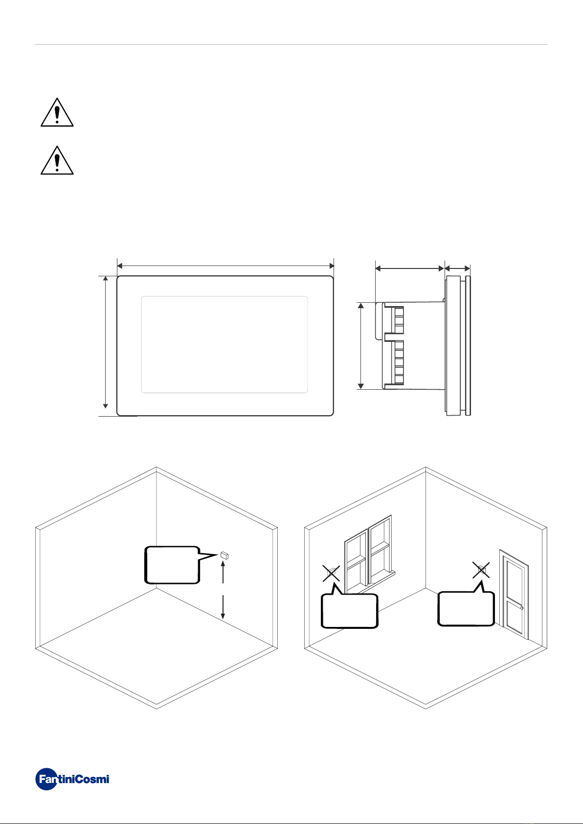
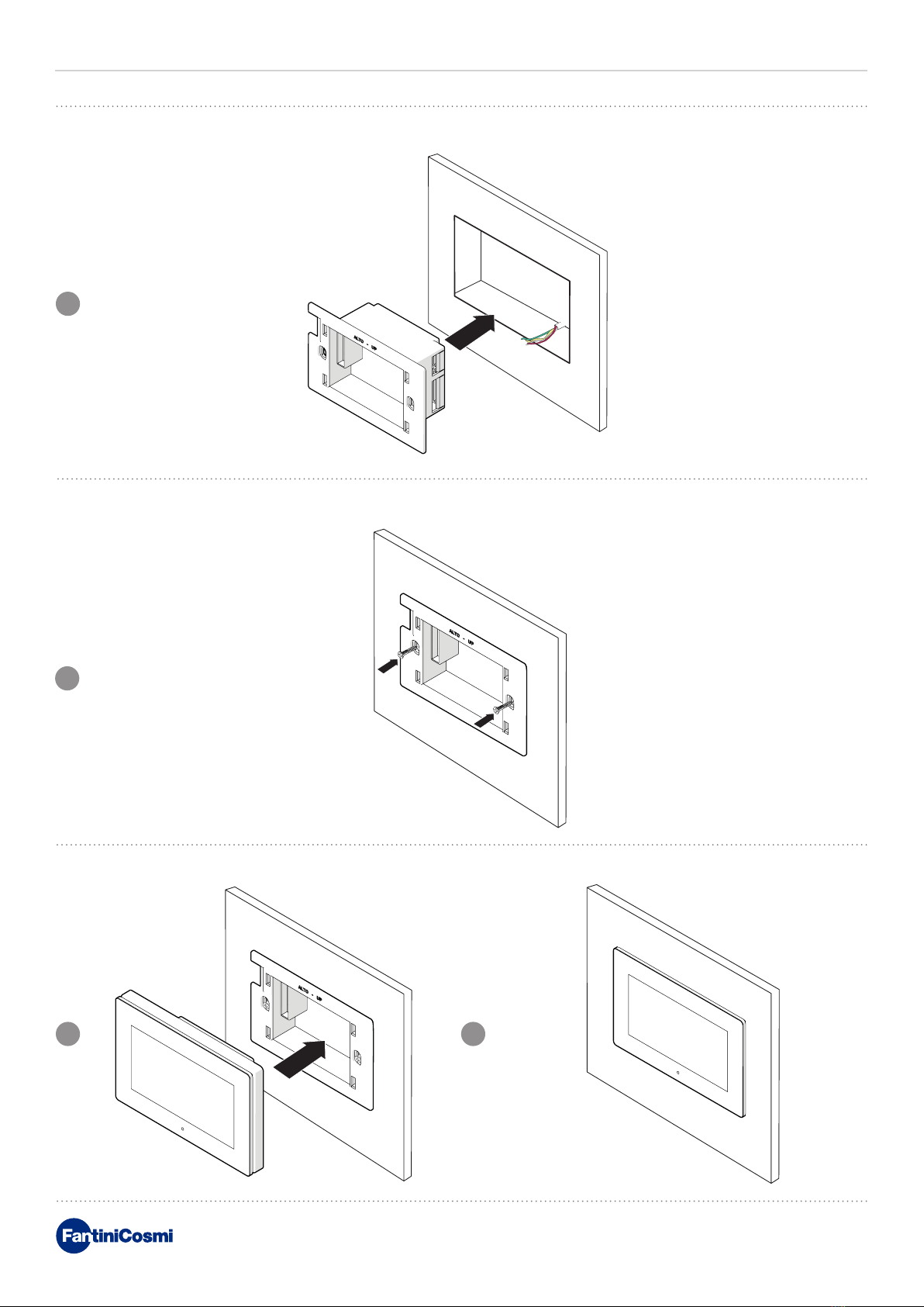
1 - INSTALLATION ........................................................... 6
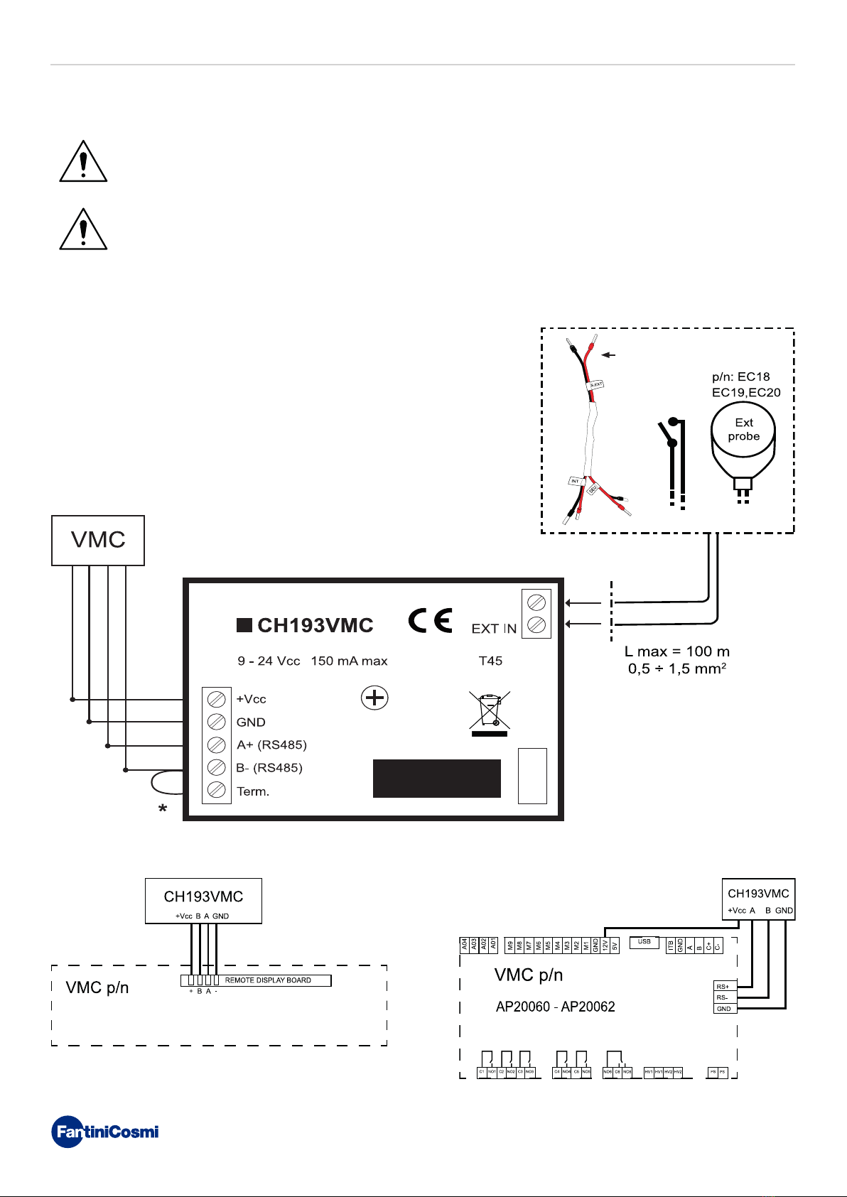
2 - ELECTRICAL CONNECTION........................................ 8
2.1 - VMC SIDE CONNECTION ......................................................9
2.2 -
CONNECTION FOR INTEGRATION AND DEHUMIDIFICATION
THROUGH THE "EXT IN" INPUT WITH EXTERNAL CABLE (cod. 1598122)
..9
2.3 - START-UP .............................................................................9
3 - USER FUNCTIONS (PROG)........................................ 10
3.1 - DATE AND TIME SETTING ..................................................10
3.2 - WINTER/SUMMER SETTING ..............................................11
3.3 - PROGRAMMING SETTING VMC PROFILE ..........................11
3.4 - SETTING MACHINE OPERATION IN INTEGRATION ...........12
3.5 - Vmc PANEL DISPLAY SETTINGS........................................14
3.6 - SETTING KEYBOARD LOCK WITH PASSWORD ..................15
4 - OPERATING PROGRAMS (SEL)................................. 16
4.1 - SELECTING THE OPERATING PROGRAM...........................17
5 - OPERATION (TEMP).................................................. 18
5.1 -
VMC (DISPLAYED ONLY WITH INTEGRATION SWITCHED OFF)... 18
5.2 -
T MAN (CAN BE DISPLAYED WITH THE INTEGRATION FUNCTION
ACTIVE AND THE TEMPERATURE SET POINT IN MANUAL).................. 18
5.3 -
T ECO / T COMF (CAN BE DISPLAYED WITH INTEGRATION FUNCTION
ACTIVE AND SETTING THE TEMPERATURE SET POINT IN AUTOMATIC MODE)
19
6 - PARAMETER DISPLAY (DISP) ................................... 20
6.1 - DATE AND TIME..................................................................20
6.2 - SEASON ..............................................................................20
6.3 - VMC PROFILE (THE PROFILE ACCORDING TO THE
PREVIOUS SETTINGS IS DISPLAYED).........................................20
6.4 - INTEGRATION (ONLY AVAILABLE WITH THE INTEGRATION
FUNCTION ACTIVE).....................................................................21
6.5 -
AIR (RETURN AIR TEMPERATURE PROBE INSIDE THE VMC).
21
6.6 -
H2 (EXHAUST AIR TEMPERATURE PROBE INSIDE THE VMC)
..21
6.7 - H4 (OUTDOOR AIR INTAKE PROBE POSITIONED INSIDE
THE VMC) ....................................................................................22
6.8 - EXT (USED INPUT DISPLAY)...............................................22
6.9 - RH (RELATIVE HUMIDITY PROBE DISPLAY) ......................22
6.10 - IAQ (AIR QUALITY PROBE DISPLAY).................................23
6.11 - DEW P (DISPLAY OF THE DEW POINT) ............................23
6.12 - HOURS OF USE.................................................................24
7 - ADVANCED FUNCTIONS (PROG) .............................. 25
7.1 - SWITCHING ON DISPLAY....................................................25
7.2 - DISPLAY LIGHTING INTENSITY ..........................................25
7.3 - DAYLIGHT SAVING / STANDARD TIME ...............................26
7.4 - VMC/ EXT HEAT...................................................................26
7.5 - VENTILATION......................................................................27
7.5.1 - V1............................................................................................27
7.5.2 - V3............................................................................................28
7.5.3 - BOOST ....................................................................................28
7.5.4 - INT..........................................................................................29
7.6 -
INTEGRATION (THIS FUNCTION IS ONLY VISIBLE WHEN
EXT HEAT IS ACTIVE) ..................................................................30
7.6.1 - MINIMUM TEMPERATURE.....................................................30
7.6.2 - MAXIMUM TEMPERATURE ....................................................31
7.6.3 - DIFFERENTIAL MANAGEMENT .............................................31
7.6.4 - ANTIFREEZE TEMPERATURE................................................32
7.7 - ROOM TEMPERATURE CORRECTION ................................32
7.8 - CELSIUS / FAHRENHEIT ....................................................33
7.9 - BY PASS (ONLY AVAILABLE WITH SUMMER FUNCTION) ....33
7.10 - SENS .................................................................................34
7.10.1 - RH.........................................................................................34
7.10.2 - VOC .......................................................................................35
7.11 - FILT ...................................................................................36
7.12 - LANGUAGE SELECTION ...................................................36
7.13 - ALARMS ............................................................................37
7.14 - CHG...................................................................................38
7.15 - EXT IN ...............................................................................38
7.16 - SOUND ALARM.................................................................39
7.17 - BEEP .................................................................................39
7.18 - LED ...................................................................................40
7.19 - INFORMATION ..................................................................40
7.20 - RESETTING DEFAULT PARAMETERS...............................41
8 - DISPOSAL................................................................. 42
9 - GENERAL WARRANTY CONDITIONS ........................ 42

mm mm
mm
127
82
1441
52 mm
mm
6
CENTRALISED CONTROL FOR VMC UNITS
CH193VMC
1 - INSTALLATION
ATTENTION!
Installation must be carried out by qualified personnel in compliance with the requirements concerning
the installation of electrical equipment.
ATTENTION!
Installation operations must be performed with the system’s power disconnected.
CH193VMC must be installed on the wall or on a flush mounting box, in 3 units, at a height of about 1.5m from the floor,
in a suitable position to detect the room temperature correctly.
1.5 m
OK
NO NO

2
1
3 4
7
CENTRALISED CONTROL FOR VMC UNITS
CH193VMC
Place the rear body in the wall box.
Make the electrical connections (refer to “2 - ELECTRICAL CONNECTION”) and secure the rear body to the wall with the
screws provided.
Hook the front of the control unit onto the rear wall body.

AP20048 - AP20050 - AP20052 - AP20054 - AP20056
AP20058 - AP20064 - AP20066
8
CENTRALISED CONTROL FOR VMC UNITS
CH193VMC
2 - ELECTRICAL CONNECTION
ATTENTION!
Electrical connections must be made by qualified personnel.
ATTENTION!
Electrical connection operations must be done with the system’s power disconnected.
CH193VMC is connected directly to the Fantini Cosmi VMC machines. The connection changes based on the VMC code.
*Note: Jump the terminals.
Use a shielded cable and ground it on the CH193VMC side.
(Code 1598122)

AP20048 - AP20050
AP20052 - AP20054
AP20056 - AP20058
AP20064 - AP 20066
*
*
Assicurarsi che il jumper sia inserito correttamente
9
CENTRALISED CONTROL FOR VMC UNITS
CH193VMC
2.1 - VMC SIDE CONNECTION
2.2 - CONNECTION FOR INTEGRATION AND DEHUMIDIFICATION
THROUGH THE "EXT IN" INPUT WITH EXTERNAL CABLE (cod. 1598122)
The cable cod. 1598122 can be used with AP 20060 and AP 20062 when there is an external demand for dehumidification
and/or heating/cooling integration.
For all other machines, a direct connection to the EXT IN input is sufficient.
It is necessary to set from “Advanced User" the EXT IN input to DH/IN.
2.3 - START-UP
At first switch-on, the CH193VMC must be coupled to a VMC. Choose the code of the installed VMC.
1
VMC SELECT
ENTER
AP20048
AP20050
AP20052
AP20054
AP20056
AP20058
AP20060
AP20062
AP20064
AP20066
PRESS
ENTER
Dehumidification
request relay
* Ensure that the jumper is correctly inserted
Integration
request relay
heating / cooling

CH193VMC
10
CENTRALISED CONTROL FOR VMC UNITS
3 - USER FUNCTIONS (PROG)
The first time any touch key is pressed has no effect, but only activates the functions of the buttons themselves and
lights up the display.
After 60 seconds of no interaction, the display goes back to the main screen.
= allows you to CONFIRM = allows you to PROGRAM
3.1 - DATE AND TIME SETTING
Note: by pressing always allows you to go back to the previous page.
Note: To change the settings use the UP and DOWN arrows and the RIGHT and LEFT arrows to go forward or backward.
2s
PRESS
PRESS
ENTER
2
ENTER PROG
PRESS
PRESS
PRESS
1
3
15:25 15-09-20
23.0
SEL TEMP PROG DISP OFF
USER PROGR
DATE AND TIME
WINTER
VMC PROFILE
TEMP: AUTO
DISP: VMC
LOCK NO
DATE AND TIME
PROG
DAY 9
ENTER
MONTH 11
ENTER
YEAR 2018
ENTER
HOURS 12:0212:
ENTER
MIN
ENTER
12:02

CH193VMC
11
CENTRALISED CONTROL FOR VMC UNITS
3.2 - WINTER/SUMMER SETTING
Note: pressing or allows you to scroll through the hours.
3.3 - PROGRAMMING SETTING VMC PROFILE
On the remote panel you can set the ventilation profiles (fan speeds) of the
VMC on 7 days and different for Summer/Winter.
2s
2
1
15:25 15-09-20
23.0
SEL TEMP PROG DISP OFF
USER PROGR
DATE AND TIME
WINTER
VMC PROFILE
TEMP: AUTO
DISP: VMC
LOCK NO
DATE AND TIME
PROG
PRESS
x1
WINTER
ENTER
WINTER
SUMMER
PRESS
ENTER
2s
2
1
15:25 15-09-20
23.0
SEL TEMP PROG DISP OFF
USER PROGR
DATE AND TIME
WINTER
VMC PROFILE
TEMP: AUTO
DISP: VMC
LOCK NO
DATE AND TIME
PROG
PRESS
x2
VMC PROFILE
PROG
3
PRESS
ENTER COPY
1
DAY
1

CH193VMC
12
CENTRALISED CONTROL FOR VMC UNITS
Pressing or allows you to select the VMC profile depending on the time.
SETTABLE SPEEDS:
■OFF
■1 = V1
■2 = V2
■3 = V3
■Pressing ENTER to go to the next day.
■Pressing COPY allows you to copy the temperature profile displayed to the following day.
3.4 - SETTING MACHINE OPERATION IN INTEGRATION
Note: it is possible to set the machine for manual operation (T MAN) and automatic operation (T ECO/TCOMF).
When TEMP is selected: AUTO is displayed, then follow the procedure described in 3 and 4.
Note: Can be set from the "Advanced Programming" menu.
If the machine is designed to integrate heating and/or cooling, it is possible
to set the temperature set point with a weekly programme (with resolution
every 30 minutes) or manually.
4
COPYENTER
1
DAY
1
COPYENTER
2
DAY
1
COPYENTER
3
DAY
1
COPYENTER
4
DAY
1
ENTER COPY
1
DAY
1
2s
2
1
15:25 15-09-20
23.0
SEL TEMP PROG DISP OFF
USER PROGR DATE AND TIME
PROG
PRESS
x3
TEMP: AUTO
PROG
TEMP: AUTO
TEMP: MAN
DATE AND TIME
WINTER
VMC PROFILE
TEMP: AUTO
DISP: VMC
LOCK NO
PRESS
ENTER

CH193VMC
13
CENTRALISED CONTROL FOR VMC UNITS
Pressing or allows you to select the profile depending on the time.
SETTABLE PROFILES:
■tC (comfort) = SUMMER, WINTER
■tE (economy) = SUMMER, WINTER
■tA (antifreeze) = only for WINTER
■OFF = only for SUMMER
In winter tE < tC; in summer tC < tE.
Note:
■Pressing ENTER to go to the next day.
■Pressing COPY allows you to copy the temperature profile displayed to the following day.
Note: pressing or allows you to scroll through the hours.
418.0
ENTER COPY
1
DAY
18.0
COPYENTER
1
DAY 18.0
COPYENTER
2
DAY
18.0
COPYENTER
3
DAY 18.0
COPYENTER
4
DAY
3
PRESS
18.0
ENTER COPY
1
DAY

CH193VMC
14
CENTRALISED CONTROL FOR VMC UNITS
3.5 VMC PANEL DISPLAY SETTINGS
DISPLAYS ON THE MAIN SCREEN:
■DISP:VMC = the set speed is displayed.
■DISP:TIME = the time is displayed.
■DISP:DEW P = DEW P (dew point) is displayed.
■DISP:IAQ = air quality is displayed.
■DISP:RH = Relative humidity is displayed.
■DISP:EXT = the input used is displayed:
◊ --- = OFF
◊ ALR C = ALARM CLOSED
◊ ALR O = ALARM OPEN
◊ INTEG = INTEGRATION
2s
2
1
15:25 15-09-20
23.0
SEL TEMP PROG DISP OFF
USER PROGR
DATE AND TIME
WINTER
VMC PROFILE
TEMP: AUTO
DISP: VMC
LOCK NO
DATE AND TIME
PROG
PRESS
x4
DISP: VMC
ENTER
PRESS
ENTER
VMC = V1
23.0
SEL TEMP PROG DISP OFF
15:25 15-09-20
23.0
SEL TEMP PROG DISP OFF
3
DISP:VMC
DISP:TIME
DISP:DEW P
DISP:IAQ
DISP:RH
DISP:EXT
DISP:INTEG
DEW P = 16.6°
23.0
SEL TEMP PROG DISP OFF
15:28 IAQ:
23.0
SEL TEMP PROG DISP OFF
15:28 RH:41%
23.0
SEL TEMP PROG DISP OFF
EXT = ---
23.0
SEL TEMP PROG DISP OFF

CH193VMC
15
CENTRALISED CONTROL FOR VMC UNITS
Note: selecting LOCK YES displays the PROG key. Then follow the procedure described in points 3 and 4.
3.6 - SETTING KEYBOARD LOCK WITH PASSWORD
When the keyboard is locked, you can only press the SEL key.
Pressing SEL allows you to enter the set password and unlock the keyboard.
■DISP:INTEG = the time schedule of the integration is displayed. 18.0
1
DAY
SEL TEMP PROG DISP OFF
2s
2
1
15:25 15-09-20
23.0
SEL TEMP PROG DISP OFF
USER PROGR
DATE AND TIME
WINTER
VMC PROFILE
TEMP: AUTO
DISP: VMC
LOCK NO
DATE AND TIME
PROG
PRESS
x5
LOCK NO
ENTER
LOCK NO
LOCK YES
3
LOCK YES
PROG
ENTER
PASSWORD
00
1
4
PRESS
ENTER
PASSWORD
1 0
1
PRESS
ENTER
PASSWORD
11
1
PRESS
ENTER
5
15:25 15-09-20
23.0
SEL

CH193VMC
16
CENTRALISED CONTROL FOR VMC UNITS
4 - OPERATING PROGRAMS (SEL)
For the management of ventilation systems, CH193VMC allows different operating modes, called programmes.
[ MAN ]
■MANUAL PROGRAM
The device adjusts the speed (V1, V2, V3, BOOST, the latter for a limited
time) specified from time to time for an unlimited time, until a new
command is given.
[ AUTO ]
■WEEKLY PROGRAM
The device manages time programme settings on a weekly profile. Speeds
(V1, V2, V3, OFF) can be set every half hour.
[ OFF ]
■SYSTEM OFF
Press the OFF key to switch off the system completely.
If you press the OFF key in SYSTEM OFF mode, it goes back to the previously
set operating mode.
15:25 15-09-20
23.0
SEL TEMP PROG DISP OFF
[ AUTO ]
3
DAY
15:25 15-09-20
23.0
SEL TEMP PROG DISP OFF
off
15:25 15-09-20
23.0
SEL TEMP PROG DISP OFF

CH193VMC
17
CENTRALISED CONTROL FOR VMC UNITS
Note: you can select the program from: [MAN] - [AUTO].
4.1 - SELECTING THE OPERATING PROGRAM
The ventilation programmes of the VMC are selected in cycles.
2
1
2s
15:25 15-09-20
23.0
SEL TEMP PROG DISP OFF
15:25 15-09-20
23.0
SEL TEMP PROG DISP OFF
PRESS
SEL
15:25 15-09-20
23.0
SEL TEMP PROG DISP OFF
[ AUTO ]
15:25 15-09-20
23.0
SEL TEMP PROG DISP OFF
[ AUTO ]
3
DAY

CH193VMC
18
CENTRALISED CONTROL FOR VMC UNITS
5 - OPERATION (TEMP)
Can be used according to selections made previously.
5.1 - VMC
(DISPLAYED ONLY WITH INTEGRATION SWITCHED OFF)
5.2 - T MAN
(CAN BE DISPLAYED WITH THE INTEGRATION FUNCTION ACTIVE AND THE
TEMPERATURE SET POINT IN MANUAL)
You can set the speed of the machine between:
■V1
■V2
■V3
■BOOST
A temperature value T MAN (Manual Temperature) between 5 and 35°C can
be set.
Note: adjustment does not depend on the room temperature read by the CH193VMC sensor but on the AIR probe
inside the VMC (see paragraph “6.5 - AIR (RETURN AIR TEMPERATURE PROBE INSIDE THE VMC)”).
24.4
TMAN = 20.0°
ENTER
24.4
VMC = V1
ENTER
1
15:25 15-09-20
23.0
SEL TEMP PROG DISP OFF
[ AUTO ]
3
DAY
224.4
VMC = V1
ENTER
1
15:25 15-09-20
23.0
SEL TEMP PROG DISP OFF
[ AUTO ]
3
DAY
2
1
15:25 15-09-20
23.0
SEL TEMP PROG DISP OFF
[ AUTO ]
3
DAY
2
1
15:25 15-09-20
23.0
SEL TEMP PROG DISP OFF
[ AUTO ]
3
DAY
2
PRESS
ENTER

CH193VMC
19
CENTRALISED CONTROL FOR VMC UNITS
5.3 - T ECO / T COMF
(CAN BE DISPLAYED WITH INTEGRATION FUNCTION ACTIVE AND
SETTING THE TEMPERATURE SET POINT IN AUTOMATIC MODE)
Youcan set atECO (economytemperature) and tCOMF(comforttemperature)
temperature value between 5° and 35°C.
Note: adjustment does not depend on the room temperature read by the CH193VMC sensor but on the AIR probe
inside the VMC (see paragraph “6.5 - AIR (RETURN AIR TEMPERATURE PROBE INSIDE THE VMC)”).
24.4
TCOMF = 20.1
ENTER
1
15:25 15-09-20
23.0
SEL TEMP PROG DISP OFF
[ AUTO ]
3
DAY
1
15:25 15-09-20
23.0
SEL TEMP PROG DISP OFF
[ AUTO ]
3
DAY
22
PRESS
ENTER
24.4
TECO = 18.0°
ENTER
PRESS

CH193VMC
20
CENTRALISED CONTROL FOR VMC UNITS
6 - PARAMETER DISPLAY (DISP)
6.1 - DATE AND TIME
6.2 - SEASON
Pressing the DISP key allows you to display certain parameters set according to the active operating program.
6.3 - VMC PROFILE
(THE PROFILE ACCORDING TO THE PREVIOUS SETTINGS IS DISPLAYED)
The date and time are displayed.
The season is displayed.
Note:
With integration active and ventilation
in MAN will be displayed:
■VMC = INT
With integration off and ventilation in
MAN will be displayed:
■VMC = V1
With ventilation in AUTO in both
cases the set ventilation programme
is displayed.
15:25 15-09-20
3
DAY
ENTER
15:25 15-09-20
23.0
SEL TEMP PROG DISP OFF
[ AUTO ]
3
DAY
15:25 15-09-20
23.0
SEL TEMP PROG DISP OFF
[ AUTO ]
3
DAY
1
1
2
WINTER
ENTER
PRESS
UP TO
15:25 15-09-20
3
DAY
ENTER
PRESS
ENTER
PRESS
ENTER
15:25 15-09-20
3
DAY
ENTER
15:25 15-09-20
23.0
SEL TEMP PROG DISP OFF
[ MAN ]
3
DAY
1
2
VMC = V1
ENTER
PRESS
ENTER
PRESS
DISP
PRESS
UP TO
PRESS
DISP
PRESS
DISP
2
Other manuals for CH193VMC
2
This manual suits for next models
6
Table of contents
Other Fantini Cosmi Controllers manuals