SEON Explorer DX-HD User manual
DVR Firmware Version 2.0
Document Number 700-0190 R003
*700-0190*
About This Guide
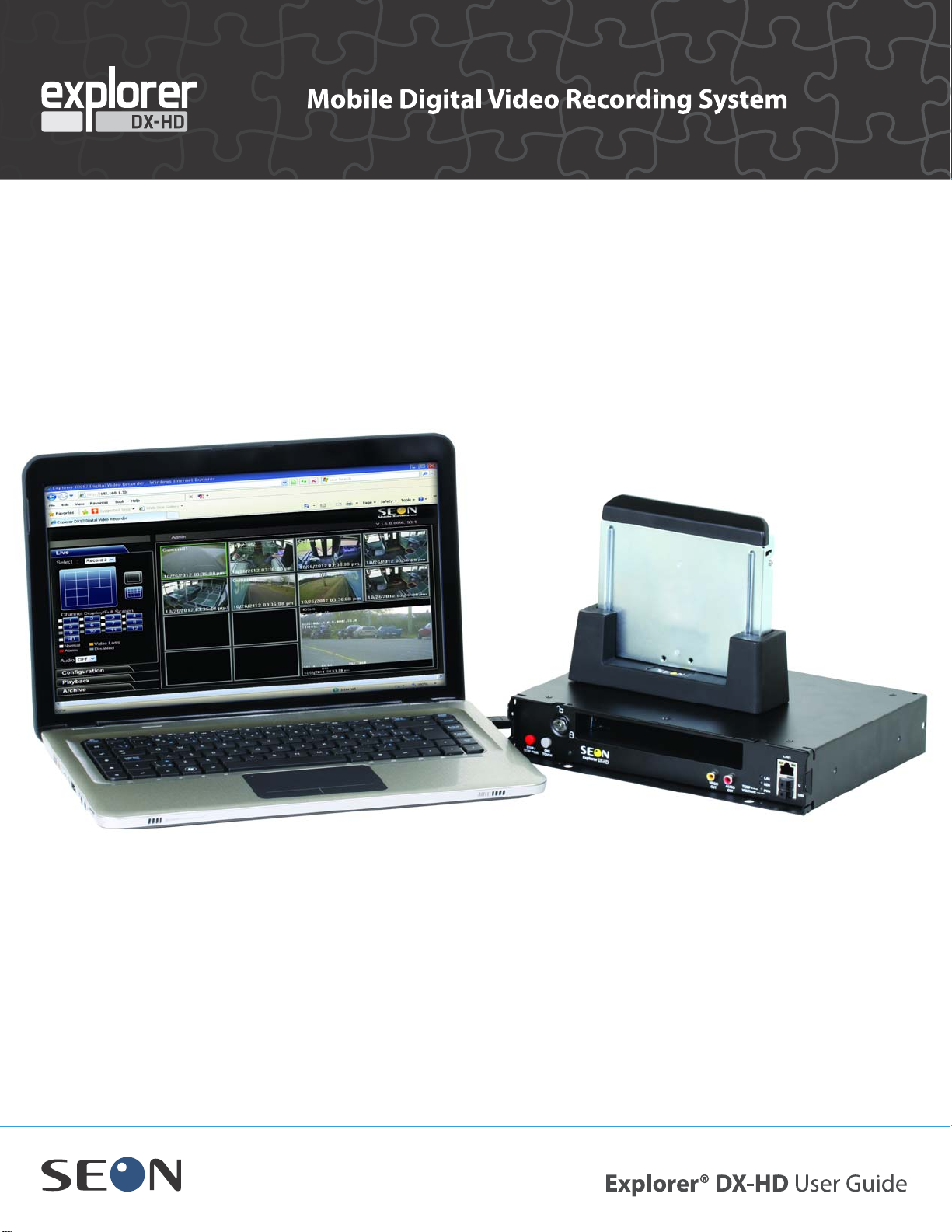
The User Guide is intended for anyone who needs to operate, configure, or troubleshoot the Explorer®
DX-HD Mobile Digital Video Recording (DVR) System. Related user guides include:
•Explorer DX-HD Install and Setup Guide, 700-0189
•vMax View User Guide, 700-0137
Conventions Used
Abbreviations and Acronyms
More Information at www.seon.com
You can find more information about Seon Design Inc. as well as its products and services at
www.seon.com.
CAUTION
Cautions identify conditions or practices that could result in damage to the unit or other equipment,
or data loss.
Recommendation: These notes provide tips for optimum performance of the DVR system.
Important: These notes provide important information, which are not as serious as a Caution.
Acronym Definition Acronym Definition
DVR Digital video recorder LAN Local area network
FPS Frames per second MJPEG Motion Joint Photographic Experts Group
GPS Global Positioning System OSD On-Screen Display
HD High Definition RA Return Authorization
HDD Hard disk drive TCP/IP Transmission Control Protocol/Internet Protocol
H.264 Video compression standard USB Universal Serial Bus
IPS Images per second UTC Universal Time Coordinated
IR Infrared

700-0117 R003 iii
Chapter 1 Introduction
1.1. Overview - - - - - - - - - - - - - - - - - - - - - - - - - - - - - - - - - - - - - - - - - - - - - - - - - - - - - - - - - - - - - - -1–1
1.2. DX-HD DVR Product Features- - - - - - - - - - - - - - - - - - - - - - - - - - - - - - - - - - - - - - - - - - - - - - - -1–2
1.2.1. DX-HD System Components - - - - - - - - - - - - - - - - - - - - - - - - - - - - - - - - - - - - - - - - - - - - - - - - - - - - -1–3
1.2.2. Recording Capacity for DVR Hard Drive Storage - - - - - - - - - - - - - - - - - - - - - - - - - - - - - - - - - - - - - - -1–3
1.2.3. Front Panel Features - - - - - - - - - - - - - - - - - - - - - - - - - - - - - - - - - - - - - - - - - - - - - - - - - - - - - - - - - - -1–3
1.2.4. Back Panel Features - - - - - - - - - - - - - - - - - - - - - - - - - - - - - - - - - - - - - - - - - - - - - - - - - - - - - - - - - - -1–5
1.2.5. Using the Trackball Mouse - - - - - - - - - - - - - - - - - - - - - - - - - - - - - - - - - - - - - - - - - - - - - - - - - - - - - - -1–6
1.3. DVR Video Configuration Playback and Archiving - - - - - - - - - - - - - - - - - - - - - - - - - - - - - - - - - -1–7
Chapter 2 DVR Operation
2.1. Remove and Replace the DVR Hard Drive - - - - - - - - - - - - - - - - - - - - - - - - - - - - - - - - - - - - - - -2–2
2.2. Search, Playback, and Archive Video - - - - - - - - - - - - - - - - - - - - - - - - - - - - - - - - - - - - - - - - - - -2–2
2.3. vMax View and HDD Dock- - - - - - - - - - - - - - - - - - - - - - - - - - - - - - - - - - - - - - - - - - - - - - - - - - -2–3
2.4. On-Screen Display Access - - - - - - - - - - - - - - - - - - - - - - - - - - - - - - - - - - - - - - - - - - - - - - - - - -2–4
2.4.1. Playback Menu Access - - - - - - - - - - - - - - - - - - - - - - - - - - - - - - - - - - - - - - - - - - - - - - - - - - - - - - - - -2–6
2.4.2. Using the Search Function - - - - - - - - - - - - - - - - - - - - - - - - - - - - - - - - - - - - - - - - - - - - - - - - - - - - - - -2–8
2.4.3. Using the Archive Function - - - - - - - - - - - - - - - - - - - - - - - - - - - - - - - - - - - - - - - - - - - - - - - - - - - - -2–11
2.4.4. Copy to USB - - - - - - - - - - - - - - - - - - - - - - - - - - - - - - - - - - - - - - - - - - - - - - - - - - - - - - - - - - - - - - -2–12
2.4.4.1. Archive Segmentation - - - - - - - - - - - - - - - - - - - - - - - - - - - - - - - - - - - - - - - - - - - - - - - - - - - -2–12
2.5. Using One-Touch Download - - - - - - - - - - - - - - - - - - - - - - - - - - - - - - - - - - - - - - - - - - - - - - - -2–13
Chapter 3 vMax Web Operation
3.1. System requirements - - - - - - - - - - - - - - - - - - - - - - - - - - - - - - - - - - - - - - - - - - - - - - - - - - - - - -3–1
3.2. Accessing vMax Web - - - - - - - - - - - - - - - - - - - - - - - - - - - - - - - - - - - - - - - - - - - - - - - - - - - - - -3–2
3.3. vMax Web User Interface - - - - - - - - - - - - - - - - - - - - - - - - - - - - - - - - - - - - - - - - - - - - - - - - - - -3–4
3.3.1. vMax Web Live Tab - - - - - - - - - - - - - - - - - - - - - - - - - - - - - - - - - - - - - - - - - - - - - - - - - - - - - - - - - - -3–5
3.3.2. vMax Web Configuration Tab - - - - - - - - - - - - - - - - - - - - - - - - - - - - - - - - - - - - - - - - - - - - - - - - - - - - -3–6
3.3.3. vMax Web Playback Tab - - - - - - - - - - - - - - - - - - - - - - - - - - - - - - - - - - - - - - - - - - - - - - - - - - - - - - - -3–7
3.3.3.1. Search Video from Time Point or Event Marker - - - - - - - - - - - - - - - - - - - - - - - - - - - - - - - - - - -3–9
3.3.1. vMax Web Archive Tab - - - - - - - - - - - - - - - - - - - - - - - - - - - - - - - - - - - - - - - - - - - - - - - - - - - - - - - -3–12
3.3.1.1. Archive Segmentation - - - - - - - - - - - - - - - - - - - - - - - - - - - - - - - - - - - - - - - - - - - - - - - - - - - -3–13
3.3.2. Viewing DX-HD Video Archives - - - - - - - - - - - - - - - - - - - - - - - - - - - - - - - - - - - - - - - - - - - - - - - - - -3–13
Chapter 4 DVR Firmware and Configuration Uploads
4.1. Firmware Updates- - - - - - - - - - - - - - - - - - - - - - - - - - - - - - - - - - - - - - - - - - - - - - - - - - - - - - - - -4–2
4.2. Configuration Uploads- - - - - - - - - - - - - - - - - - - - - - - - - - - - - - - - - - - - - - - - - - - - - - - - - - - - - -4–3
4.2.1. USB Memory Device to DVR Configuration Upload - - - - - - - - - - - - - - - - - - - - - - - - - - - - - - - - - - - - -4–3
4.2.2. Uploading Configuration Files to DVR via vMax Web - - - - - - - - - - - - - - - - - - - - - - - - - - - - - - - - - - - -4–7
Contents

Contents
iv 700-0117 R003
Chapter 5 Maintenance, Troubleshooting, and Service
5.1. Maintenance Tasks - - - - - - - - - - - - - - - - - - - - - - - - - - - - - - - - - - - - - - - - - - - - - - - - - - - - - - - 5–1
5.2. Troubleshooting the DX-HD - - - - - - - - - - - - - - - - - - - - - - - - - - - - - - - - - - - - - - - - - - - - - - - - - 5–2
5.3. Returning Product for Service - - - - - - - - - - - - - - - - - - - - - - - - - - - - - - - - - - - - - - - - - - - - - - - - 5–3
Appendix A Specifications
A.1. Explorer DX-HD - - - - - - - - - - - - - - - - - - - - - - - - - - - - - - - - - - - - - - - - - - - - - - - - - - - - - - - - - A–1
A.1.1. Advanced Smart-Temp™ - - - - - - - - - - - - - - - - - - - - - - - - - - - - - - - - - - - - - - - - - - - - - - - - - - - - - - - A–2
A.1.2. Explorer DX-HD Functional Features - - - - - - - - - - - - - - - - - - - - - - - - - - - - - - - - - - - - - - - - - - - - - - - A–2
A.1.3. Explorer DX-HD Front Cover, Cable Cover - - - - - - - - - - - - - - - - - - - - - - - - - - - - - - - - - - - - - - - - - - A–2
A.1.4. Smart-Link™ Module - - - - - - - - - - - - - - - - - - - - - - - - - - - - - - - - - - - - - - - - - - - - - - - - - - - - - - - - - - A–2
Legal Notice
Seon Design® Inc. - - - - - - - - - - - - - - - - - - - - - - - - - - - - - - - - - - - - - - - - - - - - - - - - - - - - - - - - - - - L–1
Contact Information - - - - - - - - - - - - - - - - - - - - - - - - - - - - - - - - - - - - - - - - - - - - - - - - - - - - - - - - - - L–1
Seon Design Inc.® Product Warranty
Advance Replacements - - - - - - - - - - - - - - - - - - - - - - - - - - - - - - - - - - - - - - - - - - - - - - - - - - - - - - -W–1
Disclaimer - - - - - - - - - - - - - - - - - - - - - - - - - - - - - - - - - - - - - - - - - - - - - - - - - - - - - - - - - - - - - - - - -W–2

Introduction
700-0190 R003 1–1
CHAPTER 1
Introduction
This chapter contains the following sections:
Overview, on page 1–1
DX-HD DVR Product Features, on page 1–2
DVR Video Configuration Playback and Archiving, on page 1–7
DX-HD System Components, on page 1–3
Recording Capacity for DVR Hard Drive Storage, on page 1–3
Front Panel Features, on page 1–3
Back Panel Features, on page 1–5
Using the Trackball Mouse, on page 1–6
DVR Video Configuration Playback and Archiving, on page 1–7
1.1. Overview
This section introduces the product features of the Explorer DX-HD Plus Mobile Digital Video
Recording (DVR) System.
The DX-HD DVR integrates with the optional Smart-Reach wireless and cellular technology and
works with optional vMax Commander and vMax View video management software for on-board
video data management.

Introduction
1–2 700-0190 R003
1.2. DX-HD DVR Product Features
The Explorer DX-HD has the following product features:
• supports up to 12 video channels and 12 audio channels
• has one high-definition video channel at 1280 × 720 pixel resolution
• records up to 30 frames per second (FPS) at 720 × 480 D1 resolution on all video channels
simultaneously
• offers H.264 and MJPEG video compression for enhanced compression and quality
• has removable dual HDD cartridge
• stores up to 2.0 TeraBytes (TB)
• offers dual stream recording; high-resolution stream for playback on a PC, and a lower resolution
stream for viewing over a cellular phone network
• DVR Health Check monitors DVR and hard drive status and notifies the administrator of any
issues, ensuring all onboard events are captured, using the vMax Commander video management
software Health Check feature
• uses Global Positioning System (GPS) technology for Geo-fencing, to designate a geographic
boundary for the vehicle and provides an alert if the vehicle leaves the area
• uses G Sensor technology to provide driver behavior and accident impact velocity data
• keyed access to front cover and secure cable cover with slotted cable entries to restrict access to
authorized personnel, see Figure 1-1
• configure, playback, and archive video from the DVR locally with trackball mouse, monitor, and
DVR On Screen Display (OSD) and USB memory stick
• configure, playback, and archive video from the DVR remotely with vMax Web via Wi-fi network
or Ethernet connection
• interfaces with network using RJ-45 connections on the front and back panels, see Figure 1-2 and
Figure 1-3.
• mounting options that can accommodate horizontal or vertical installation
Figure 1-1
DX-HD DVR with Security Front Cover and Secure Cable Cover

Introduction
700-0190 R003 1–3
1.2.1. DX-HD System Components
A typical DX-HD Plus system has the following components (see DVR Video Configuration Playback
and Archiving, on page 1–7):
• Explorer DX-HD DVR and DVR drive with dual HDD cartridge
• Cameras and camera cables, one connector per camera
• Smart-Link™ module and cables and wiring harnesses
• HD camera, optional
• Diagnostic Button, optional
• Smart-Reach Lite wireless bridge, optional
• Speed harness, optional
• GPS receiver, optional
• HDD Dock, optional
• Trackball mouse and portable monitor for navigating on-screen display, optional
1.2.2. Recording Capacity for DVR Hard Drive Storage
The DX-HD DVR uses H.264 video compression to maximize the recording time on the dual HDD
cartridge. The amount of recorded video varies, depending on the FPS, resolution (horizontal x vertical
pixel count), and number of cameras being recorded, and picture quality settings. Lower picture
quality results in higher compression and a lower memory requirement. Higher picture quality results
in lower compression and a higher memory requirement.
1.5 TB and 2 TB cartridges are also available.
\
1.2.3. Front Panel Features
Figure 1-2 shows the front panel features followed by a short description in Table 1-1.
Figure 1-2
DX-HD DVR Front Panel
1 2 3
45678910

Introduction
1–4 700-0190 R003
Table 1-1
DX-HD DVR Front Panel Feature Descriptions
Feature Description Item
Controls DVR drive lock Requires the dual HDD cartridge key to unlock and remove the dual HDD
cartridge.
When the DVR is recording, turn the hard drive key to the open position.
The DVR HDD Activity LED blinks while the recordings are stopping.
After ten seconds or until the red HDD activity indicator is off, gently pull
out the hard drive.
CAUTION: Data Loss
Do not remove the dual HDD cartridge until 10 seconds after power to the
hard drive is turned off and the red HDD activity indicator is off. Failure to
do so may result in lost data.
1
Dual HDD cartridge Remove the dual HDD cartridge to a separate location for playback using
the HDD Dock connected to a PC or laptop. See Remove and Replace the
DVR Hard Drive, on page 2–2.
2
ONE TOUCH Press to start one touch downloading to a USB memory device in a USB
port. See Using One-Touch Download, on page 2–13.
9
STOP/TEMP PWR • Powers on the DVR for five minutes, when held for more than 5
seconds.
• Powers down the DVR if held for more than 5 seconds when the DVR
is in temporary power mode, or in shutdown sequence and ignition is
off.
• Press the STOP button to temporarily stop the DVR from recording or
playing.
10
Connections LAN1 Ethernet port with RJ-45 connector for connecting to the local area network
(LAN). Ethernet is used to connect either to a PC, laptop, or directly to the
Smart-Reach wireless bridge or other equipment.
3
USB1, USB2 ports
(supporting USB 2.0)
Supports USB devices for:
• Copying video and audio information.
• Exporting video clips.
• Updating the DVR firmware.
• Connecting the trackball/mouse.
4
AUDIO OUT (red) RCA jack, for listening to live or recorded audio from the camera
microphones.
6
VIDEO OUT
(yellow)
RCA jack for DVR configuration, troubleshooting, video playback, live
viewing with portable monitor and mouse.
7
Indicators LAN (green) Illuminates when there is network activity on the LAN connection. 5
HDD (red) Illuminates when the DVR is accessing the dual HDD cartridge.
PWR (green LED)
TEMP
VOLTAGE
• Illuminates when the DVR is powered on.
• Flashes quickly when the DVR cannot power up due to temperature
limitations.
• Flashes slowly when the DVR cannot power up due to voltage
limitations.
Introduction
700-0190 R003 1–5
1.2.4. Back Panel Features
Figure 1-3 shows the back panel features followed by a short a description.
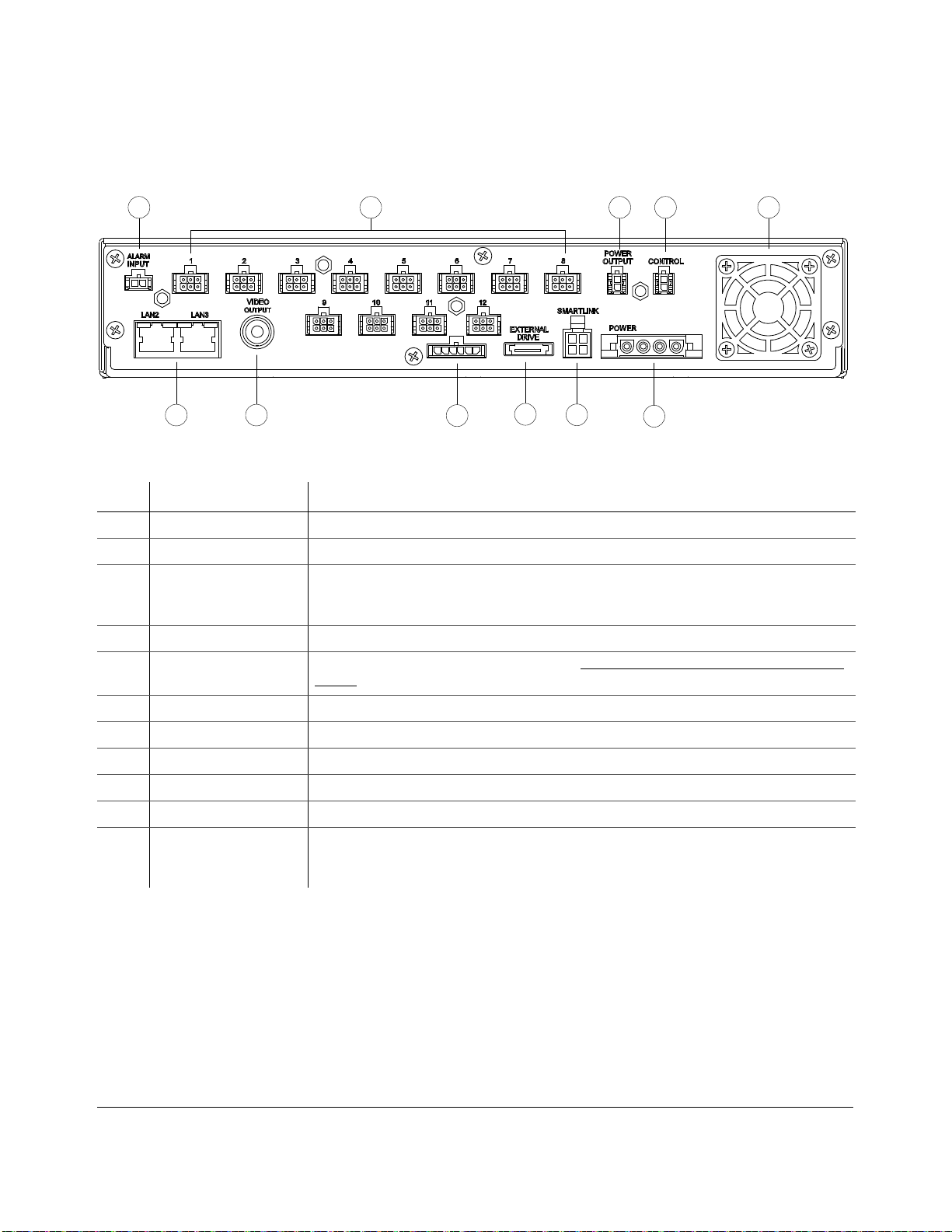
Figure 1-3
Back Panel Features
Item Feature Description
1 ALARM INPUT Alarm input connector for the alarm button.
2 1 to 12 Twelve camera input connectors.
3 POWER OUTPUT Auxiliary power connector. Used to supply DVR power to the HD Camera using the HD
Camera connector cable 060-0670. Turns off after recording as configured in delay settings. See
the DX-HD DVR Installation Guide 700-0189 for details.
4 CONTROL Control connector for controlling the Smart-Reach Mobile wireless bridge equipment.
5 Fan Intake fan with filter and removable cover. See Chapter 5, Maintenance, Troubleshooting, and
Service.
6 POWER Power input connector for connecting the power harness.
7 SMART-LINK Smart-Link connector.
8 Do not use For Seon use only.
9 Do not use For Seon use only.
10 VIDEO OUTPUT Configurable video output for viewing video, BNC connector
11 LAN2, LAN3 Ethernet ports with RJ-45 connector for connecting an HD camera or to LAN. Ethernet is used
to connect either to a PC or laptop or directly to the Smart-Reach wireless bridge or other
equipment.
1 2 3 4 5
6
7
1011 98

Introduction
1–6 700-0190 R003
1.2.5. Using the Trackball Mouse
Figure 1-4 shows the buttons on the trackball mouse followed by a description of the features.
Many other USB mice will also work with the DVR.
Figure 1-4
Trackball Mouse
To do this… Use
Select the highlighted menu option by pressing the middle button. 1
Select the highlighted menu option by pressing the left button with your thumb. 2
• Delete a character entered into a field or go back to a previous items by pressing the button on the right.
• Press the right button to enter the configuration menu.
3
Move the cursor around the screen by rotating the blue button. 4
1
2
3
4

Introduction
700-0190 R003 1–7
1.3. DVR Video Configuration Playback and Archiving
Here is an introductory overview of the configuration, playback, and archiving methods available on
the DX-HD.
The DX-HD DVR content can be accessed and archived in four ways:
• locally via OSD, mouse, and portable video monitor. See DVR Operation, on page 2–1.
• Locally via One Touch button and USB memory device. See Using One-Touch Download, on
page 2–13.
• remotely via vMax Web browser interface and Ethernet/wireless connection.
See vMax Web Operation, on page 3–1.
• via vMax View video management software and dual HDD cartridge interface.
See vMax View and HDD Dock, on page 2–3. See also:
Explorer DX-HD Installation Guide, 700-0199
vMax Commander Software User Guide, 700-0120
vMax View User Guide, 700-0137
The following table shows which methods support video configuration, playback, and archiving.
To do this… Use...
On-screen display
with monitor and
trackball mouse
vMax Web access
with Internet
Explorer
DVR HDD Dock
& vMax View
software
Configure the DVR menu settings.
Playback and view recorded video with single channel view
or multiple views.
Playback recorded HD camera video in single channel view
or with multiple views.
x
Search for video from a Segment, an Events list, or by time
and date.
Archive video to .avr file format.
Archive low resolution (Record2) video stream
Archiving options — each individual channel can be
archived as a .avi file and individual images saved as .bmp
or .jpg files

Introduction
1–8 700-0190 R003

DVR Operation
700-0190 R003 2–1
CHAPTER 2
DVR Operation
This chapter provides information on using the DX-HD DVR, and viewing recorded video. This
chapter contains the following sections:
Remove and Replace the DVR Hard Drive, on page 2–2
Search, Playback, and Archive Video, on page 2–2
vMax View and HDD Dock, on page 2–3
On-Screen Display Access, on page 2–4
Playback Menu Access, on page 2–6
Using the Search Function, on page 2–8
Using the Archive Function, on page 2–11
Copy to USB, on page 2–12
Using One-Touch Download, on page 2–13

DVR Operation
2–2 700-0190 R003
2.1. Remove and Replace the DVR Hard Drive
The DVR has two hard drives contained in a single removable cartridge. A dual HDD cartridge lock
secures the hard drive during operation. Use the hard drive key to lock and unlock the dual HDD
cartridge.
To remove the dual HDD cartridge:
1. Insert the dual HDD cartridge key.
2. Turn the key counter clockwise by ¼ turn until the hard drive lock is in the unlocked position.
3. After the red HDD LED is off, gently pull out the dual HDD cartridge.
To replace the dual HDD cartridge:
1. Slide in a dual HDD cartridge until the hard drive seats inside the front panel.
2. Insert the dual HDD cartridge key, turn clockwise by ¼ turn until the hard drive lock is in the
locked position.
2.2. Search, Playback, and Archive Video
The HD camera output is visible from vMax Web and vMax View, but not in the DVR on screen
monitor view.
To search, playback, and archive recorded video, use one of four methods:
vMax View and HDD Dock
Remove the dual HDD cartridge from the DVR, and use the HDD Dock and vMax View software. See
vMax View and HDD Dock, on page 2–3.
On Screen Display Menus
For local video access, connect a portable video monitor to the DX12 DVR video out jack. Use the
trackball mouse to navigate the OSD menus. See Using the Search Function, on page 2–8.
vMax Web Menus
For local or remote video access, use a laptop and the vMax Web browser user interface with Ethernet or
Wi-fi connectivity. Video recorded with the HD camera is only available for playback via vMax Web if
the DVR’s Ethernet port is connected to a network. See vMax Web Operation, on page 3–1.
One Touch Button and USB memory Device
For quick download of flagged video, use the One Touch Button and a USB memory device. See
Using One-Touch Download, on page 2–13 for instructions.
CAUTION: Data Loss Risk
Do not remove the dual HDD cartridge until the red HDD activity indicator is off. Failure to do
so may result in lost data. While the dual HDD cartridge is hot swappable (the dual HDD
cartridge can be removed when the DVR is powered up), do not remove the dual HDD
cartridge while the DVR is recording, as the video segment may not be recorded.
CAUTION: Hard Drive Identification
Notice that the DX-HD hard drive has an identifying label to identify it as for this DVR series. Placing the
DX-HD hard drive in a DX12 DVR and vice versa will result in lost data.

DVR Operation
700-0190 R003 2–3
2.3. vMax View and HDD Dock
The HDD Dock is provided with vMax View software to accommodate the DX-HD drive. The HDD
Dock uses AC power and a USB3 connector to the PC.
To access video from the drive using vMax View:
1. Connect the AC adapter to the HDD Dock socket.
2. Connect the AC adapter to an AC power outlet.
3. Connect the USB cable to a PC socket.
4. Power on the HDD Dock using the button between the USB and AC cable connectors.
5. Remove the drive from the DVR.
6. Insert the DX-HD DVR hard drive into the HDD Dock as shown.
7. On the PC, launch vMax View and search the drive for the required video to archive. See vMax
View User Guide 700-0137 for detailed procedures.
Figure 2-1
DX12 Hard Drive Interface with Hard Drive
DX-HD ONL
Y
DVR Operation
2–4 700-0190 R003
2.4. On-Screen Display Access
Use the On-Screen Display mode to locally access the dual HDD cartridge content.
To use the on-screen display (OSD) with trackball mouse and monitor:
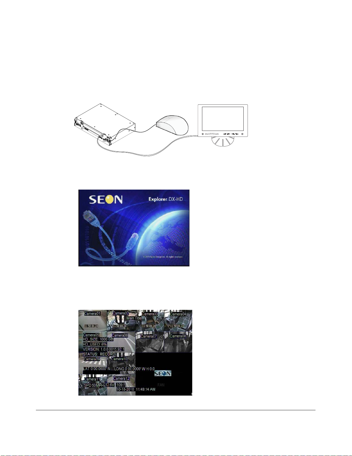
1. Connect a portable video monitor to the VIDEO OUT RCA jack on the DX-HD front panel.
Plug the USB trackball or mouse in a USB socket on the front of the DVR.
When the DVR starts up, the Seon Explorer DX-HD splash screen (see Figure 2-3) appears briefly
before the DVR enters live view.
During recording and live viewing, the screen information is dynamic and can include the items
shown in Figure 2-4 and described in Table 2-1. The screen items can be configured in the main
menu.
Figure 2-2
Mouse and Monitor Connected to DVR
Portable
Video Monitor
DX-HD DVR
USB Mouse
Figure 2-3
DX-HD Splash Screen
Figure 2-4
On-Screen Display during Live Viewing and Recording

DVR Operation
700-0190 R003 2–5
2. Use the trackball mouse (right-click) to access the DVR’s configuration, playback, and archiving
menu settings as required.
3. Proceed to the Configuration or Operation and Playback chapters for details on available setting
options.
Table 2-1
On-Screen Display Information
Feature Description
Camera 1 to Camera 12 Camera titles, maximum 8 characters each.
Main_Title Main title of the DVR, maximum 32 characters.
HD_Size Formatted size of the dual HDD cartridge, in gigabytes (GB).
HD_Used Percentage of recorded video on the dual HDD cartridge. At 100%, the message displayed
depends on the Repeat Record settings in the Recording Settings menu.
• When Repeat Record is set to On, the HD Used message reads “N/A Repeating”. N/A
means that information on how much of the hard drive space is used is not available
because the hard drive is full. Repeating means the DVR continues recording,
overwriting the oldest recorded data.
• When Repeat Record is set to Off, the HD Used message reads “100%”. The DVR
stops recording.
Camera Off Indicates how long the cameras will record after the DVR powers down. Configured as
Record Delay-Off time from 0 seconds to 30 minutes
Version DVR firmware version. To update, see Firmware Updates, on page 4–2.
Status DVR operation status:
• LIVE (live mode not recording)
• PLAYBACK (the DVR is playing locally, displays RECORD, ALARM or TIMER)
• RECORD (normal recording)
• ALARM (alarm recording)
• TIMER (timer recording)
• V. LOSS (video loss or camera signal loss)
Speed Display Vehicle speed and units (MPH, KPH).
Voltage System voltage from 8 to 32 VDC.
Temperature DVR temperature in degrees Fahrenheit or Celsius.
GPS When GPS display is enabled in the menus and the receiver is installed, the vehicle’s
latitude and longitude is displayed.
Time and Date Current/recorded time and date.
AC (Alarm count) Count of alarm(s) triggered. Resets to 0 when the DVR is restarted.
DVR Operation
2–6 700-0190 R003
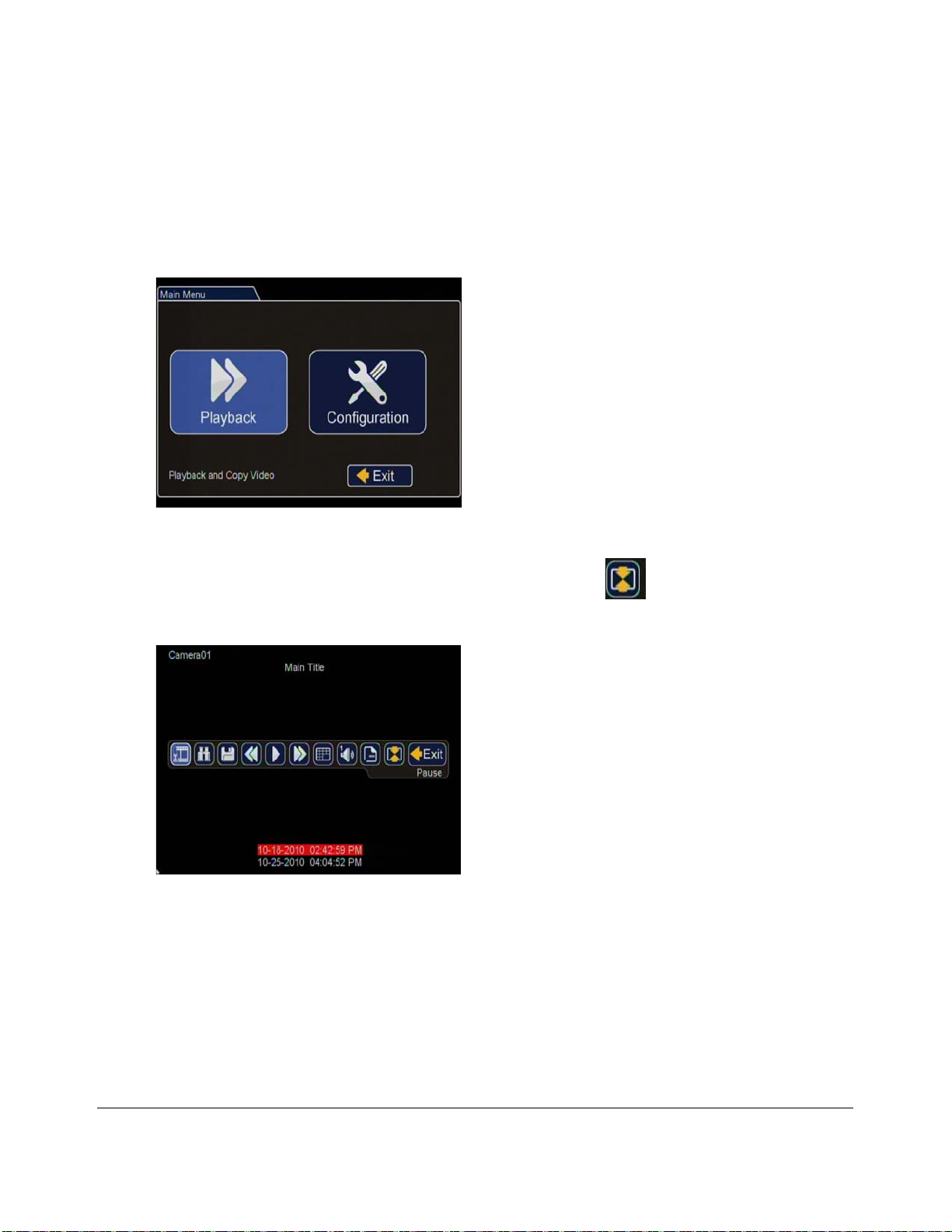
2.4.1. Playback Menu Access
Use the Playback menu to search, playback, and archive video directly from the DVR
hard drive.
To access the playback menu from the OSD:
1. In the OSD view, right-click the live view to access the Main Menu and click Playback.
2. In the middle of the screen click the Show/Hide Toolbar icon .
The Playback Toolbar appears.
Figure 2-5
Main Menu > Playback
Figure 2-6
Playback Toolbar Screen
DVR Operation
700-0190 R003 2–7
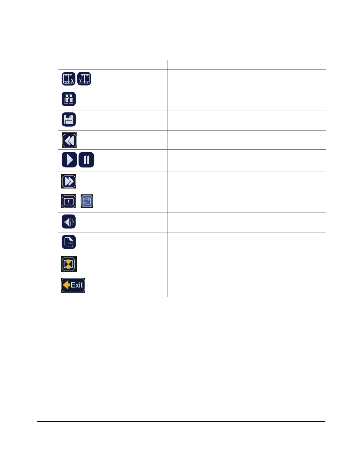
Table 2-2
Playback Toolbar Items
Toolbar Icon Description
Start of clip/End of clip Click to set the start of clip and end of clip points for one-touch
download.
Search Click to search by date, time or by Time, Alarm, Signals, or System
Event. See Figure 2-7 and Figure 2-8.
Archive Click to display Archive screen to copy a video clip to a USB memory
device.
Rewind • Click to reverse during playback 1, 2, 4, 8, 16, or 32×.
• With playback paused, each click reverses the video by one frame.
Play/Pause Click to start playback.
Click again to pause playback.
Fast Forward • Click to fast forward during playback 1, 2, 4, 8, 16, or 32×.
• With playback paused, each click advances the video by one frame.
Individual camera/16-up
mode
Click to display Camera 1 to 13 or 16-up mode.
Audio Click to cycle through Audio channels 1 to 13.
Metadata Text overlay Click to show or hide the text overlay such as temperature, system
voltage, GPS data (if recorded), speed, date, and time. These items can
be set in the Title/Display menu or Diagnostic Display sub-menu.
Show/Hide Playback toolbar Click to show or hide the playback toolbar.
Exit Click to exit to on-screen display.
1

DVR Operation
2–8 700-0190 R003
2.4.2. Using the Search Function
The DX-HD includes a powerful search function that lets you quickly find recorded information by
Date and Time, Alarm, Signals, or System Events.
To view the search menu:
1. From the playback tool bar, click on the Search icon. to display the Search menu.
The items appearing in the dialog box will depend on the item selected in Search Only box.
Figure 2-7
Search Menu
Table 2-3
Search Configuration Items
Menu Item Description Value [Default]
Start Date Set the start date for the search.
Time Set the start time for the search.
Search Only Select the desired search type. • [Time]
•Alarm •Alm0, Alm1, Alm2, Alm3, Alm4, All
• Signals • Signal 1 - Signal 10, All
• System
Event
•GPS
• Ignition
• Recording
•Timers
•Video Loss
• G Sensor
•Speed
•All
Search Press Enter to Start Search.
Other manuals for Explorer DX-HD
1
Table of contents
Other SEON Security System manuals

Popular Security System manuals by other brands

Audiovox
Audiovox AA-930 Installation & operation manual

Develco
Develco PBTZB-110 Technical manual

Geuterbrueck
Geuterbrueck G-ST 500+ Instructions for use

Seres OL
Seres OL OPAL Operation & maintenance manual

NuTone
NuTone la600wh Installation & operating instructions

Honeywell Home
Honeywell Home Ademco Vista Series quick guide


