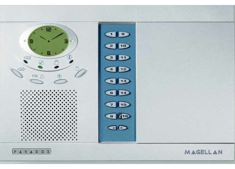
Magellan MG-6060 Operating instructions

All-In-One Wireless Security System V1.3
Programming Guide
Model # MG-6060 / MG-6030
Table of Contents
Things You Should Know ..................................... 2
About This Programming Guide........................................... 2
Conventions......................................................................... 2
Installer Code (Default: 0000 / 000000)............................... 2
Maintenance Code (Default: 1111 / 111111)....................... 2
Master Code (Default: 1234 / 123456)................................. 2
Decimal and Hexadecimal Values ....................................... 2
Entering Programming Mode ............................... 3
Single Digit Data Entry Method............................................ 3
Feature Select Programming Method .................................. 3
Installer Quick Keys .............................................. 3
Zone Programming................................................ 3
Wireless Transmitter Programming..................... 4
System Timers ....................................................... 4
On-board Programmable Outputs (PGMs) .......... 5
System Options ..................................................... 5
Communicator Settings ....................................... 8
Report Codes ......................................................... 9
Remote Control Button Programming ............... 10
System Settings ................................................... 11
Wireless Programmable Output (PGM) Settings 12
Appendix 1: PGM Event Table ............................ 12
Appendix 2: Specifications ................................. 15
Appendix 3: Connection Diagrams..................... 15
Power Connections ........................................................... 15
Telephone Line Connections ............................................ 16
PGM Connections ............................................................. 17
Hardwire Zone Connections.............................................. 18
Connecting the Radio Antenna (MG-6060 only) ............... 18
Connecting to a UIP-256................................................... 19
X10 Transmitter Connections (MG-6060 only).................. 19
Connecting Magellan to WinLoad ..................................... 20
Connecting a Paradox Memory Key (PMC-3)................... 20
Tabletop Mounting ............................................................ 21
Mounting Magellan on the Wall ......................................... 21
Appendix 4:
Ademco Contact ID Report Code List ................ 22
Appendix 5: Automatic Report Code List .......... 24

2Programming Guide
Things You Should Know
About This Programming Guide
This programming guide should be used in conjunction with the Magellan Reference & Installation Manual which can be downloaded
from our website at www.paradox.ca. Use this guide to record the settings programmed for this console.
Conventions
Installer Code (Default: 0000 / 000000)
The Installer code is used to enter programming mode (see Entering Programming Mode on page 3), which allows you to program all the
features, options and commands of the Magellan console except user codes. The Installer code can be 4 or 6 digits in length (see section
[090] option [1] on page 5) where each digit can be any value from 0 to 9. See section [181] on page 11 to change the default code.
Maintenance Code (Default: 1111 / 111111)
The Maintenance code is similar to the Installer code. It can be used to enter programming mode (see Entering Programming Mode
on page 3), which allows you to program all the features, options and commands except for the Magellan console’s communication
settings (sections [100] to [154]) as well as any user codes. The Maintenance code can be 4 or 6 digits in length (see section [090]
option [1] on page 5) where each digit can be any value from 0 to 9. See section [182] on page 11 to change the default code.
Master Code (Default: 1234 / 123456)
With the System Master code a user can use any arming method and can program user codes. The System Master code can be 4 or
6 digits in length (see section [090] option [1] on page 5), where each digit can be any digit from 0 to 9. The System Master code
cannot be changed by the Installer or Maintenance code, but it can be reset to default. See section [200] on page 11 to reset to default.
Decimal and Hexadecimal Values
Figure 1: Decimal and Hexadecimal Values
This symbol designates a warning or important information.
This symbol designates a suggestion or reminder.
This symbol designates a reference to another section, manual or guide.
This symbol designates a feature that can also be programmed in the Installer menu which can be accessed by pressing
[menu] and then entering your [
INSTALLER
CODE
]. The icon will then be followed by the path or buttons that have to be
pressed in order to access the feature once in the Installer menu. For example:
= Once in the Installer menu, press the [4] key and then press the [6] key to access the desired feature.
Refer to the Installer Menu Overview on the back cover for more information on accessing and using the Installer menu.
J[4] J[6]
Decimal and
Hexadecimal
Values:
Keys [0] to [9] = 0
to 9
Hexadecimal only
values:
[1] = A
[2] = B
[3] = C
[4] = D
[5] = E
[6] = F

Magellan 3
Entering Programming Mode
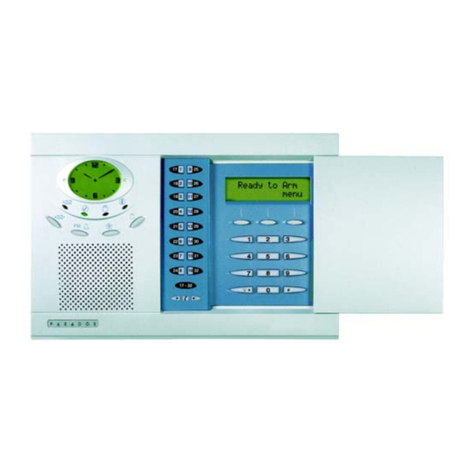
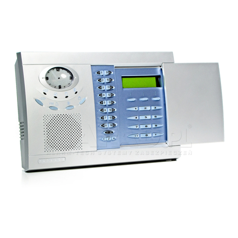
Use the built-in keypad to access Magellan’s installer programming mode. To access programming mode:
1. Press and hold the [0] key.
2. Enter your [
INSTALLER
CODE
]or [
MAINTENANCE
CODE
].
3. Enter the 3-digit [
SECTION
]you wish to program.
4. Enter the required [
DATA
].
5. Press the [*] key to clear data or to go back one step. Press the [#] key to save changes.
There are two methods that can be used to enter data when in programming mode: Single Digit Data Entry and Feature Select
Programming methods.
Single Digit Data Entry Method
After entering programming mode, some sections will require that you enter decimal values from 000 to 255. Other sections will
require that you enter hexadecimal values from 0 to F. The required data will be clearly indicated in this manual. When entering the
final digit in a section, Magellan will automatically save and advance to the next section. Refer to Figure 1 on page 2 to see the keys
and their equivalent decimal and/or hexadecimal value.
Feature Select Programming Method
After entering certain sections, eight options will be displayed where each option from [1] to [8] represents a specific feature. Press
the key corresponding to the desired option and the option number will appear in the LCD screen. This means the option is ON.
Press the key again to remove the digit from the LCD screen (a *appears), thereby, turning OFF the option. Press the [*] key to set
all eight options to OFF. When the options are set, press the [#] key to save and advance to the next section.
Installer Quick Keys
To access the Installer Quick keys, press and hold the [0] key from the Main keypad, enter the [
INSTALLER
CODE
]and then press from the
Center keypad:
Key [1] = Test Report: Send the “Test Report” report code programmed in section [155] (page 10) to the monitoring station.
Key [2] = Cancel Communication: Cancels all communication with the WinLoad software or with the monitoring station until the next reportable event.
Key [3] = Answer WinLoad Software: Will force the console to answer an incoming call from the monitoring station that is using the WinLoad software.
Key [4] = Call WinLoad Software: Will dial the PC telephone number programmed in section [118] (page 8) in order to initiate communication with a
computer using the WinLoad software.
Key [5] = Installer Test Mode: The installer test mode will allow you to perform walk tests where the siren will squawk to indicate opened zones. Press the
[5] key again to exit.
Zone Programming
Section Description Zone Definition Zone Options Section Description Zone Definition Zone Options
[001]
Zone 1:__________
____/____/____ 1 2 3 4 5 6 7 8 [009]
Zone 9:__________
____/____/____ 1 2 3 4 5 6 7 8
[002]
Zone 2:__________
____/____/____ 1 2 3 4 5 6 7 8 [010]
Zone 10:_________
____/____/____ 1 2 3 4 5 6 7 8
[003]
Zone 3:__________
____/____/____ 1 2 3 4 5 6 7 8 [011]
Zone 11_________
____/____/____ 1 2 3 4 5 6 7 8
[004]
Zone 4:__________
____/____/____ 1 2 3 4 5 6 7 8 [012]
Zone 12:_________
____/____/____ 1 2 3 4 5 6 7 8
[005]
Zone 5:__________
____/____/____ 1 2 3 4 5 6 7 8 [013]
Zone 13:_________
____/____/____ 1 2 3 4 5 6 7 8
[006]
Zone 6:__________
____/____/____ 1 2 3 4 5 6 7 8 [014]
Zone 14:_________
____/____/____ 1 2 3 4 5 6 7 8
[007]
Zone 7:__________
____/____/____ 1 2 3 4 5 6 7 8 [015]
Zone 15:_________
____/____/____ 1 2 3 4 5 6 7 8
[008]
Zone 8:__________
____/____/____ 1 2 3 4 5 6 7 8 [016]
Zone 16:_________
____/____/____ 1 2 3 4 5 6 7 8
Zone Definitions ( )
000 = Zone Disabled (default)
001 = Entry Delay 1
002 = Entry Delay 2
003 = Follow Zone
004 = Follow / Stay Zone
005 = Instant Zone
006 = Instant / Stay Zone
007 = Instant Fire Zone
008 = Delayed Fire Zone
009 = 24Hr. Burglary Zone
010 = 24Hr. Hold-up Zone
011 = 24Hr. Buzzer Zone
012 = 24Hr. Gas Zone
013 = 24Hr. Heat Zone
014 = 24Hr. Water Zone
015 = 24Hr. Freeze Zone
J[4] J[6] Zone Options
[1] = Auto-zone Shutdown (default)
[2] = Bypassable Zone (default)
[3] = Future Use
[6] = Intellizone
[7] = Delay alarm transmission
[8] = Force Zone (default)
† Intellizone is not for use in UL
installations.
‡ Force Arming is not permitted in UL
installations.
[4] [5] Zone Alarm Type
OFF OFF
Audible alarm (default)
OFF ON Pulsed alarm
ON OFF Silent alarm
ON ON Report only

4Programming Guide
Wireless Transmitter Programming
In the desired zone’s corresponding section, assign the transmitter’s serial number. In sections [058] and [059], assign the 6-digit serial
number of the transmitter that you are using as a wireless doorbell. You can also use these sections to view transmitter signal strength.
System Timers
*000 = No tone; 001 = Beeping; 002 = Countdown; 003 = Tonality 1; 004 = Tonality 2; 005 = Tonality 3; 006 = Tonality 4;
007 = Radio tuner (MG-6060 only)
Section Serial Number Section Serial Number
[021]
Zone 1: ____/____/____/____/____/____
[029]
Zone 9: ____/____/____/____/____/____
[022]
Zone 2: ____/____/____/____/____/____
[030]
Zone 10: ____/____/____/____/____/____
[023]
Zone 3: ____/____/____/____/____/____
[031]
Zone 11: ____/____/____/____/____/____
[024]
Zone 4: ____/____/____/____/____/____
[032]
Zone 12: ____/____/____/____/____/____
[025]
Zone 5: ____/____/____/____/____/____
[033]
Zone 13: ____/____/____/____/____/____
[026]
Zone 6: ____/____/____/____/____/____
[034]
Zone 14: ____/____/____/____/____/____
[027]
Zone 7: ____/____/____/____/____/____
[035]
Zone 15: ____/____/____/____/____/____
[028]
Zone 8: ____/____/____/____/____/____
[036]
Zone 16: ____/____/____/____/____/____
[037] to [057]
Future use
[058]
Wireless Doorbell 1: ____/____/____/____/____/____
[059]
Wireless Doorbell 2: ____/____/____/____/____/____
Section Data (value from 000 to 255) Description Defaults
[060]
____/____/____ seconds
Entry delay 1 (
)†
045 secs.
[061]
____/____/____ seconds
Entry delay 2 (
)†
045 secs.
[062]
____/____/____ seconds
Exit delay (
)‡
060 secs.
[063]
____/____/____ minutes
Bell cut-off time (
) *
004 mins.
[064]
____/____/____ x 15 minutes
No movement time Disabled
[065]
____/____/____ seconds (minimum 10 seconds)
Intellizone delay 045 secs.
[066]
____/____/____ seconds
Recent closing delay Disabled
[067]
____/____/____ times
Auto-zone shutdown 005 times
[068]
____/____/____ seconds
PGM1 timer Disabled
[069]
____/____/____ seconds
PGM2 timer Disabled
[070]
____/____/____ minutes
Power failure report delay 015 mins.
[071]
____/____/____ days
Auto-test report Disabled
[072]
____/____/____ rings
Number of rings 008 rings
[073]
____/____/____ seconds
TLM fail timer 032 secs.
[074]
____/____/____ seconds
Answering machine override delay 030 secs.
[075]
____/____/____ seconds
Delay alarm transmission Disabled
[076]
____/____/____ seconds (maximum 130 seconds)
Delay between dialing attempts
V
020 secs.
[077]
____/____/____ seconds
Pager/voice delay 005 secs.
[078]
____/____/____ seconds
Remote panic disarm lock delay 020 secs.
[079]
____/____/____ repetitions
Voice reporting message repetitions 003 reps.
[080]
____/____/____ days
Closing delinquency delay Disabled
[081]
____/____/____ (000 to 007*)
Entry delay audio selection
()
003
[082]
____/____/____ (000 to 007*)
Exit delay audio selection
()
002
[083]
Future use
Future use Future use
[084]
____/____:____/____ Hours
Auto-test report time Disabled
[085]
____/____:____/____ Hours
Auto-arm time
()
Disabled
J[4] J[4]
J[4] J[4]
J[4] J[4]
J[4] J[4]
J[4] J[4]
J[4] J[4]
J[8] J[3]
* For UL installations, the Bell cut-off time must be a minimum of 4 minutes; for
cUL installations, the Bell cut-off time must be a minimum of 5 minutes.
V
For UL installations, the number of dialing attempts shall not exceed 10.
† For UL installations, the Entry delay must not exceed 45 seconds.
‡ For UL installations, the Exit delay must not exceed 60 seconds.
Magellan 5
On-board Programmable Outputs (PGMs)
Refer to Appendix 1: PGM Event Table on page 13 for the PGM events that can be used to program Magellan’s PGM outputs.
System Options
Section Description Event Group # Sub-group # Default
[086]
PGM1 Activation Event
(____/____) (____/____) No event programmed
[087]
PGM1 Deactivation Event
(____/____) (____/____) No event programmed
[088]
PGM2 Activation Event
(____/____) (____/____) No event programmed
[089]
PGM2 Deactivation Event
(____/____) (____/____) No event programmed
[090] General Options Bold = Default setting
Option OFF ON
[1] Access code length 6 digits 4 digits
[2] Audible trouble warning (except AC power failures) Disabled Enabled
[3] Lock master code Disabled Enabled
[4] Use user code 16 as duress code Disabled Enabled
[5] Console tamper supervision Disabled Enabled
[6] Need code to bypass zones Disabled Enabled
[7] PGM1 normal state N.O. N.C.
[8] PGM2 normal state N.O. N.C.
[091] General Options Bold = Default setting
Option OFF ON
[1] Panic 1 (Emergency) Disabled Enabled
[2] Panic 2 (Auxiliary) Disabled Enabled
[3] Panic 3 (Fire) Disabled Enabled
[4] Panic 1: Silent or audible alarm Silent Audible
[5] Panic 2: Silent or audible alarm Silent Audible
[6] Panic 3: Silent or audible alarm Silent Audible
[7] PGM1 used as (MG-6060 only) Direct output X10 output 7
[8] PGM2 used as (MG-6060 only) Direct output X10 output 8
[092] Arming/Disarming Options Bold = Default setting
Option OFF ON
[1] Auto-arm on time (
)
†Disabled Enabled
[2] Auto-arm on no movement † Disabled Enabled
[3] Auto-arm in what arming mode † Regular Stay
[4] Switch to Stay arming if no entry delay is opened Disabled Enabled
[5] Regular arming switches to Force arming † Disabled Enabled
[6] Stay arming switches to Force arming † Disabled Enabled
[7] One-touch Regular/Force arming † Disabled Enabled
[8] One-touch Stay arming Disabled Enabled
† Force arming and Auto-arming are not for use in UL installations.
[093] Arming/Disarming Options Bold = Default setting
Option OFF ON
[1] Future use Future use Future use
[2] Future use Future use Future use
[3] Bell squawk when arming/disarming with remote control * Disabled Enabled
[4] No exit delay when arming with remote control Disabled Enabled
[5] Report system disarming Always After alarm only
[6] Exit delay termination Disabled Enabled
[7] Follow zones become Entry Delay 2 zones when Delay zone is
bypassed
Disabled Enabled
[8] FM tuner ON when system is armed (
)
(MG-6060 only) Disabled Enabled
* Bell Squawk on Arm must be enabled for UL installations.
J[8] J[2]
J[8] J[1]

6Programming Guide
† For UL installations, Tamper recognition options must be enabled.
‡ For UL installations, Wireless supervision options must be enabled.
* For UL installations, if the zone is programmed as a wireless fire zone, supervision must be enabled and the check-in supervision time must be set at 80
minutes (section [096] option [7] on page 6).
* For UL installations, if either or both of the hardwired zones are enabled, then section [095] option [3] option must be enabled.
† This feature only applies to Magellan’s onboard zone inputs. Section [095] options [1] and [2] must be ON in order to use this feature.
* This option must be enabled for UL installations.
[094] Zone Options Bold = Default setting
Option OFF ON
[1] Stay delay zones Disabled Enabled
[2] Report zone restore On Bell cut-off On zone closure
[3] & [4] Tamper recognition options † See table
See table
See table
See table
[5] Generate tamper trouble if detected on bypassed zone No Yes
[6] & [7] Wireless transmitter supervision options ‡ See table
See table
See table
See table
[8] Generate supervision trouble if detected on bypassed zone No Yes
[095] Zone Options Bold = Default setting
Option OFF ON
[1] Zone 15 is hardwire zone 1 * Disabled Enabled
[2] Zone 16 is hardwire zone 2 * Disabled Enabled
[3] EOL (End-Of-Line) resistors † No EOL Use EOL resistors
[4] Stay arm siren delay Disabled Enabled
[5] Boat/car mode Disabled Enabled
[6] to [8] Future use Future use Future use
[096] General Options Bold = Default setting
Option
OFF ON
[1] & [2] Doorbell 1 tone options See table
See table
See table
See table
[3] & [4] Doorbell 2 tone options See table
See table
See table
See table
[5] Daylight savings time Disabled Enabled
[6] AC power failure warning * Disabled Enabled
[7] Check-in supervision time 24Hrs 80 minutes
[8] RF Interferences detection * Disabled Enabled
[097] Reserved for future use
[3] [4]
OFF OFF - Disabled
OFF ON - Trouble only
ON OFF - Disarmed: Trouble only
- Armed: Follow zone’s alarm type (page 3)
ON ON - Disarmed: Audible alarm
- Armed: Follow zone’s alarm type (page 3)
[6] [7]
OFF OFF - Disabled
*
OFF ON - Trouble only
ON OFF - Disarmed: Trouble only
- Armed: Follow zone’s alarm type (page 3)
ON ON - Disarmed: Audible alarm
- Armed: Follow zone’s alarm type (page 3)
[1] [2]
OFF OFF - Tone 1
OFF ON - Tone 2
ON OFF - Tone 3
ON ON - Tone 4
[3] [4]
OFF OFF - Tone 1
OFF ON - Tone 2
ON OFF - Tone 3
ON ON - Tone 4

Magellan 7
*
For UL installations, the telephone line monitoring must be enabled if off-premise transmission is used.
* For UL installations, only one telephone number is allowed.
[098] Dialer Options Bold = Default setting
Option OFF ON
[1] & [2] Telephone line monitoring options * See table
See table
See table
See table
[3] Switch to pulse on 5th attempt Disabled Enabled
[4] Call back Disabled Enabled
[5] Alternate dialing Disabled Enabled
[6] Force dial Disabled Enabled
[7] DTMF dialing Disabled Enabled
[8] Pulse ratio 1:2 1:1.5
[099] Dialer Options 2 * Bold = Default setting
Option OFF ON
[1] Use monitoring station telephone number 2 as Regular Backup
[2] to [8] Future use Future use Future use
[100] Event Call Direction Options for: Bold = Default setting
Arming / Disarming Report Codes
Option OFF ON
[1] Call monitoring station telephone number 1 Disabled Enabled
[2] Call monitoring station telephone number 2 Disabled Enabled
[3] Call Pager telephone number Disabled Enabled
[4] Future use Future use Future use
Alarm / Alarm Restore Report Codes
[5] Call monitoring station telephone number 1 Disabled Enabled
[6] Call monitoring station telephone number 2 Disabled Enabled
[7] Call Pager telephone number Disabled Enabled
[8] Future use Future use Future use
[101] Event Call Direction Options for: Bold = Default setting
Tamper / Tamper Restore Report Codes
Option OFF ON
[1] Call monitoring station telephone number 1 Disabled Enabled
[2] Call monitoring station telephone number 2 Disabled Enabled
[3] Call Pager telephone number Disabled Enabled
[4] Future use Future use Future use
Trouble / Trouble Restore Report Codes
[5] Call monitoring station telephone number 1 Disabled Enabled
[6] Call monitoring station telephone number 2 Disabled Enabled
[7] Call Pager telephone number Disabled Enabled
[8] Future use Future use Future use
[102] Event Call Direction Options for Bold = Default setting
Special Report Codes *
Option OFF ON
[1] Call monitoring station telephone number 1 Disabled Enabled
[2] Call monitoring station telephone number 2 Disabled Enabled
[3] Call Pager telephone number Disabled Enabled
[4] to [8] Future use Future use Future use
[1] [2]
OFF OFF - TLM disabled
OFF ON - Generate a trouble
ON OFF - Generate audible alarm if armed
ON ON - Silent alarms become audible

8Programming Guide
* For UL installations, all programmed wireless zones must be supervised. For any wireless Fire zones in UL installations, the supervision option must be
enabled (section [094] options [6] & [7]) and the check-in supervision time must be set at 80 minutes (section [096] option [7]).
Communicator Settings
*Using Magellan’s speakerphone feature (MG-6060 only), the Service telephone number allows the user to directly call the installer or maintenance staff if any problems arise.
† If you are using any report format other than SIA in sections [105] and [106] and you would like to transmit an “A”, press [0] on the main keypad; if you would like to enter a
space (non-reportable digit), press the [1] key on the center keypad.
[103] Wireless Transmitter Supervision Zone Options * Bold = Default setting
Option OFF ON
[1] Zone 1 supervision Disabled Enabled
[2] Zone 2 supervision Disabled Enabled
[3] Zone 3 supervision Disabled Enabled
[4] Zone 4 supervision Disabled Enabled
[5] Zone 5 supervision Disabled Enabled
[6] Zone 6 supervision Disabled Enabled
[7] Zone 7 supervision Disabled Enabled
[8] Zone 8 supervision Disabled Enabled
[104] Wireless Transmitter Supervision Zone Options * Bold = Default setting
Option OFF ON
[1] Zone 9 supervision Disabled Enabled
[2] Zone 10 supervision Disabled Enabled
[3] Zone 11 supervision Disabled Enabled
[4] Zone 12 supervision Disabled Enabled
[5] Zone 13 supervision Disabled Enabled
[6] Zone 14 supervision Disabled Enabled
[7] Zone 15 supervision Disabled Enabled
[8] Zone 16 supervision Disabled Enabled
Section Data Description
[105]
____/____/____
Report format for monitoring station telephone number 1 (
)
[106]
____/____/____
Report format for monitoring station telephone number 2 (
)
[107]
____/____/____/____
Account number (
) †
[108]
____/____/____/____
Panel identifier (for use with WinLoad software) (
)
[109]
____/____/____/____
Panel password (for use with WinLoad software) (
)
[110] Reserved for future use
[111] Monitoring station telephone number 1 (32 digits maximum; if less than 32, press [ok] to accept)
()
___/___/___/___/___/___/___/___/___/___/___/___/___/___/___/___/___/___/___/___/___/___/___/___/___/___/___/___/___/___/___/___
[112] Monitoring station telephone number 2 (32 digits maximum; if less than 32, press [ok] to accept)
()
___/___/___/___/___/___/___/___/___/___/___/___/___/___/___/___/___/___/___/___/___/___/___/___/___/___/___/___/___/___/___/___
[113] Pager Telephone # (32 digits maximum; if less than 32, press [ok] to accept)
()
_
__/___/___/___/___/___/___/___/___/___/___/___/___/___/___/___/___/___/___/___/___/___/___/___/___/___/___/___/___/___/___/___
[114] Numeric message sent with Pager Reporting (32 digits maximum; if less than 32, press [ok] to accept)
()
_
__/___/___/___/___/___/___/___/___/___/___/___/___/___/___/___/___/___/___/___/___/___/___/___/___/___/___/___/___/___/___/___
[118] PC telephone number for WinLoad (32 digits maximum; if less than 32, press [ok] to accept)
___/___/___/___/___/___/___/___/___/___/___/___/___/___/___/___/___/___/___/___/___/___/___/___/___/___/___/___/___/___/___/___
[119] Service telephone number*(32 digits maximum; if less than 32, press [ok] to accept)
()
(MG-6060 only)
_
__/___/___/___/___/___/___/___/___/___/___/___/___/___/___/___/___/___/___/___/___/___/___/___/___/___/___/___/___/___/___/___
J[4] J[3]
J[4] J[3]
001 = Ademco slow (1400Hz 10BPS) 002 = Silent Knight (1400Hz 20BPS) 003 = SESCOA (2300Hz 20BPS)
004 = Ademco Contact ID (default) 005 = SIA FSK 006 = ADEMCO Express (DTMF 4+2)
J[4] J[3]
J[4] J[8]
J[4] J[8]
J[4] J[3]
J[4] J[3]
J[4] J[3]
J[4] J[3]
J[4] J[3]

Magellan 9
Table 1: Special Keys for Telephone Numbers
Report Codes
Default = FF
Default = FF
Keys to press Action or Value
[*] *
[#] #
Center [
ACTION
](pause) key Add a 4-second pause to the telephone number. Press the key and a “P” will be inserted into the telephone number
Arming Report Codes Special Arming Report Codes Disarming Report Codes Special Disarming Report Codes
Section Data Section Data Section Data Section Data
[120] ____/____ User Code 1 [124] ____/____ Auto-arming [126] ____/____ User Code 1 [130] ____/____ End auto-arm
____/____ User Code 2 ____/____ Late to close ____/____ User Code 2 ____/____ Disarm via
PC
____/____ User Code 3 ____/____ No movement ____/____ User Code 3 ____/____ Future use
____/____ User Code 4 ____/____ Partial arming ____/____ User Code 4 ____/____ Future use
[121] ____/____ User Code 5 [125] ____/____ Quick-arming [127] ____/____ User Code 5
____/____ User Code 6 ____/____ Arming via PC ____/____ User Code 6
____/____ User Code 7 ____/____ Future use ____/____ User Code 7
____/____ User Code 8 ____/____ Future use ____/____ User Code 8
[122] ____/____ User Code 9 [128] ____/____ User Code 9
____/____ User Code 10 ____/____ User Code 10
____/____ User Code 11 ____/____ User Code 11
____/____ User Code 12 ____/____ User Code 12
[123] ____/____ User Code 13 [129] ____/____ User Code 13
____/____ User Code 14 ____/____ User Code 14
____/____ User Code 15 ____/____ User Code 15
____/____ User Code 16 ____/____ User Code 16
Alarm Report Codes Alarm Restore Report Codes Special Alarm Report Codes Tamper Report Codes
Section Data Section Data Section Data Section Data
[131] ____/____ Zone 1 [135] ____/____ Zone 1 [139] ____/____ Emer. panic [141] ____/____ Zone 1
____/____ Zone 2 ____/____ Zone 2 ____/____ Aux. panic ____/____ Zone 2
____/____ Zone 3 ____/____ Zone 3 ____/____ Fire panic ____/____ Zone 3
____/____ Zone 4 ____/____ Zone 4 ____/____
Recent closing
____/____ Zone 4
[132] ____/____ Zone 5 [136] ____/____ Zone 5 [140] ____/____ Zone shutdown [142] ____/____ Zone 5
____/____ Zone 6 ____/____ Zone 6 ____/____ Duress ____/____ Zone 6
____/____ Zone 7 ____/____ Zone 7 ____/____ Paramedical ____/____ Zone 7
____/____ Zone 8 ____/____ Zone 8 ____/____ Future use ____/____ Zone 8
[133] ____/____ Zone 9 [137] ____/____ Zone 9 [143] ____/____ Zone 9
____/____ Zone 10 ____/____ Zone 10 ____/____ Zone 10
____/____ Zone 11 ____/____ Zone 11 ____/____ Zone 11
____/____ Zone 12 ____/____ Zone 12 ____/____ Zone 12
[134] ____/____ Zone 13 [138] ____/____ Zone 13 [144] ____/____ Zone 13
____/____ Zone 14 ____/____ Zone 14 ____/____ Zone 14
____/____ Zone 15 ____/____ Zone 15 ____/____ Zone 15
____/____ Zone 16 ____/____ Zone 16 ____/____ Zone 16

10 Programming Guide
Default = FF
Remote Control Button Programming
Table 2: Remote Control Button Options
*= Hex values Ato Fare keys [1] to [6] from Magellan’s Center Keypad. Refer to Figure 1 on page 2.
†
= The panic feature (section [091] options [1] to [3]) must be enabled.
Tamper Restore Report Codes System Troubles Report Codes System Troubles Restore Report
Codes
Special Report Codes
Section Data Section Data Section Data Section Data
[145] ____/____ Zone 1 [149] ____/____ Future use [152] ____/____ TLM [155] ____/____ Cold start
____/____ Zone 2 ____/____ AC failure ____/____ AC failure ____/____ Test report
____/____ Zone 3 ____/____ Battery failure ____/____ Battery failure ____/____ Future use
____/____ Zone 4 ____/____ Timer loss ____/____ Timer prog. ____/____ WinLoad
logout
[146] ____/____ Zone 5 [150] ____/____ Unit tamper [153] ____/____ Unit tamp. rest. [156] ____/____ Installer logon
____/____ Zone 6 ____/____ Fail to comm. ____/____ Future use ____/____
Installer logout
____/____ Zone 7 ____/____ TX low battery ____/____ TX low battery ____/____ Delinquency
____/____ Zone 8 ____/____
TX superv.
loss ____/____
TX superv.
rest. ____/____ Future use
[147] ____/____ Zone 9 [151] ____/____ RF interference [154] ____/____ RF interference [157]
to
[160]
Reserved for future use
____/____ Zone 10 ____/____ PGM Supervision
Loss
____/____ PGM Supervision
Restored
____/____ Zone 11 ____/____ PGM Tamper ____/____ PGM Tamper
Restored
____/____ Zone 12 ____/____ Future use ____/____ Future use
[148] ____/____ Zone 13
____/____ Zone 14
____/____ Zone 15
____/____ Zone 16
Hex Description Hex Description
0Button disabled 8Panic 1†
1Regular arming 9Panic 2†
2Stay arming A* Panic 3†
3Instant arming B* PGM Activation (Event Group #07. See
Appendix 1: PGM Event Table
on page 13)
4Force arming C* PGM Activation (Event Group #08. See
Appendix 1: PGM Event Table
on page 13)
5Future use D* Turn FM radio ON/OFF (MG-6060 only)
6Future use E* FM radio memory scan (MG-6060 only)
7Future use F* Non-medical alarm

Magellan 11
Programming the MG-REM1
Programming the MG-REM2
The button of the MG-REM1 and MG-REM2 remote controls has been permanently programmed to disarm the system. However, when
the system is disarmed and the Magellan console’s radio is on (MG-6060 only), the button can be used for volume control. The
button’s functionality cannot be altered. The button of the MG-REM2 remote control has been permanently programmed to request
feedback from the system. The button’s functionality cannot be altered. The
,
and
button combinations do not
function with the MG-REM1 remote control. The ,
and
button combinations do not function with the MG-REM2
remote control.
System Settings
Section RC# Data (Default: 4DE0) Section RC# Data (Default: 4DE0)
[161] 1
______ ______ ______ ______
[169] 9
______ ______ ______ ______
Please see the
warning below
Programming
the MG-REM2.
[162] 2
______ ______ ______ ______
[170] 10
______ ______ ______ ______
[163] 3
______ ______ ______ ______
[171] 11
______ ______ ______ ______
[164] 4
______ ______ ______ ______
[172] 12
______ ______ ______ ______
[165] 5
______ ______ ______ ______
[173] 13
______ ______ ______ ______
[166] 6
______ ______ ______ ______
[174] 14
______ ______ ______ ______
[167] 7
______ ______ ______ ______
[175] 15
______ ______ ______ ______
[168] 8
______ ______ ______ ______
[176] 16
______ ______ ______ ______
Section RC# Data (Default: 4DE0) Section RC# Data (Default: 4DE0)
[161] 1
______ ______ ______ ______
[169] 9
______ ______ ______ ______
[162] 2
______ ______ ______ ______
[170] 10
______ ______ ______ ______
[163] 3
______ ______ ______ ______
[171] 11
______ ______ ______ ______
[164] 4
______ ______ ______ ______
[172] 12
______ ______ ______ ______
[165] 5
______ ______ ______ ______
[173] 13
______ ______ ______ ______
[166] 6
______ ______ ______ ______
[174] 14
______ ______ ______ ______
[167] 7
______ ______ ______ ______
[175] 15
______ ______ ______ ______
[168] 8
______ ______ ______ ______
[176] 16
______ ______ ______ ______
Section Data Description Default
[180]
____/____/____
Installer code lock
(Enter 147 to lock code, 000 to unlock code)
000
[181]
____/____/____/____/____/____
Installer code
()
000000
[182]
____/____/____/____/____/____
Maintenance code
()
111111
[200]
Reset Master code to default (123456)
[201]
Reset all programmable sections to factory default values
+ +
MG-REM1
+ +
+ +
+ +
+ +
+ +
+ +
+ +
+ +
MG-REM2
+ +
+ +
+ +
+ +
+ +
+ +
+ +
+ + +
+ + +
J[4] J[8]
J[4] J[8]

12 Programming Guide
Wireless Programmable Output (PGM) Settings
Refer to Appendix 1: PGM Event Table on page 13 for the PGM events that can be used to program Magellan’s PGM outputs.
†000 = No delay; 001 = 1s delay; 002 = 5s delay; 003 = 15s delay; 004 = 30s delay; 005 = 1min delay; 006 = 5min delay;
007 = 15min delay; 008 = 30min delay.
Section Description Event Group # Sub-group # Default
[210]
PGM1 Activation Event
(____/____) (____/____) No event programmed
[211]
PGM1 Deactivation Event
(____/____) (____/____) No event programmed
[212]
PGM2 Activation Event
(____/____) (____/____) No event programmed
[213]
PGM2 Deactivation Event
(____/____) (____/____) No event programmed
[214]
PGM3 Activation Event
(____/____) (____/____) No event programmed
[215]
PGM3 Deactivation Event
(____/____) (____/____) No event programmed
[216]
PGM4 Activation Event
(____/____) (____/____) No event programmed
[217]
PGM4 Deactivation Event
(____/____) (____/____) No event programmed
Section
[218] Wireless PGM Supervision Options Bold = Default setting
Option OFF ON
[1] PGM1 supervision Disabled Enabled
[2] PGM2 supervision Disabled Enabled
[3] PGM3 supervision Disabled Enabled
[4] PGM4 supervision Disabled Enabled
[5] to [8] Future Use
Section
[219] Wireless PGM Console Supervision Options (Follow Alarm/Follow Bell) Bold = Default setting
Option OFF ON
[1] PGM1 console supervision Disabled Enabled
[2] PGM2 console supervision Disabled Enabled
[3] PGM3 console supervision Disabled Enabled
[4] PGM4 console supervision Disabled Enabled
[5] to [6] Future Use
Section Data Description Default
[240]
____/____/____ (000 to 008) † Wireless PGM1 timer
000
[241]
____/____/____ (000 to 008) † Wireless PGM2 timer
000
[242]
____/____/____ (000 to 008) † Wireless PGM3 timer
000
[243]
____/____/____ (000 to 008) † Wireless PGM4 timer
000

Magellan 13
Appendix 1: PGM Event Table
Event Group # Sub-group #
00 = Zone closed 01 to 16 = Zone number
99 = Any zone number
01 = Zone opened
02 = System status 00 = N/A
01 = N/A
02 = Silent alarm
03 = Buzzer alarm
04 = Steady alarm
05 = Pulsed alarm
06 = Strobe
07 = Alarm stopped
08 = Squawk ON
09 = Squawk OFF
10 = Ground start
11 = System disarmed
12 = System armed
13 = Entry delay engaged
99 = Any system status event
03 = Bell status 00 = Bell OFF
01 = Bell ON
02 = Bell Squawk Arm
03 = Bell Squawk Disarm
04 = Future use Future use
05 = Non-reportable event 00 = Telephone line trouble
01 = Future use
02 = Arm with no entry delay
03 = Arm in Stay mode
04 = Arm in Force mode
05 = Full arm when armed in Stay mode
06 = PC fail to communicate
07 = Future use
08 = Future use
09 = Doorbell 1 battery trouble
10 = Doorbell 1 battery trouble restore
11 = Doorbell 2 battery trouble
12 = Doorbell 2 battery trouble restore
13 = Utility Key 1 pressed (keys [1] and [9] from the center keypad)
14 = Utility Key 2 pressed (keys [2] and [10] from the center keypad)
15 = Utility Key 3 pressed (keys [3] and [11] from the center keypad)
16 = Utility Key 4 pressed (keys [4] and [12] from the center keypad)
17 = Utility Key 5 pressed (keys [5] and [13] from the center keypad)
18 = Utility Key 6 pressed (keys [6] and [14] from the center keypad)
19 = Utility Key 7 pressed (keys [7] and [15] from the center keypad)
20 = Utility Key 8 pressed (keys [8] and [16] from the center keypad)
21 = User remote access granted (MG-6060 only)
22 = User remote access denied (MG-6060 only)
23 = Tamper generated alarm
24 = Supervision loss generated alarm
99 = Any non-reportable event
06 = Remote access
01 to 16 = User number
99 = Any user number
07 = PGM activation (Remote control button option “B”; see page 10)
08 = PGM activation (Remote control button option “C”; see page 10)
09 = Cold Start zone 01 to 16 = Zone number
99 = Any zone number
10 = Future use Future use
11 = Smoke Maintenance signal 01 to 16 = Zone number
99 = Any zone number
12 = Delay zone alarm transmission 01 to 16 = Zone number
99 = Any zone number
13 = Arming with user 01 to 16 = User number
99 = Any user number

14 Programming Guide
14 = Special arming 00 = Auto-arming
01 = Late to close
02 = No movement arming
03 = Partial arming
04 = Quick arming
05 = Arming through WinLoad
99 = Any special arming event
15 = Disarming with user
01 to 16 = User number
99 = Any user number
16 = Disarm after alarm with user *
17 = Alarm cancelled with user **
18 = Special disarming 00 = Auto-arm cancelled
01 = Disarm through WinLoad
02 = Disarm through WinLoad after alarm *
03 = Alarm cancelled through WinLoad **
04 = Non-medical alarm cancelled
99 = Any special disarming event
19 = Zone bypassed
01 to 16 = Zone number
99 = Any zone number
20 = Zone in alarm
21 = Fire alarm
22 = Zone alarm restore
23 = Fire alarm restore
24 = Special alarm 00 = Panic non-medical emergency
01 = Panic medical (this medical panic alarm is not UL approved)
02 = Panic fire
03 = Recent closing
04 = Global shutdown
05 = Duress alarm (User 16)
99 = Any special alarm event
25 = Zone shutdown
01 to 16 = Zone number
99 = Any zone number
26 = Zone tampered
27 = Zone tamper restore
28 = New trouble 00 = N/A
01 = AC failure
02 = Battery failure
03 = Clock loss
04 = Console tamper
05 = Fail to communicate to monitoring station
06 = Fail to communicate to voice report
07 = Fail to communicate to pager
08 = RF interference
99 = Any new trouble event
29 = Trouble restored 00 = Telephone line restored
01 = AC failure
02 = Battery failure
03 = Clock lost
04 = Console tamper restore
05 = N/A
06 = N/A
07 = N/A
08 = RF interference restore
99 = Any trouble restore event
30 = Low battery on zone
01 to 16 = Zone number
99 = Any zone number
31 = Low battery on zone restore
32 = Zone supervision trouble
33 = Zone supervision restored
Event Group # Sub-group #

Magellan 15
Appendix 2: Specifications
34 = Special 00 = System power up
01 = Reporting test
02 = WinLoad logon
03 = WinLoad logoff
04 = Installer in programming mode
05 = Installer exited programming mode
06 = Closing delinquency delay elapsed
99 = Any special event
35 = Non-medical alarm 01 to 16 = User number
99 = Any user number
* An armed system is or was in alarm and was disarmed by a user.
** A disarmed system is or was in alarm (e.g. 24Hr. zone) and was disarmed by a user.
36 = Zone triggered a utility report
01 to 16 = Zone number
99 = Any zone number
37 = Signal strength weak 1
38 = Signal strength weak 2
39 = Signal strength weak 3
40 = Signal strength weak 4
41 = Reserved Reserved
42 = Reserved Reserved
43 = PGM supervision lost
44 = PGM supervision restored
45 = PGM tampered
46 = PGM tamper restored
01 to 04 = PGM number
99 = Any PGM number
47 = Future use Future use
48 = Fire delay started 01 to 16 = Zone number
99 = Any zone number
49 = Fire delay cancelled
50 = PGM cold start 01 to 04 = PGM number
99 = Any PGM number
Input Voltage 12Vac to 16Vac* 20VA or 12Vdc to 18Vdc 1A
Max. Current Consumption 1A
Backup Battery 7.2Vdc NiMH rechargeable battery pack (order # 0780100178)
PGMs Two N.O. solid-state relays (not polarized); Internal resistance - 16 9(max.); Max. handling current 100mA
Standby Battery Life Minimum 24 hours
Temperature Range 0°C to 50°C (32°F to 122°F)
Approvals
* It is recommended that you use a 12Vac 1A transformer to power the Magellan console. The console will generate less heat when
connected to a 12Vac transformer than when connected to a 16.5Vac transformer.
Event Group # Sub-group #

16 Programming Guide
Appendix 3: Connection Diagrams
Power Connections
Figure 2: Connecting the AC Transformer
Figure 3: Connecting the DC Power Supply
Figure 4: Connecting the Battery
Back view of the Magellan console.
Do not use any switch-
controlled outlets.
12Vac to 16Vac 1A
Insert the transformer’s wires
into the
AC
terminals.
Back view of the Magellan console.
12Vdc to 18Vdc 1A
Insert the transformer’s wires
into the
AC
terminals.
+
-
DC Power
Supply
Backview of the Magellan console.
Insert the backup battery’s plug into the
connector labelled
BATT
.
1.
Slide in the battery pack horizontally, tilt the battery pack
downward and then tuck it in Magellan’s battery compartment.
2.
3.
Snap in the battery compartment
cover when finished.
To order a battery pack, the battery
pack’s part number is:
Paradox #0780100178.

Magellan 17
Telephone Line Connections
Figure 5: Telephone Line Direct Connect
Figure 6: Line Plug Connection
PGM Connections
Figure 7: PGM Connections
Back view of the Magellan console.
To connect the telephone line
directly to the console:
1. Connect a RJ31X to the
R
-1,
T
-
1,
RING
and
TIP
terminals as
shown at right.
2. Connect the telephone
company wires and the home
telephone to the RJ31X.
Telephone Line Connection Note
The Magellan console must be able to seize the telephone line and place a
call in an emergency situation. It must be able to do this even if other
equipment (telephones, answering machines, computer modems, etc.)
already has the line in use. To do so, the Magellan console must be
connected to a properly installed RJ31X (or RJ38X) jack that is electrically
in series with and ahead of all other equipment attached to the same
telephone line. Proper installation is depicted in the diagram below. If you
have any questions concerning these instructions, you should consult your
telephone company or a qualified installer about installing the RJ31X (or
RJ38X) jack and the Magellan console for you.
Back view of the
Magellan console.
To connect the telephone line directly to the console:
1. Insert one end of the 4-pin RJ-11 cable into the line plug of the Magellan console.
2. Insert the other end of the RJ-11 cable into a standard telephone wall plug.
Do not connect
the RJ-11 cable
into this plug.
External
relay
External
DC Power
Supply
Devices
such as a
light, etc.
External
DC Power
Supply
Method 1
(
< 100mA
)
Devices
such as a
light, etc.
Back view of the
Magellan console.
Method 2
(> 100mA)
If the PGM current consumption is less than 100mA, use
method 1. If the PGM current consumption is to exceed
100mA, use method 2.
Do not exceed 24Vdc when connecting
the PGM outputs.

18 Programming Guide
Hardwire Zone Connections
Figure 8: Hardwire Zone Connections
Connecting the Radio Antenna (MG-6060 only)
Figure 9: Connecting the Radio Antenna
Back view of the
Magellan console.
If the radio reception is not very
good, connect the supplied radio
antenna to the
ANT
terminal of the
Magellan console. Move the
antenna around until the spot with
the best reception is found.

Magellan 19
Connecting to a UIP-256
Figure 10: Connecting to a UIP-256 Universal In-Field Programmer
X10 Transmitter Connections (MG-6060 only)
Figure 11: Connecting the X10 Transmitter
Back view of the
Magellan console.
Standard
DB-9 cable
(9-pin serial
cable)
Connect the 10-
pin cable of the
UIP-256 to the 10-
pin connector of
the Magellan
console
Download latest
firmware version of
Magellan from the
Paradox website at
www.paradox.ca
UIP-256
Universal
In-Field
Programmer
Back view of the Magellan console.
Inverted
4-pin
RJ-11
cable
X10 transmitter
1. Connect one end of the inverted
4-pin RJ-11 cable into the X10
plug of the console.
2. Connect the other end of the
inverted 4-pin RJ-11 cable into
the X10 transmitter.
3. Plug the X10 transmitter into a
standard wall outlet.
1
2
3
Do not connect the X10
transmitter into this plug.
Inverted 4-pin
RJ-11 cable
For information on
programming the X10
features of Magellan, refer to
the X10 Operation User
Guide which can be found
and downloaded for free
from our Web site at
www.paradox.ca.
Make sure that an inverted 4-pin
RJ-11 cable is used when
connecting the Magellan console to
the X10 transmitter. Note the pin
configuration below:
Magellan
Console
X10
Transmitter
Pin 1 Pin 4
Pin 2 Pin 3
Pin 3 Pin 2
Pin 4 Pin 1
X10 devices (transmitters,
modules, etc.) are not
supplied and cannot be
purchased through Paradox
Security Systems Ltd.

20 Programming Guide
Connecting Magellan to WinLoad
Figure 12: Connecting Magellan to WinLoad
Connecting a Paradox Memory Key (PMC-3)
Figure 13: Connecting a Paradox Memory Key (PMC-3)
Back view of the
Magellan console.
Computer
containing
WinLoad
software
4- to 10-pin cable
(supplied with the
306 Adapter)
306
Adapter
4-pin
connector
cable
Standard
DB-9 cable
(9-pin serial
cable)
Back view of the
Magellan console.
Jumper ON:
Read from and/or write to memory key
Jumper OFF:
Write protected (Read from the memory key
only)
PMC-3
Download Data to Destination Console
To download the data of a memory key into a console:
1. Remove power from the Magellan console (AC and battery) and
connect the memory key to the 5-pin connector on the left side of the
back of the console as shown above.
2. Re-apply both AC and battery power to the console.
3. Press the [
OK
]key and Magellan will begin downloading the data from
the memory key.
Copy Data to Memory Key from Source Console
To copy the contents of a console into the memory key.
1. Remove power from the Magellan console (AC and battery) and
connect the memory key to the 5-pin connector on the left side of the
back of the console as shown above. Re-apply both AC and battery
power to the console.
2. Press the [
NEXT
]key and then the [
OK
]key. Magellan will begin
copying its data into the memory key.
The installer code of the Magellan console used to
download data to the memory key must be the same
installer code programmed in the Magellan console that is
to download the contents from the same memory key. If the
installer codes do not match, the contents of the memory
key cannot be downloaded into the receiving console.
Example: The contents of the Magellan console A will be
copied into memory key B. The installer code for console A
is 111111. In order to download the contents of memory key
B into the Magellan console C, the installer code
programmed in console C must also be 111111.
Other manuals for MG-6060
5
This manual suits for next models
1
Table of contents
Other Magellan Security System manuals

Magellan
Magellan MG-6060 User manual

Magellan
Magellan MG-6130 Operating instructions

Magellan
Magellan Paradox 2WPGM User manual

Magellan
Magellan MG-6060 User manual

Magellan
Magellan MG-2WPGM User manual

Magellan
Magellan MG6250 User manual

Magellan
Magellan MG-6130 User manual

Magellan
Magellan MG32WK User manual

Magellan
Magellan MG-6060 Operating instructions

Magellan
Magellan MG-6130 User manual