ZDAS-16CA SERIES PROGRAMMING GUIDE
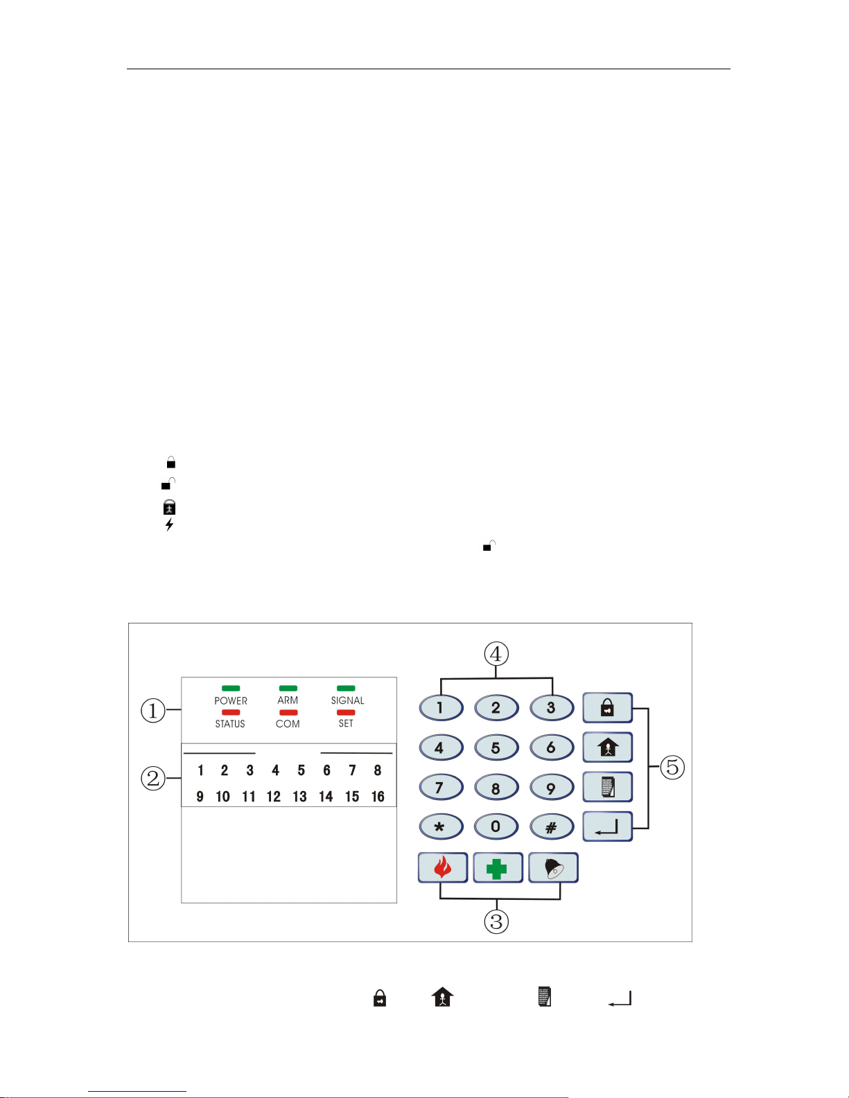
--------------------------------------------------------------------------------------------------------------------------------------------------------
PAGE 9OF 19
3.4 ARM
ARM means the system is in arm status and ready to response the alarm signal by detectors.
If arm successful, the buzzer give a long sound “di”, the light in corresponding zone is on for 1
second, and the “ARM” indicator light is on; If arm failed, the buzzer will give short sound “di” 3
times and “ARM” indicator light is off, and user should check if any zone is triggered or in
open-circuit condition, or the system is already in “ARM” status; If there is “ARM Delay”, the system
will exit the delay time after “ARM”, and it will give a short sound “di” per second till delay time is
over. The system will not alarm if any zone is triggered before the delay time is over.
3.4.1 Set Away ARM: All zones (except BY-PASS or Screened Zones) start “ARM” Status, if any
zone activated, the system will take relevant reaction, dial the alarm center, preset telephone
number or local police.
Operation: Press shortcut key on keypad or press “ ” on remote controller to setARM.
3.4.2 Set BOUNDARY ARM, also named Home ARM, when start “BOUNDARYARM” status,
non-BOUNDARYARM will not activate alarm.
1, Operation: Press Shortcut Key on keypad or press on Remote Controller to set
“BoundaryARM”.(BoundaryArm see 4.9)
3.4.3 Set Single Zone ARM/ DIS-ARM: the specified zone start “ARM“status, the other zones will
not activated alarm.
Operation: Set single zoneARM: Zone Number(01~16)+Shortcut Key,
Set single zone DIS-ARM: Password(6 bit)+Zone Number(01~16)+Shortcut Key,
3.4.4 Set Fast ARM: system will ignore the “DelayArm” status to “ARM” the system directly.
Operating: press *+
3.4.5
Set Compelled ARM:
1, Start Set Mode (see 4.4)
2, Operation: 76+0/1+ (Confirm Key) (1 means Open, 0 means close, Factory setting is 0)
Note: Boundary ARM and Single Zone ARM can be set at the same time, or switch to “ARM”
directly during Alarming status.
3.5 Set Disarm
1, Operation: User Password (6 bit)+(Confirm Key) (Factory User Password: 123456), or
press “ ” key on Remote Controller
2, Disarm Succeed, the buzzer will give a long sound “di”, andARM Indicator Light off; if system
refuse the command, the Buzzer will give a short sound “di” 3 times, or system already in disarm
status.
3.6 Remote Control
When System is set as Remote Controllable (See 4.18), (Factory Setting: non-remote control),
use telephone or mobile phone to remote control the alarm system to ARM, Disarm, Siren sound,
Record or Monitor etc.
Ringing times when dial the preset phone: (Set in Step 4.19, Factory Setting is 8 times); after
connected, Input user password: after a long sound “Di”, Access Remote Control Status;
3.6.1 Remote ARM, Disarm