Sercel GRC SPS-1500P User manual

SPS-1500P / FIC-1500P
Operaon Manual


SPS1500P / FIC1500P DOC: 10040534 Rev AA
Operation Manual Page 3 of 13
NOTICE
This manual is intended for private information only, with the understanding that any other use
of the subject matter, in whole or in part, by reference or otherwise, shall be only with the prior
knowledge and approval of Sercel-GRC Corp, and with the further understanding that this
manual is for informational purposes only and that suggestions and recommendations contained
herein shall not be understood or construed as a guarantee or warranty of any method, product
or device.
Federal copyright law protects the publication. No part of this publication may be copied or
distributed, transmitted, transcribed, stored in a retrieval system, or translated into any human
or computer language, in any form or by any means, electronic, magnetic, manual or otherwise,
or disclosed to third parties without the express written permission of Sercel-GRC Corp.
Any questions concerning the content of this manual, equipment operation, field maintenance,
maintenance assistance and operation or maintenance training courses should be directed to:
MODEL: SPS1500P / FIC1500P
OPERATION MANUAL
Copyright © 2017-2018 by Sercel-GRC Corp
All rights reserved worldwide.
Sercel-GRC Corp.
6540 East Apache Street, Tulsa, Oklahoma 74115-3616 USA
P.O. Box 581570, Tulsa, Oklahoma 74158-1570 USA
Telephone: (1) 918-834-9600/ Fax: (1) 918-838-8846
Visit our web page at www.Sercel-GRC.com

SPS1500P / FIC1500P DOC: 10040534 Rev AA
Operation Manual Page 4 of 13
Table of Contents
1.0 Overview ...............................................................................................................5
2.0 Accessories ..........................................................................................................5
3.0 Interface Panel......................................................................................................6
3.1 Module Display .................................................................................................7
3.2 Power Switch....................................................................................................7
3.3 USB Port...........................................................................................................7
3.4 Gauge Output...................................................................................................7
3.5 RS 485..............................................................................................................7
3.6 Charge Port ......................................................................................................7
3.7 Fuse Holder......................................................................................................7
4.0 Connections..........................................................................................................8
4.1 Gauge Connection............................................................................................8
4.2 Charging...........................................................................................................9
4.3 SPS1500 and FIC1500 Module......................................................................10
5.0 Additional Information .......................................................................................10
6.0 Specifications.....................................................................................................11
7.0 Troubleshooting.................................................................................................12
** WARNINGS **
WARNING AND ADVISORY INFORMATION TRAINED QUALIFIED PERSONEL MUST
PERFORM CONNECTIONS. HIGH VOLTAGES CAN BE PRESENT WHEN CONNECTING
TO HIGH VOLTAGE WELL. DISCONNECT ALL CIRCUIT POWER FROM SOURCE
BEFORE CONNECTING. ALWAYS EXERCISE CAUTION AROUND ELECTRONIC
EQUIPMENT. TO REDUCE THE RISK OF ELECTRIC SHOCK. NEVER PERFORM
WIRING ON A “LIVE” ASSEMBLY WHERE VOLTAGES ARE PRESENT.
SPS1500P / FIC1500P DOC: 10040534 Rev AA
Operation Manual Page 5 of 13
1.0 Overview
The SPS1500P and FIC1500P are the latest edition to the GRC portable surface equipment
family. These portables provide reliable and easily serviceable operation. The products are
designed to be a robust addition to any tech service. The compact design and SLA battery
allow the portable to be taken anywhere.
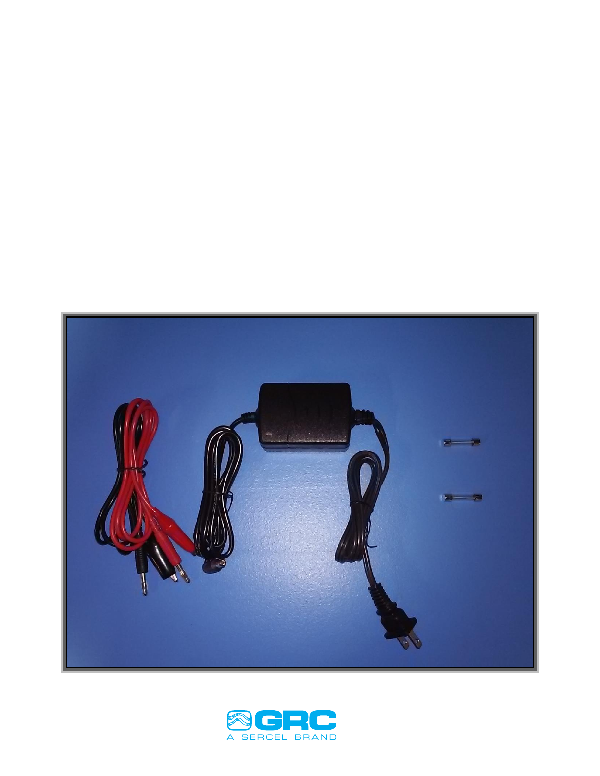
2.0 Accessories
Both the SPS1500P and the FIC1500P, come with a standard kit.
The kit includes:
Alligator Cables P/N 136-0104-01 and P/N 136-0103-01
Spare Fuses P/N 10039066
SLA Smart Charger P/N 10039065
Figure 1

SPS1500P / FIC1500P DOC: 10040534 Rev AA
Operation Manual Page 6 of 13
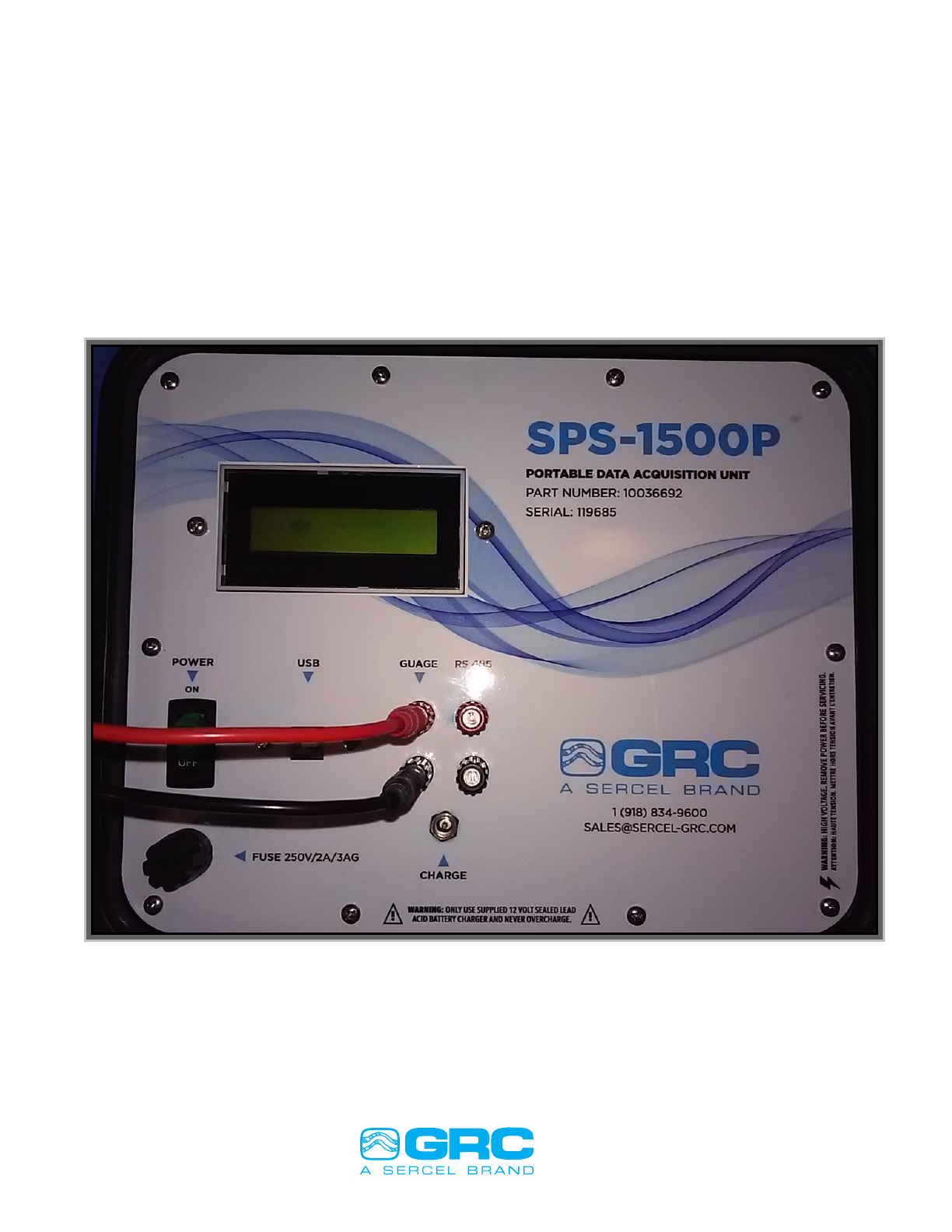
3.0 Interface Panel
The SPS1500P and FIC1500P Interface Panel.
Interfaces are:
1. Module Display
2. Power Switch
3. USB Port
4. Gauge Output
5. RS 485
6. Charger Port
7. Fuse Holder
Figure 2

SPS1500P / FIC1500P DOC: 10040534 Rev AA
Operation Manual Page 7 of 13
3.1 Module Display
The module display is the internal SPS1500 or FIC1500 gauge connection display. This
display provides visual indication regarding the connection and well parameters.
3.2 Power Switch
The power switch is the main power to the SPS1500P or FIC1500P. The power switch
allows the user to power the unit on when connecting to gauge, and off to conserve battery.
3.3 USB Port
The USB connection allows the SPS1500P or FIC1500P to be connected to a computer for
collecting or storing well data through serial communication.
3.4 Gauge Output
The gauge output is the direct line to the fused surface choke y-point or a direct connection
to a gauge for bench testing.
3.5 RS 485
The RS 485 output communication is a 2 wire A+ B- form of Modbus communication. This
communication allows the data to be served out to any requesting Modbus master device.
3.6 Charge Port
The charge port is a 5.5mm x 2.1mm barrel connection. This port provides a direct link from
the provided SLA smart charger to the battery.
3.7 Fuse Holder
The fuse holder is a standard press and twist holder for easy fuse replacement. Replace
only with same type fuse.
NOTE: See SPS-1500 and FIC-1500 manuals for more details.
SPS-1500 Manual Document Number: 006-0202-00
FIC-1500 Manual Document Number: 006-0199-00
SPS1500P / FIC1500P DOC: 10040534 Rev AA
Operation Manual Page 8 of 13
4.0 Connections
4.1 Gauge Connection
Connect the red and black wire to gauge device to be tested. The red wire “Signal” will
connect to the gauge or module signal input, and the Black wire “Ground” should connect to
the gauge housing or ground pin. When connecting to surface choke equipment the red
“Signal” wire should be connected to the signal input of any fuse protection equipment
connected to the surface Y-point.
Figure 3

SPS1500P / FIC1500P DOC: 10040534 Rev AA
Operation Manual Page 9 of 13
4.2 Charging
The charger port is a 5.5mm x 2.1mm barrel connection. The charger allows the SLA smart
battery charger to be connected at any time. The SLA smart charger provides the user with a
red/green indicator led for the indication of charge completion.
LED Indications:
Not Connected = Green
Charging = Red (Constant Current Charging 0.8 amp)
Charged = Flashing Green (Constant Voltage 14.5V)
Charge/Float charging = Green Dim (Float Charge Voltage 13.6V)
Reverse polarity = Red and Green Flashing (Reverse Polarity, Short Circuit)
Figure 4

SPS1500P / FIC1500P DOC: 10040534 Rev AA
Operation Manual Page 10 of 13
4.3 SPS1500 and FIC1500 Module
On power-up the SPS1500P or FIC1500P displays the firmware Version/Date Screen followed
by the devices Modbus address.
The SPS1500P will then cycle through the analyzing steps to acquire the tool, which takes 2-4
minutes. Once the tool is acquired, the LCD automatically scrolls through both gauge readings
and diagnostic screens. The display is updated once per second, and the screen advances
every 3 seconds by default. The displayed data includes the gauge serial number, the latest
sensor reading, and Modbus register address where that data can be polled.
The screens operate in a circular loop displaying tool parameters, then diagnostic screens, and
back to tool parameters. All enabled parameters on the tool will be displayed.
The FIC1500P surface controller is designed to read all Sercel GRC FSK gauges including
theQTIEG-4000 and the C4000/4500/5000/5500 line of gauges. The FIC1500P can read up to
six channels at the same time using FSK technology. Each gauge has a different number of
channels depending on the number of gauge sensors. A single channel can contain multiple
sensors. The FIC1500P has an LCD screen that displays data from each sensor.
5.0 Additional Information
Additional Instructions regarding the internal SPS1500 and FIC1500 module refer to the
following manuals.
SPS-1500 Manual Document Number: 006-0202-00
FIC-1500 Manual Document Number: 006-0199-00

SPS1500P / FIC1500P DOC: 10040534 Rev AA
Operation Manual Page 11 of 13
6.0 Specifications
Certifications: CE Compliance Tested
Approved for transport by air. DOT, IATA, FAA, and CAB certified
Display: 16x2 Backlit LCD
Polling Interface: RS-485/RS422 Isolated Modbus
PC Interface: Isolated USB COM Port for Modbus/Firmware Update
Supported Baud Rates: 1200, 2400, 4800, 9600 (default), and 19200 bps
Modbus ID 1 (default)
Internal Gauge Module Fuse: 100mA, GRC P/N 043-0047-00
7.0AH Valve regulated, spill proof Absorbent Glass Mat(AGM) technology
Gauge Power Out: 40 to 80 VDC Out (~80mA Current Limited)
Water resistant case, NK-7™ resin, ATA 300 | ASTM D4169 | Mil-std-810f | IP67
Operating Temperature -10°C~+40°C
Storage Temperature -40°C ~+70°C
Input Voltage AC 100 –264VAC (50 –60Hz)

SPS1500P / FIC1500P DOC: 10040534 Rev AA
Operation Manual Page 12 of 13
7.0 Troubleshooting
The SPS1500P or FIC1500P may experience communication problems due to noisy
environments, grounding problems, or installation issues. The LCD on the SPS1500P or
FIC1500P will display error codes depending on the failure it is detecting. Below is a list of
common error codes and possible solutions to assist with troubleshooting the SPS1500P or
FIC1500P.
DC-DC Bad
Possible Reason(s)
Bad ground connection
Bad SPS circuit board
Correction
Check Downhole readings (P-P & P-Gnd (Reverse Polarity Megger))
Change out SPS Circuit board
Baud Fast
Possible Reason(s)
Set voltage to high
Indicators
Continuous Baud fast error
Correction
Disable Auto Baud
Raise Max Tool Baud to 8-10
Adjust Set voltage (Approx. 60+/-)
Reboot or cycle power to restart analyzing stage
Disable Auto volt/ Auto Analyze
Note: During normal start-up communications with the tool you will see error
messages such as “High Amp”, “Low Amp”, “DC to DC Bad”, “Analyze 1”
through “Analyze 16” as well as other normal messages that are all part of
acquiring the tool. After the SPS1500P or FIC1500P analyzes the line current
from the tool you will see the message “SPS Power OFF” a couple of times and
then it will go through 2 or 3 phase Sync packages and then begin to get
header data. This is all part of normal operations of the S SPS1500P or
FIC1500P. There is only a concern when an error message is repeated multiple
times and communications is not established with the gauge after several
minutes.

SPS1500P / FIC1500P DOC: 10040534 Rev AA
Operation Manual Page 13 of 13
Low Amps
Possible Reason(s)
Cannot get voltage signal to tool
Disconnected from tool
Blown Signal fuse
Low amp setting set to high
Indicators
Continuous Low amp error
SyncPhs keeps restarting
Correction
Check Downhole readings (P-P & P-Gnd (Reverse Polarity Megger))
Check all connection(s)
Check Signal fuse
Check Setting of Low amp
Check Setting of High amp
High Amps
Possible Reason(s)
High and Low amp parameters have been corrupted
Bad ground
Bad SPS circuit board
Indicators
Continuous High amp error
Correction
Check Setting of Low amp (18-19 normally for SPS-1500 and 2-8 normally for
SPS-1501)
Check Setting of High amp (31-32 normally for SPS-1500 and 22 to 26 normally
for SPS-1501)
Check Downhole readings (Phase to Phase, Phase-Ground (Reverse Polarity
Megger))
Change out SPS-1500/SPS-1501

SPS1500P / FIC1500P DOC: 10040534 Rev AA
Operation Manual Page 14 of 13
Analyzing
Possible Reason(s)
Cannot get voltage signal to tool
Disconnected from tool
Blown Signal fuse
Indicators
Continuous Analyzing / SyncPhs
Correction
Check Downhole readings (Phase to Phase & Phase-Ground (Reverse Polarity
Megger)
Check all connection(s)
Check Signal fuse
Adjust Set voltage (Approx. 60+/- for 1500 and Approx. 40+/- for the SPS-1501)
No Modbus communication
Possible Reason(s)
Send / Receive connections reversed
Improper address
Not receiving Modbus request (Red LED by Modbus connector flashes when
SPS receives Modbus request)
Correction
Check for proper Modbus address
Swap Send / Receive wires on Modbus circuit board
Note: Many problems with the SPS1500P or FIC1500P can be solved with proper
grounding techniques. A good ground must be established from the production
tubing at wellhead back to the ground point at the surface package for proper
operation. This does not apply to the FIC1500P as it grounds to the TEC line.

Sercel-GRC Corp. is a worldwide leader in downhole data
acquision and the leader in proprietary technology for
measuring, recording and delivering reliable and accurate
well data with extremely high resoluons.
Sercel-GRC provides gauges and surface readout tools
for permanent, memory, mechanical and arficial li
appliapplicaons and is the manufacturer of the Amerada®
mechanical gauge used for over 80 years in the oil and
gas industry.
For more informaon on this product or any of the quality
monitoring and data acqusion soluons Sercel-GRC
offers, contact us.
Sercel-GRC Corp.
6540 East Apache
Tulsa, OK 74115-1570 USA
Telephone: +1.918.834.9600
Fax: +1.918.838.8846
Email: sales@Sercel-GRC.com
wwwww.Sercel-GRC.com
Anywhere. Anyme. Everyme.
This manual suits for next models
1
Table of contents


