Semtronics SmartLog X3 62580 User manual

TB-6123 Revision 10/06
Page 1 of 12
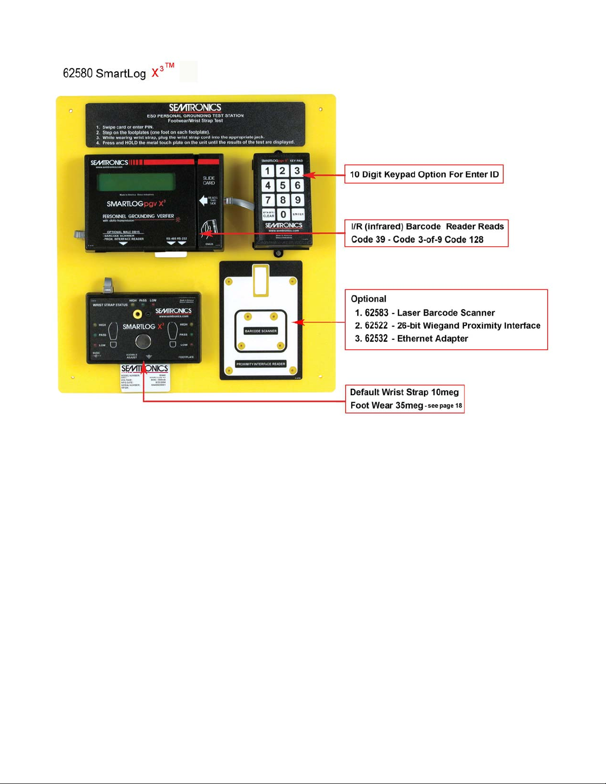
62580 SmartLogX3™
Wrist Strap and Footwear Tester
Automated ESD Record Keeping
Personal Grounding Verifier with Data Transmission
Hardware & Software Setup Instructions
For sales and Service in
North America contact:
ESD Systems.com
www.esdsystems.com
Phone: 508-485-7390
Fax: 508-480-0257
Corporate Office:
3651 Walnut Avenue,
Chino, CA 91710
Phone: (909) 627-8178
Fax (909) 627-7449
For sales and service in Europe and Asia
contact:
OK International - European Headquarters
Eagle Close, Chandlers Ford,
Hampshire, SO53 4NF U.K. England
http://www.okintl.com/locations
Tel: +44 (0)23 8048 9100
Fax: +44 (0)23 8048 9109
TB-6123 Revision 10/06
Page 2 of 12
Carefully unpack the Semtronics 62580 SmartLogX3™ wrist strap and footwear tester.
62580 SmartLogX3™ comes factory default and ready to install without any changes to clock’s
configuration. If a second SmartlogX3™ is being added or is going to be “Daisy-Chained”, refer to
next set of instructions for configuring clocks on a daisy-chain.
Note: Unit is not designed to work in high humidity environments where RH% is above 65 RH%.
Unpack and verify the following are included:
-1 SmartlogX3™ on yellow mounting plate with tester and keypad
-1 Dual foot plate
-1 Stereo cable for dual foot plate
-1 SmartlogX3™ 6.03 software
-1 AC adapter 12VDC 500mA center pos.
-1 DB9 serial adapter
-1 25” straight data cable
-4 mounting anchors
-4 mounting screws

TB-6123 Revision 10/06
Page 3 of 12
1. Configuration of Clocks Setting, Mounting and Cable Connection
Figure 1. Back Side of SmartlogX3™
A. Clocks Baud Rate, ID, Parity, Daylight Option and Port expand
Referring to Figure 1.
1. Plug the 120 volt AC power supply into the unit and then to the appropriate AC source.
Refer to Figure 1. to locate power input jack. The SmartLogX3™ will cycle through a self
diagnostic program. The time and date will appear on the screen when the diagnostics is
completed. Step 2 should not be performed until this is completed.
NOTE: If any of the below settings are not correct, press the Advance button
until the correct value appears on the display.
2. From the end of the self diagnosis, press the Menu button six times only (you’re giving a
20 sec limit to do so, or clock will need to be reset by disconnecting power adapter to re-
enter set-up menu). Refer to Figure 1 for Button locations.
3. Baud Rate should be set at 9600 (factory default). Press Enter for the next screen.
4. Parity should be set for ODD (factory default). Press Enter for next screen.
5. The SmartLogX3™ ID is a 2 digit field with valid I.D. number 00 through 63. Each
SmartLogX3™ should have a different I.D.# if on the same communication line. The
SmartLogX3™ should be numbered sequentially starting with 00, so that automatic
polling in the software will not be interrupted.
6. The Daylight Option is to enable daylight savings in the clock.

TB-6123 Revision 10/06
Page 4 of 12
7. Port expand should be set to yes (factory default).
8. Press Enter button once more to cycle to next setting before hitting Menu button to exit.
Note: Setting will not change if you don’t cycle to the next setting (by hitting the Enter
button).
B. Terminator Jumper, RS-485 Switch, RS-232 Switch and Relay Terminal
1. Terminator Jumper needs to be jumper only if clocks are in a daisy-chain. Jumper the
first SmartlogX3™ and the last SmartlogX3™ on the daisy-chain only. Stand alone
SmartlogX3™ does not need to be jumper.
2. RS-485 comes default on SLAVE position (right side) and does not need to be switched
unless unit is on a daisy-chain. For units on a daisy-chain set RS-485 to MASTER (left
position) for the first SmartlogX3™ (master clock) only.
3. Relay Terminal, The relay connections can be made on the back of the SmartLogX3™
(refer to figure 1) and can be used to control doors, gates, etc. The relay can hold a max
of 5A 250VAC/30VDC and 10A125VAC.
B. Cable Connections
Refer to Figure 2
1. IMPORTANT PC to First SmartlogX3™ Data Connection: Be sure to use the cable
provided inside box with unit. Connect the cable from the right port (RS-232) of the
SmartlogX3™ to the DB9 serial adapter connected to an open serial port on the PC
used. Cable is non-inverted and flat type when laid across table top if user desires to
make his/her own cable. Make sure cable is no longer than 50ft from the PC to the first
SmartlogX3™.
2. SmartlogX3™ to SmartlogX3™ Data Connection: These cables are different from the
cable supplied in the box with the SmartlogX3™. These cables are inverted and are the
same type of cables used in wiring of home telephones. Connect these cable to the left
port (RS-485) of first Smartlog™ to the left port (RS-485) of the second SmartlogX3™
only.
Note: No other clocks except the first clock (master clock) will use the right port (RS-
232), all other will connect through the left port (RS-485) in parallel, a RJ11 splitter will
be needed for daisy-chaining more than two units.
C. Mounting the SmartLogX3™And Scanner (Optional)
1. Mount SmartlogX3™at convenient location, makes sure to mount the SmartLogX3™ at a
height above the floor where all operators can see the display of the SmartlogpX3™ and
perform the necessary tests. Mount the barcode scanner to where all users are able to
reach the scanner. Use the anchor and screws provided with the SmartlogX3™.

TB-6123 Revision 10/06
Page 5 of 12
Figure 2. Data Cable Connections and Clock Settings
2. SmartlogX3™ Hardware
A. 10 Digit Key pad can be use to manually punch in ID badge number if no card is present.
Press CLEAR, enter ID number and press ENTER to start test.
B. Tester. Wrist strap test range is 1Meg to 10Meg Ohms. Footwear test range is 1Meg Ohms to
35Meg Ohms standard. SmartlogX3™ would have to be sent in to factory if test ranges is need
to be set differently. Tester test voltage is 12.0 VDC @ 0.40mA max for wrist strap and
footwear.
C. I/R Barcode Reader reads the barcode from the right hand side.

TB-6123 Revision 10/06
Page 6 of 12
TECHNICAL SUPPORT:
USA
Semtronics
3651 Walnut Avenue
Chino, CA 91710
Tel: (909) 627-8178
Fax: (909) 627-7449
NOTE: Unauthorized servicing or modifications to your monitor will void the product warranty and
may create dangerous conditions. Servicing should be performed only at the factory, or by a
Semtronics approved technician.
LIMITED WARRANTY
Semtronics expressly warrants that for a period of one (1) year from the date of purchase,
Semtronics 62580 will be free of defects in material (parts) and workmanship (labor). Within the
warranty period, a unit will be tested, repaired, or replaced at our option, free of charge. Call
Customer Service at 909-627-8178 (Chino, CA) or 781-821-8370 (Canton, MA) for Return Material
Authorization (RMA) and proper shipping instructions and address. Include a copy of your original
packing slip, invoice, or other proof of date of purchase. Any unit under warranty should be
shipped prepaid to the Semtronics factory. Warranty replacements will take approximately two
weeks.
If your unit is out of warranty, Semtronics will quote repair charges necessary to bring your unit up
to factory standards. Call Customer Service at 909-627-8178 for proper shipping instructions and
address. Ship your unit freight prepaid.
WARRANTY EXCLUSIONS
THE FOREGOING EXPRESS WARRANTY IS MADE IN LIEU OF ALL OTHER PRODUCT
WARRANTIES, EXPRESSED AND IMPLIED, INCLUDING MERCHANTABILITY AND FITNESS
FOR A PARTICULAR PURPOSE WHICH ARE SPECIFICALLY DISCLAIMED. The express
warranty will not apply to defects or damage due to accidents, neglect, misuse, alterations,
operator error, or failure to properly maintain, clean or repair products.
LIMIT OF LIABILITY
In no event will Semtronics or any seller be responsible or liable for any injury, loss or damage,
direct or consequential, arising out of the use of or the inability to use the product. Before using,
users shall determine the suitability of the product for their intended use, and users assume all risk
and liability whatsoever in connection therewith.

TB-6123 Revision 10/06
Page 7 of 12
62100/62102
DUAL INDEPENDENT FOOTWEAR AND WRIST STRAP TESTER
Installation and Operating Instructions
The Semtronics Dual Independent Footwear and Wrist Strap Tester is designed to test personal
grounding devices, wrist strap and ESD footwear, to satisfy the requirements and the
recommendations of the ESD Association.
Per ANSI/ESD S20.20 Paragraph 6.2.2.2 Personnel Grounding Guidance “A log should be
maintained which verifies that personnel have tested their personal grounding devices. (Wrist
Straps and ESD Footwear)”
Per ESD- S1.1 paragraph 6.1.3 Frequency of Functional Testing “The wrist strap system should be
tested daily to ensure proper electrical value.”
Per ESD Handbook TR 20.20 paragraph 5.3.2.4.2 Additional User Wrist Strap Testing “Proper
testing of the wrist strap includes the resistance of the groundable point on the end of the cord, the
cord itself, the resistor, the cord-to cuff snap connector, the resistance of the interface of the cuff,
the cuff/wrist interface, and the resistance of the person between the wrist and the hand that
contacts the test electrode.”
Per ESD Handbook TR 20.20 paragraph 5.3.2.2.2 Wrist Strap Ground Cord “At first glance, the
ground cord appears to be a relatively simple assembly. However, the design requirements are
considerable, given the wide range of user applications and the durability requirements of constant
tugging, flexing, and dragging over the edge of workstation tops and equipment chassis.”
Per ESD SP9.2 Appendix B – Foot Grounder Usage Guidance
“Compliance verification should be performed prior to each use ( daily, shift change, etc.). The accumulation
of insulative materials may increase the foot grounder system resistance. If foot grounders are worn outside

TB-6123 Revision 10/06
Page 8 of 12
the ESD protected area, testing for functionality before reentry to the ESD protected area should be
considered.”
The test resistance limits for footwear and wrist strap tests are controlled by the DIP
switches inside the tester. For a configuration different than the default settings, remove the
unit from the sign, remove the back of the case, and reset the DIP switches inside the unit
as desired.
Footwear resistance range selection.
DIP switches 1 & 2 control the “HIGH” limit for the footwear test selection as follows:
Switch 1 Switch 2 High Limit Resistance
ON ON 10 Megohms (1 X 10⁷)
OFF OFF 35 Megohms (3.5 X 10⁷)DEFAULT SETTING
ON OFF 100 Megohms (1 X 10⁸)
OFF ON 1 Gigohm (1 x 10⁹)
*At 1 Gigohms high limit resistance, a dirty footplate could result in a false pass. When using this setting,
special care must be taken to keep the footplate clean.
DIP switches 3 & 4 control the “LOW” limit for the footwear test selection as follows:
Switch 3 Switch 4 Low Limit Resistance
ON OFF 100 Kilohms (1 X 10⁵)
OFF ON 1 Megohms (1 X 10⁶) DEFAULT SETTING
OFF OFF 10 Kilohms
The “Optional” settings allow the use of custom resistance values when installed.
Wrist strap test option selection.
DIP switch 5 must be “ON” (DEFAULT SETTING) for the wrist strap test to be active. If the
wrist strap test is disabled by DIP switch 5 being “OFF”, the 3 LEDs for this test will remain “OFF”
at all times.
The “LOW” limit for the wrist strap test is set to 1 Meghms and can not be changed by the user.
DIP switch 6 in the “ON” position (DEFAULT SETTING - USA) sets the “HIGH” limit for the
wrist strap test to 10 Megohms (107). DIP switch 6 in the “OFF” position (DEFAULT
SETTING – EUROPE) sets the “HIGH” limit for the wrist strap test to 35 Megohms (3.5 X
107).
TB-6123 Revision 10/06
Page 9 of 12
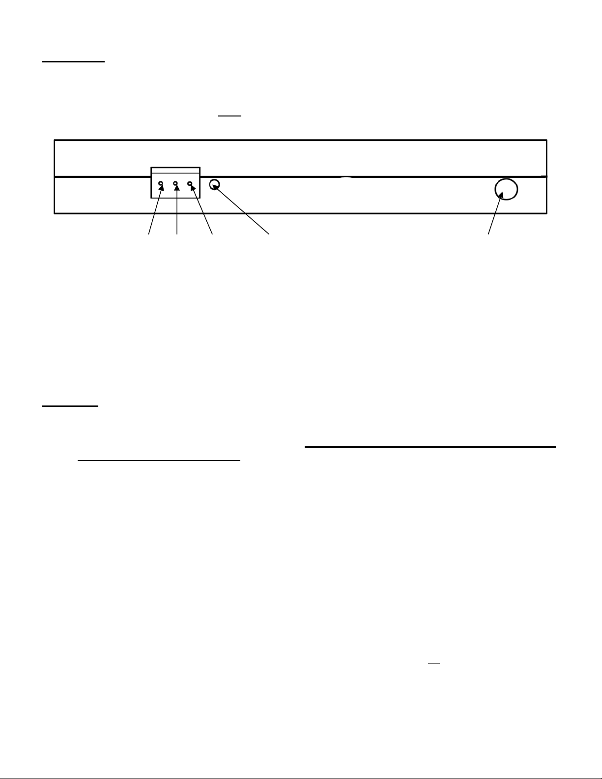
Installation
Insert one stereo plug of the 62103 Stereo Plug to Stereo Plug into the stereo jack on the bottom
of the tester. (See Figure 1.) Insert the other end of the stereo plug into the stereo jack at the
back of the foot plate. Verify that both plugs are fully inserted and tight.
Pin 1 Pin 2 Pin 3 Alarm Adjustment Connect stereo wire to footplate
1 & 2: closed/on standby
2 & 3: opened/on standby
2 = com
A relay with both “normally open” and “normally closed” contacts is included for your
convenience. The terminal block on the bottom of the tester has terminals for “normally
closed,” “common,” and “normally open” going from left to right. (See Figure 1.)
Operation
Pushing the touch plate on the front panel starts the test. During the test all LEDs will be
“OFF” to indicate that a test is in progress. The touch plate must remain depressed until
the test results are displayed. Depending on the configuration of the tester, the test could
require up to three (3) seconds.
The resistance is checked from the touch plate to the corresponding foot plate for each foot
and from the touch plate to the wrist strap connector jacks through the operator. A wrist
strap must be plugged into the appropriate jack before the touch plate is depressed if the
wrist strap option is activated. (See “wrist strap option selection” on page 2 above.)
The 62100/62102 can test both single and dual wrist straps. Single wrist straps are plugged
into the banana jack on the left side of the tester. (See Figure 2.) Dual wrist straps are
plugged into the phono jack on the left side of the tester. (See Figure 2.) The phono jack
(dual wrist strap) is above the banana jack (single wrist strap). Automatically determines
what type of wrist strap is being tested.
The LEDs will turn off while the test is in progress; the test results for each foot and wrist
strap will then be displayed for approximately three (3) seconds. If all test results are
“SAFE” the internal relay will be activated while the test results are displayed. The relay can
be used for opening an electric lock to an ESD sensitive area. The maximum contact rating
is: 1A@30VDC. 0.3A 110VAC, 0.5A 125VAC.

TB-6123 Revision 10/06
Page 10 of 12
If any of the test results are failed “HIGH” or “LOW” an audible alarm will sound. The LED(s)
indicating the failed test will be displayed for approximately three (3) seconds, and the internal
relay will not activate.
CALIBRATION AND PERIODIC TESTING:
The accuracy is specified as:
1. +5% for 1 Megohms and lower resistance ranges.
2. +10% for 1 Megohms and higher resistance ranges.
Does not require calibration and cannot be calibrated.
A periodic check (once every 6 to 12 months) using a precision resistance box should be
performed to verify proper operation.
A limit comparator, the 62080, can be purchased for the convenient periodic.
The 62080 contains 14 standard resistors to check the following high and low limit ranges:
1. 10K low
2. 10K safe
3. 100K low
4. 100K safe
5. 1M low
6. 1M safe
7. 10M safe
8. 10M high
9. 35M safe
10.35M high
11.100M safe
12.100M high
13.1G safe
14.1G high
TESTING PROCEDURE:
Wrist strap operation test.
1. Insert the 62080/62100/62102 test plug into the dual wrist strap connector on the
62100/62102.
2. Select the “1M low” range on the rotary switch of the 62080/62100/62102.
3. Press and hold the touch plate of the 62100/62102 until the test is completed. The results of
the test should be “fail low” for the wrist strap.
4. Select the “1M high” range on the rotary switch of the 62080/62100/62102 and repeat the
test. The results of the test should be “pass” for the wrist strap.

TB-6123 Revision 10/06
Page 11 of 12
5. Select the “10M safe” or “35M safe” setting, whichever one is appropriate, on the
62080/62100/62102 and repeat the test. The results of the test should be “pass” for the
wrist strap.
6. Select the “10M high” or “35M high” setting, whichever one is appropriate, on the
62080/62100/62102 and repeat the test. The results of the test should be “fail high” for the
wrist strap.
Footwear operation test.
1. Insert the 62080/62100/62102 test plug into the foot plate cable connector on the
62100/62102.
2. Select the appropriate “fail low” range on the rotary switch of the 62080/62100/62102.
3. Press and hold the touch plate of the 62100/62102 until the test is completed. The results of
the test should be “fail low” on both feet.
4. Select the appropriate “safe low” setting on the 62080/62100/62102 and repeat the test. The
results of the test should be “pass” on both feet.
5. Select the appropriate “safe high” setting on the 62080/62100/62102 and repeat the test.
The results of the test should be “pass” on both feet.
6. Select the appropriate “fail high” setting on the 62080/62100/62102 and repeat the test. The
results of the test should be “fail high” on both feet.

TB-6123 Revision 10/06
Page 12 of 12
TECHNICAL SUPPORT:
USA Europe
Semtronics Charleswater
3651 Walnut Avenue Unit 17, Millbrook Business Park, Sybron Way
Chino, CA 91710 Crowborough, East Sussex, TN6 3JZ, U.K.
Tel: (909) 627-8178 Tel: 01892 665313
Fax: (909) 627-7449 Fax: 01892 668838
LIMITED WARRANTY
Semtronics expressly warrants that for a period of one (1) year from the date of purchase, Semtronics
62100/62102 will be free of defects in material (parts) and workmanship (labor). Within the warranty
period, a unit will be tested, repaired, or replaced at our option, free of charge. Call Customer Service at
909-627-8178 (Chino, CA) or 01892 665313 (Crowborough, U.K.) for Return Material Authorization (RMA)
and proper shipping instructions and address. Include a copy of your original packing slip, invoice, or other
proof of date of purchase. Any unit under warranty should be shipped prepaid to the Semtronics factory.
Warranty replacements will take approximately two weeks.
If your unit is out of warranty, Semtronics will quote repair charges necessary to bring your unit up to
factory standards. Call Customer Service at 909-627-8178 for proper shipping instructions and address.
Ship your unit freight prepaid.
WARRANTY EXCLUSIONS
THE FOREGOING EXPRESS WARRANTY IS MADE IN LIEU OF ALL OTHER PRODUCT WARRANTIES,
EXPRESSED AND IMPLIED, INCLUDING MERCHANTABILITY AND FITNESS FOR A PARTICULAR
PURPOSE WHICH ARE SPECIFICALLY DISCLAIMED. The express warranty will not apply to defects or
damage due to accidents, neglect, misuse, alterations, operator error, or failure to properly maintain, clean
or repair products.
LIMIT OF LIABILITY
In no event will Semtronics or any seller be responsible or liable for any injury, loss or damage, direct or
consequential, arising out of the use of or the inability to use the product. Before using, users shall
determine the suitability of the product for their intended use, and users assume all risk and liability
whatsoever in connection therewith.
Table of contents


