Serveredge SED-KLHDMI-0819 User manual

1
USER’S MANUAL
Serveredge 8 and 16 port HDMI LCD KVM switch series USER MANUAL
PART NUMBER:
SED-KLHDMI-0819, SEDKLHDMI-1619

2
STATEMENT
UNITED STATES FEDERAL COMMUNICATIONS COMMISSION INTERFERENCE STATEMENT
This product has been tested and found to comply with FCC regulations Class B (Class B) digital device and FCC specifications
Details of Section 15.These specifications are intended to be used in a commercial environment without harmful interference
and to provide for the protection of regulated equipment. This equipment generates, and can radiate radio, so if you do not have
to install and use as specified in this manual, may cause interference to radio communications. However, there is no guarantee
that interference will not occur in a particular installation. If the equipment is turned on or o causing interference to radio and
television reception, the user should try the following to reduce the interference.
• Change the direction and move the receiving antenna.
• Increase the distance between the equipment and the receiver.
• Connect the device to the circuit outlet (not the interface to which the receiver is connected).
• Consult the dealer and an experienced radio / TV technician for help.
FCC WARNING:
change and modify non-qualified party which is responsible for the equipment is
made to void the user’s authority to operate the equipment.
CE WARNING:
This product is a Class B product. In a domestic environment, this product may
cause radio interference, and the user may need to take appropriate precautions.
ROHS:
This product is RoHS compliant.

3
model Configuration instructions
KLHDMI-0819 8input(USB+HDMI)1output+19inch LCD
KLHDMI-1619 16input(USB+HDMI)1output+19inch LCD
USER PRECAUTIONS
The manufacturer has the right to modify and alter the information, documentation and specifications contained in this manual
without prior notice. Manufactures makes no warranty, express, implied or statutory, disclaims or specifically disclaims it’s
possibility of sale and applicability for a particular purpose. The same applies to any sold and authorized manufacturer’s
software described in this manual. If the Software Program is found to be defective after purchase, the purchaser (and any
non-manufacturer, its distributor or its purchaser) will be responsible for all necessary service, repair and any incidental
or consequential damages resulting from the Software defect. The manufacturer is not responsible for any unauthorized
interference
with the radio or television caused by this equipment. The user must correct the interference personally. The manufacturer will
not be liable for any damage resulting from incorrect selection of the operating voltage before operation.
Please be sure that the voltage has been set correctly before use.
A typical LCD (liquid crystal display) has millions of pixels. A dead pixel is a defective pixel that does not display the correct
color. On the screen, it usually looks like a tiny black or white dot, which can also be any other color. In the manufacturing
process, even if a pixel on the tiny dust particles, or in the course of a slight impact during transport, may have a dead pixel. In
the ISO 13406-2 specification, four categories of acceptable screen dead pixels are defined: the first is the best product, and the
fourth is the worst. Almost all manufacturers use
the second level as a guarantee of the product, allowing a certain number of dead pixels exist, such as more than the tolerance
will change the screen. Since the manufacturer is of the opinion that this screen is permitted by the ISO specification, we are
not responsible for the replacement or warranty of the TFT LCD panel.
PRODUCT MODEL DESCRIPTION PACKAGE CONTENTS
The multi-computer KVM switch package includes the
following:
• LCD KVM switch host x 1
• Power adapter x 1
• User Manual( CD) x 1
• rack fixing plate x 2
• screw package x 1
Check that all parts are present and that they are not damaged in transit. If you encounter problems, contact your
dealer.
To prevent damage to the machine or equipment connected to the machine, please read this manual carefully and
follow the instructions to install and operate it.
* There may be additional product features since the publication of this manual. Please visit our website to download
the latest version of the user’s manual.
Manual date: 2018-05-01

4
CONTENTS
About this manual ............................................................................................ 5
Common Terms ................................................................................................. 5
Chapter I
Introduction .......................................................................................................... 6
• Product description ...................................................................................... 6
• Product Features ........................................................................................... 6
• Hardware requirements ............................................................................. 7
- Console
- Computer
- Cable
- Operating system
• Component ........................................................................................................ 8
- Front view
- Rear view
Chapter II
Hardware installation .................................................................................... 10
• Stacking and installation
- Standard rack mounting (single rail series)
- Standard rack mounting (dual rail series)
- Assembly and disassembly of KVM modules
- Keyboard module removal
- Single device installation
Chapter III
Basic operation ................................................................................................. 16
• Hot swap ............................................................................................................ 16
- Hot plug computer connection port
- Hot swap control port
• Connection port selection ...................................................................... 16
- Manually switch selection
- OSD menu screen selection
- Hotkey selection
• Power o and restart .................................................................................. 17
Chapter IV
OSD Operation .................................................................................................. 18
• Introduction to OSD .................................................................................... 18
• OSD login .......................................................................................................... 18
• OSD hotkey ...................................................................................................... 18
• OSD main selection menu ..................................................................... 18
• OSD main menu title .................................................................................. 18
• OSD function key introduction ........................................................... 19
- F1 GOTO
- F2 SCAN
- F3 LIST
- F4 QV
- F5 EDIT
- F6 SET
Appendix
• Safety instructions ...................................................................................... 25
- General
- Rack mounting
• Product specification ................................................................................ 27
• Warranty conditions ................................................................................... 28

5
ABOUT THIS MANUAL
COMMON TERMS
PRODUCT INFORMATION
This User Manual will assist you in the eective use of product features, including the installation, setup, and operation of your
equipment. You can find out what is included in this manual from the following:
Chapter I Introduction – This chapter introduces the rack-based KVM device system, including its functions, features, and
benefits, and describes and describes its front and rear panel components.
Chapter II Installation – This section describes how to install the product, and the necessary steps -include a single base unit
is mounted,multi-switch stage connection mounting, mounting extension IP module.
Chapter III Basic Operation – Explains the basic operational concepts of the KVM switch.
Chapter IV OSD Operation – provides an introduction to the OSD (Screen Menu) of the complete KVM switch and explains
how to use it.
Appendix – Mainly provides specifications and other technical information about the relevant KVM switch.
Symbol indicates the text information that should be entered
[ ] The parentheses indicate the keys that need to be entered. For example, [Enter] means pressing the Enter key. For keys
that need to be entered at the same time, they are placed in the same parenthesis, and the keys are connected by a plus sign.
For example: [Ctrl+Alt]
1. The number indicates the actual number of operating steps.
Diamond symbol indicates that information is provided for reference, but is not related to the operation steps.
The origin symbol indicates the classification sub-item information, regardless of the operation steps.
To find out more about KVM’s products and how to use them more eiciently, please visit our website or contact an authorized
dealer for more contact information.

6
PRODUCT DESCRIPTION
PRODUCT FEATURES
INTRODUCTION
The 8/16-port USB Rack KVM Switch is a versatile device that allows administrators to access an 8/16 HDMI computer from a
set of USB keyboards, mice,or a set of PS2 keyboards, mice, and consoles.
Provides four easy ways embodiment, the installation can be switched computer architecture: (1) connecting the port select
buttons using a switch on the front panel; (2) a combination of the input from the keyboard hotkey; (3) from the screen display
(OSD) on the menu select. The Auto Scan feature provides automatic scanning and monitors the computers in the installation
architecture one by one. (4) Remote network control operation through the network port of the extended IP module to connect
to the computer above the KVM.
This product is very quick and easy to install. Simply connect the cable to the appropriate port, no software setup, no
complicated installation procedures, and no incompatibilities. Because the device can directly access the input data of the
keyboard, it can operate on a variety of operating platforms (compatible with PC, Mac, Sun, etc.).
Since it is allowed to manage the computer connected to it from a single console,the installation of a group of KVMs, (1) can
eliminate the expense of purchasing individual keyboards,monitors and mice for each computer; (2) saving the extra equipment
will occupy Space; (3) saving energy costs; (4) avoiding the inconvenience and waste of moving back and forth between
computers. (5)Rapidly upgrade to the remote network control mode of IP control mode.
• A set of USB console controls 8 units or 16 units HDMI computer interface
• The console supports USB TYPE A interface type keyboard and mouse device
• LCD type KVM maximum resolution is 1920×1080@60HZ
• Rack type KVM maximum resolution is 4K X 2K @60HZ
• Switch the computer through the front panel buttons,keyboard hotkeys and screen menu(OSD)
• The controlled device connected BIOS-level access,without fear of invasion risk of viruses and Trojans
• The controlled computer does not need to install any software and drivers, and the controlled computer directly
recognizes KVM.
• Scalable remote network control mode IP extension board
• Support OSD to set user login mode and increase KVM login security requirements
• Both local and remote IP modes support high video resolution support 480i, 480p, 720p, 1080i and 1080p(1920×1200),
4K X 2K Ultra HD resolution
• Support widescreen resolution
• Support DDC communication to adapt to dierent graphics devices
• Auto scan function monitors all computer operations
• Support for cross-platform operations- Windows, Linux, Mac*, and Sun*
• The computer mouse and mouse connection port is controlled by Keep Online technology to simulate the mouse and
keyboard.The device is safe and stable,and the switching is fast without delay.
CHAPTER I

7
CONSOLE
COMPUTER
CABLE
HARDWARE REQUIREMENTS
OPERATING SYSTEM
For more operating system support, please pay attention to the latest version of product compatibility.
• A set of HDMI display screens that are compatible with the highest resolution of any computer to be installed under the
installation architecture
• A set of USB interface mouse
• A set of USB interface keyboard
The following devices must be installed on each computer:
• A set of HDMI video display cards
• USB Type A port
KVM device provides two of Connectors cable used according to the user selection:
• the HDMI cable
• USB TYPE A to TYPE B cable
Note: The cable length aects the quality of the display. If you need other lengths of cable, contact the merchant you
purchased to purchase a cable suitable for this switch.
Operating system Version
Windows Windows
2000/ XP/ 2003/ 2008/ Vista/ 7/ 10
Linux Red Hat 9.0 or higher
SuSE 10/11.1 or higher
Debian 3.1/4.0
Ubuntu 7.0 4 /7.1 0
UNIX AIX 4.3 or higher
Free BSD 5.5 or higher
Sun Solaris 8 or higher
Mac OS 9.0 to 10.6 (Snow Leopard)
Novell Net ware 6.0 or higher

8
FRONT VIEW
COMPONENT
Numbering component Functional description
1 Port switch selection button
According to the serial number of the switching port, the user
can press the corresponding serial number button to switch
the corresponding port to the current operating port, and at the
same time, the internal buzzer of the device will be heard, and
the switching action is confirmed to be performed correctly. The
selected port inline LED will also illuminate.
2 In-line LED indicator
Each button has two LED indicators embedded inside it .
The user can judge the current working condition and usage of the
device according to the LED indicator embedded inside the button.
• Corresponding to the [ON] position is a red LED, indicating
the online indicator, which means that the port is connected
to the controlled computer device being used; if the [ON] LED
is not lit, it means that no computer is connected to the serial
number. The computer on the port or connected is already o.
• Corresponding to the green LED in the [Select] position,
indicating that the port indicator is selected, which means that
the computer with the currently selected serial number can
be operated. If the [Select] LED is not lit, it indicates that the
serial port is controlled. The computer is not selected, not the
computer currently operating.
3 Device reset button
In the small round hole marked with the [RESET] text, to reduce
the user’s misoperation caused by the device restart, the product
uses a built-in reset button, the user can use the needle-shaped
object to insert into the round hole for 1-3 seconds as needed.
Complete the reset operation of the KVM device.

9
REAR VIEW
Numbering component Functional description
1 KVM connection port
Connect one end of the HDM connector of the corresponding KVM cable
to the HDMI port of the computer and monitor, connect the TYPE B of
the USB to the corresponding port of the KVM, and connect the TAPE A
port of the other end to the USB port of the computer. (Please refer to the
description of the relevant section of “Cables” for the cable used.)
2 Local HDMI display port Connect the connection cable of the console hdmi display to this port.
3 USB keyboard, mouse port The keyboard and mouse device connected to the USB port of the
console, the interface is USB Type A.
4 Power jack Plug the power adapter's cable here.
5 External Video convertor interface The interface could output one way VGA signal, Which could be
connected with IP BOX
16-port KVM rear view
8-port KVM rear view
4-port KVM rear view
5 2
4 3 1

10
STACKING AND INSTALLATION
STANDARD RACK MOUNTINGSINGLE RAIL SERIES
HARDWARE INSTALLATION
1. Regarding the placement of LCD KVM important safety information switch has been listed in the Appendix in, please first
check the contents before operating.
2. Before installation, please make sure that all the devices you are connected to are powered o. You must unplug all the
computer power cords with keyboard power on function.
3. The package of the LCD KVM switch is stued with filler to protect the product during transportation. Please LCD module
in the subsidiary protective film and a filler, prior to filling out the installation.
The LCD the KVM switch can be placed on any suitable surface, and suicient safety support apparatus plus additional cable
weight amount ; Confirm plane is clean and free of debris may aect other switch ventilation and normal operation.
1. Screw the front flange to the rack first. Slide the bars with
the rear flange towards the rack until the flanges make
contact with the rack, then screw the rear flanges to the
rack.
2. Slide the switch onto the support flanges. Use the screws
supplied with this package to loosely attach the front of
the switch to the front of the rack.
3. Slide the rear attachment sliding brackets along the slide
bars until they contact the rear of the switch.
4. Use the screws supplied with this package to attach
the bars to the rear of the switch.At this point, you have
completed the rack mounting of the LCD KVM switch for
subsequent use.
CHAPTER II

11
STANDARD RACK MOUNTING DUAL RAIL SERIES
1. Screw the front flange to the rack first. Slide the bars with
the rear flange towards the rack until the flanges make
contact with the rack, then screw the rear flanges to the
rack.
2. Slide the LCD KVM device into the support flange, use
screw in this package provided with wire front portion of
this switch is fixed to the front of the rack and locked.
3. Slide the rear attachment slide bracket along the side
strips until it reaches the rear of the switch.
4. Use the screws supplied with this package to attach
the bars to the rear of the switch. At this point, you have
completed the rack mounting of the LCD KVM switch for
subsequent use.
Note: There may be dierences between the dual rail mounting bracket and the single rail
bracket. For the dual rail products you have purchased, please refer to the illustration below
for installation.

12
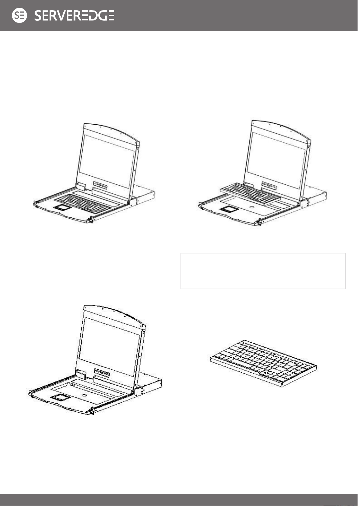
ASSEMBLY AND DISASSEMBLY OF KVM MODULES
The LCD panel and keyboard and mouse components of this series can be removed and separated from the KVM part of
the rear. This design allows you to change the KVM components as needed, or remove the KVM components after the KVM
components are damaged and return them to the manufacturer for repair and replace.
Please refer to the illustration for loading and unloading operations:
• Loading and unloading of single slide rail module:
For single-port HDMI KVM connection, please connect the interface adapter module as shown below.
1. Now put this series of products on the appropriate
operating platform, and prepare the screwdriver tool for
subsequent disassembly and assembly screws.
2. Remove the KVM assembly and the front LCD assembly
by removing the KVM assembly and the mounting
screws on the brackets on both sides as shown.
3. Disassembly and installation process Pay attention to the
interface between the KVM module and the LCD module.
Otherwise, the connection interface may be damaged
and the device function may be caused. Invalid.
4. Replace the KVM module at the rear of the LCD. Fix the
screws in the corresponding screw holes as shown in
the figure, and then fix the whole machine in the cabinet
according to the corresponding steps.

13
• Loading and unloading of dual slide rail modules:
1. Now put this series of products on the appropriate
operating platform, and prepare the screwdriver tool for
subsequent disassembly screws.
3. Replace the KVM module at the rear of the LCD. Fix the
screws in the corresponding screw holes as shown in
the figure, and then fix the whole machine in the cabinet
according to the corresponding steps.
2. Remove the KVM assembly and the front LCD assembly
by removing the KVM assembly and the mounting
screws on the brackets on both sides as shown.
14
KEYBOARD MODULE REMOVAL
If you need to replace the keyboard of the LCD module part or repair this part, you can also disassemble according to the
following figure.
1. Place the LCD KVM on the rack and fix it, and flip the LCD
panel to expose the operating surface of the keyboard and
mouse.
3. Pull the keyboard out of the limit slot, find the USB port
on the connection, and remove the USB Type A connector
from the interface.
The keyboard can be removed, and the removal of the
keyboard module is completed.
2. There is a circular hole at the bottom of the keyboard
panel. You can use your finger to pass the circular hole to
lift the keyboard up.
Note: If you replace the installation, please plug in
the USB interface of the keyboard first, then put the
keyboard module into the limit slot.

15
EXTENSIVE APPLICATION OF DEVICE
The device could extend a interface of video ouput, via special video cable to connect VGA Display monitor; or as a input
interface of IP BOX. Connection way as following;
Note: Please confirm the power failure status of the equipment before installation. To prevent equipment damage during
installation, please confirm that all installed equipment has good grounding protection.
Note: Make sure all plugs are connected to the KVM port jacks of the same group(all are connected to port1,or all are
connected to port2).
SINGLE DEVICE INSTALLATION
1. Plug your USB keyboard and mouse into the USB console port on the switch’s back panel.
2. The HDMI display video signal line is connected to the HDMI control terminal port and powered.
3. Using a set of KVM cables of the model corresponding to this product, plug the HDMI connector into the HDMI port of any
available HDMI port area of the switch.
4. Plug the HDMI video connector and USB plug corresponding to the KVM cable into the corresponding port on the
computer.
5. Plug the power adapter included with this package into the AC power source, and then plug the other end of the power
adapter into the power jack on the switch.
6. Turn on your computer.

16
HOT PLUG
CONNECTION PORT SELECTION
BASIC OPERATION
The KVM switch supports hot-plug, removing and removing components by unplugging the cables connected to the
computer’s port without shutting down the switch. To make the hot swap function work properly, follow these steps:
Hot – Plug Computer Connection
In order for OSD Menu to correspond to the KVM connection port changes, you must reset OSD Menu to display the latest
connection port information, OSD menu settings. Please refer to the OSD Menu section for more information about functions
and usage.
The KVM switch can be used to quickly switch to any computer connected to the KVM in three modes: manual key selection,
OSD Menu screen selection, and hotkey selection.
Switch the Selection Manually
Use the buttons on the front control panel to select a port.
OSD menu screen selection
See the relevant section of the OSD operation for more information.)
Hot – Plug Console Port
This product also provides keyboard, mouse and display hot-plug function. This product provides keyboard and mouse port
for two interface types. Users can select the corresponding device connection type according to their usage and carry out
corresponding control operation.
CHAPTER III
Note: If your computer’s operating system does not support hot-plug functionality, this feature may not function properly.
Note: If you access the USB and PS2 keyboard, mouse device, you do not have to use two types of devices, otherwise,
may cause the accused computer equipment mouse and keyboard response exception.

17
POWER OFF AND RESTART
If you need to power o the KVM switch, do the following before turning it back on: 1.Unplug the power supply to the KVM.
2.Turn o all computers connected to the KVM switch. 3.Wait about 10 seconds, then reconnect the KVM switch. 4.Turn on the
computer.
Hotkey selection
This product oers four hotkey switching methods :
[SCRLL] + [SCRLL] + [NUM]
[CTRL]+[CTRL]+[NUM]
[ALT]+[ALT]+[NUM]
[SHIFT] + [SHIFT] + [NUM]
The default hotkey switching combination key is [SCRLL]+[SCRLL]+[NUM] where [NUM] is the keyboard number 1-16,
and the keyboard combination hotkey is input to complete the carriage return completion command, and the KVM switch
will switch the corresponding number. Port computer. If you want to change the hotkey’s key combination, you can make
settings and changes in the corresponding options in the OSD menu. (See the relevant section of the OSD operation for more
information.)

18
OSD INTRODUCTION
OSD LOG IN
OSD HOTKEY
OSD OPERATION
OSD MAIN MENU
OSD (On Screen Display), provides a menu driven interface to handle the computer switching procedure to provide instant
access to any computer on the installation.
Active OSD, following picture will be shown on the screen:
The OSD function provides a two-level (administrator / user) password mechanism. The factory default setting is no need
to login password authentication, so you are the first time to open the OSD main menu, no need to enter the login password
to enter the OSD main menu screen for the corresponding operation. If you want to add this function, you can enter the
OSD menu, in [ F6 ] “SET” option to set the login password is set successfully, the subsequent login requires the correct
administrator / user password to enter the OSD menu Interface operation. When you enter the setting options, some functions
may need to be edited and modified by the administrator. The default administrator password is admin. You can also modify
and change them as needed.
By default, you can type the [CTRL] key twice to have the OSD menu appear on the screen of the controlled display and see
the connection information and status information about the connected computers on the KVM switch.
CHAPTER IV
Note: You can change the keyboard hotkey on the OSD menu according to your needs. This product provides 4 sets of
optional OSD menu hotkey combinations. You can select the operation according to your needs. (Please refer to the OSD
menu for detailed description. )
• [F1] [F2] [F3] [F4] [F5] [F6] at the bottom of the screen
is the function setting of OSD menu, and corresponding
operation and setting of corresponding function by
keyboard.
• After entering the OSD main screen, the port number in
the center of the screen is the port number of the selected
PC. To move up and down through the list one line at a
time, use the [↑] [↓] Arrow Keys, press [Enter] to select
the switch port.
• Please press [Esc] to exit the OSD menu interface
• To move up or down a row in the list, use the[↑] [↓]arrow
keys. If the number of rows in the list is larger than the
number that the screen can display, the screen scrolls.
• When the OSD menu is closed, a small blue window will
appear on the screen showing the port number that is
currently switched to.

19
OSD INTRODUCTION
F GOTO:
OSD functions are used to configure and control the OSD. For example, you can: rapidly switch to any port; scan selected ports
only; limit the list you wish to view; designate a port as a Quick View Port; create or edit a port name; or make OSD setting
adjustments.
To activate the OSD function key:
1. Press any function key [F1] [F2] [F3] [F4] [F5] [F6] at the bottom of main screen to input the function key.
2. On the sub-menu, move the selection column to the option, and then press the {Enter} key.
3. Press the [Esc] key to return to the previous menu.
Press the [F1] key to start the GOTO function. The GOTO
function allows you to switch directly to the connection port by
typing the port name or its port number.
1. To use “NAM” method, move highlight bar to “NAME”,
press [Enter], input name of a port, then press [Enter] to
confirm.
2. To use PN method, move highlight bar to “PN”, press
[Enter], input port number, then press [Enter] to switch.
If the port number is invalid, it will remind the user to input
again.
To return to main menu, press [Esc].
Note:
1. When keying name, if there is a matching name, the
matched name will appear on the screen, just press
[Enter] to switch to that port.
2. In the “PN” port input box, only allow the input of
numbers, such as the input of other characters
are regarded as invalid input, and can hear the
equipment issued by the warning tone.
Heading Explanation
PN
This column lists the port numbers for all the CPU ports on the
installation. The simplest method to access a particular computer is to
move the highlight bar to it, then press [Enter].
QV If a port has been selected for Quick View scanning, an arrowhead
symbol displays in this column to indicate so.
PC The computers that are powered on and are on line have an arrowhead
symbol in this column to indicate so.
NAME If a port has been given a name, its name appears in this column.

20
F SCAN
F LIST
F QV
Press the [F2] key to start the SCAN function. The SCAN function allows the KVM device to automatically switch the
connection port. You can set and view it according to the set time interval. To end the SCAN scan, press the [Space] button
to exit the scan mode. By default, the interval between two port scans is 5 seconds. (Refer to the description of [F6] function
settings for modification).
Press the [F3] key to start the LIST function. This function can display the port according to the mode that the user wants to
display. It is convenient for the user to quickly and selectively view the corresponding port according to the common habits. The
mode provided is as follows:
Press the [F4] key to set or cancel the QV on the port where the cursor is stuck. If the port has an icon, it means the port is set
to the express browsing mode. You can see the set port information in QVIEW mode, otherwise it is the normal port.
Choice Meaning
ALL Lists all of the ports on the installation.
QVIEW Lists only the ports that have been
selected as Quick View Ports.
POWERED ON Lists only the ports that have their
attached computers powered on.
POWERED ON
+ QVIEW
Lists only the ports that have their
attached computers powered on and
have been selected as Quick View Ports.
QVIEW + NAME
Lists only the ports that have been
selected as Quick View Ports and have
name.
NAME Lists only the ports that have names.
This manual suits for next models
1
Table of contents
Other Serveredge Switch manuals


