STI UB-2 User manual

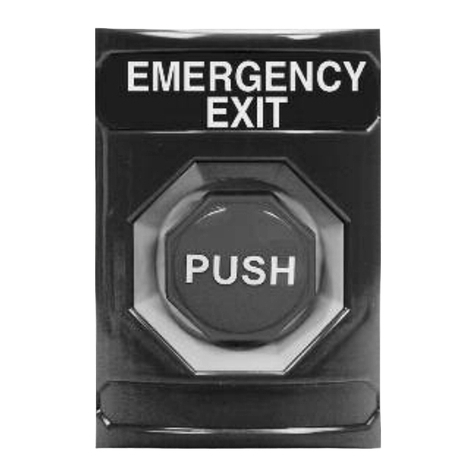
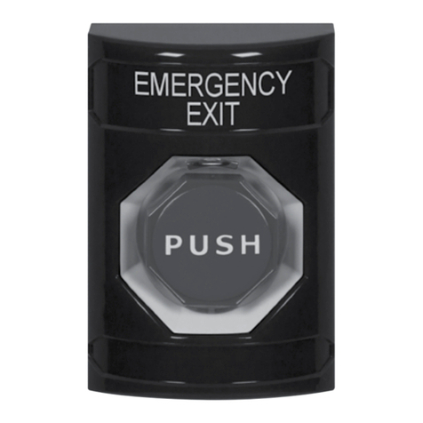
UB-2 2” Universal Button
UB-2/LTUL Universal Button with Latching Timer
We protect the things that protect you.®
ADA
Compliant
ADA
Compliant
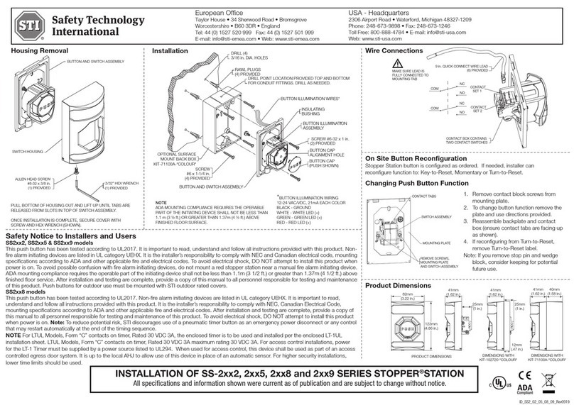
For UB-2/LTUL the enclosed timer is to be used and installed per the enclosed LT-1UL installation
sheet. For access control installations, power for the LT-1UL Timer must be supplied by a power
source listed to UL294. When used for access control, this device shall be used as part of an access
controlled egress door system. It is up to the local AHJ to allow use of this device in place of an
automatic sensor. For higher security installations, lower time limits should be used.
Pour les modèles UB-2/LTUL, la minuterie intégrée doit être installée et utilisée suivant la fiche
d’installation LT-1UL fournie. Pour les installations de contrôle d’accès, l’alimentation de la minuterie
LT-1 doit être fournie par une source homologuée UL294. Lorsque cet appareil est utilisé aux fins
de contrôle d’accès, il doit faire partie d’un système de porte de sortie à accès contrôlé. Il incombe
donc à l’AHJ local d’autoriser l’utilisation de cet appareil au lieu d’un capteur automatique. Pour les
installations de sécurité plus renforcée, des délais inférieurs doivent être utilisés.

NOTES
It is important to read, understand and follow all instructions provided with this product. It
is the installer’s responsibility to comply with NFPA 70 & 101, NEC, mounting specifications
according to ADA and other applicable electrical codes.This switch is rated Type NM (Non-
Monitored) for non-emergency signaling. Not to be used in place of panic hardware. To
avoid electrical shock, DO NOT attempt to install this product when power is on. ADA
mounting compliance requires the operable part of the initiating device shall not be less
than 3 1/2 ft. (1.1m ) or greater than 4 1/2 ft. (1.37m) above finished floor surface. After
installation and testing are complete, provide a copy of this manual to all personnel
responsible for testing and maintenance of this product.
REMARQUES
Il est important de lire, de comprendre et de suivre toutes les instructions fournies avec
ce produit. Il incombe à l’installateur de se conformer aux normes NFPA 70 et 101, NEC,
aux spécifications de montage selon l’ADA et aux autres codes de l’électricité en vigueur.
Pour les cotes de type SM (auto surveillée), le message d’Urgence peut être apposé sur le
modèle UB-1 lorsqu’il est utilisé dans un système intégrant un dispositif de déclenchement
compatible et homologué. Toutes les autres applications sont cotées de Type NM (non
surveillée) pour la signalisation non urgente. Pour éviter un choc électrique, NE tentez
PAS d’installer ce produit lorsqu’il est sous tension. La conformité aux règles d’installation
de l’ADA exige que la partie utilisable du dispositif de déclenchement soit installée à une
hauteur située entre 3 1/2 pi (1,1 m) et 4 1/2 pi (1,37 m) au-dessus du plancher fini.
Une fois l’installation et les essais terminés, vous devez fournir une copie de ce manuel à
l’ensemble du personnel chargé de l’essai et de l’entretien de ce produit.
SWITCH RATING
2 Independent Form “C” contacts Model UB -2/LTUL
UB-2 rated at: 10A, 1/2 HP, 125/250 VAC Form “C” contacts on timer rated:
6A, 30 VDC 30 VDC 3A, 1.0 pf
100,000 Operations
Temperature: -40° to 185°F (-40° to 85°C)
- 2 -
UL294 Performance Levels:
Line Security: I
Attack: I
Endurance: IV
Standby Power: I
1. TO CHANGE BUTTON COLOR AND ROUND MESSAGE
1. Choose button message and color. If same as existing, proceed to 2.
2. To remove push button actuator assembly, pinch together actuator tabs in
direction of arrows shown above and push through plate.
3. Push actuator through plate.
4. Align actuator cap to push button actuator. Align button slots to tabs on
push button actuator.
5. Snap button onto push button actuator and rotate right to lock.
6. Insert spring into push button actuator.
7. Pinch legs of push button actuator and align into die cast plate.
- 3 -
ALIGN TAB ON ACTUATOR WITH SLOT BUTTON.
TURN CLOCKWISE TO LOCK.
INSERT ASSEMBLY WITH SPRING INTO PLATE.
PLATE SPRING
ACTUATOR CAP
ACTUATOR
2 in. BUTTON
DIE CAST PLATE
SPRING
PUSH BUTTON ACTUATOR
ACTUATOR CAP
2 in. BUTTON
ALIGN TAB ON ACTUATOR
WITH SLOT BUTTON.
TURN CLOCKWISE TO LOCK.
INSERT ASSEMBLY WITH
SPRING INTO PLATE.
FRONT VIEW
PLATE SPRING
ACTUATOR CAP
ACTUATOR
2 in. BUTTON
DIE CAST PLATE
SPRING
PUSH BUTTON ACTUATOR
ACTUATOR CAP
2 in. BUTTON
3.22 in.
(82mm)
4.83 in.
(123mm) 2 in.
(51mm)
.9 in.
(24mm)
1.33 in.
(34mm)
12
34
SCREWDRIVER
UB-1L LED PCB
NYLON WASHER
SELF TAPPING SCREW
TO SUPERVISED STATION
OR AUXILLARY DEVICE
SW1
SW2
NC
COM
NO
NC
COM
NO
MAG LOCK
MESSAGE LENS PCB
12–24VDC
BUTTON LED
NORMAL POSITION BUTTON ACTIVATED
MAGNETIC LOCK
BUTTON LAMP
MESSAGE LAMP
ON
ON
OFF
OFF
OFF
ON
NO
NC
COM
LED –
LED +
SWITCH 1
SWITCH 2
TOP TAB
19085 #6 - 32 x 1” OVAL
HEAD MACHINE SCREW
(2) PROVIDED

- 4 -
2. CHANGE TOP MESSAGE
Refer to notes on page 2 for “EMERGENCY” message use.
1. Remove LED circuit board.
2. Remove current message by pushing in and down on tabs 1 and 2 with
a small screwdriver. If necessary, also push in and down on tabs 3 and 4.
Once message is loose, remove from the front of the plate.
3. Select new message and snap into place. Blank plates are included to
create your own custom message.
ALIGN TAB ON ACTUATOR WITH SLOT BUTTON.
TURN CLOCKWISE TO LOCK.
INSERT ASSEMBLY WITH SPRING INTO PLATE.
PLATE SPRING
ACTUATOR CAP
ACTUATOR
2 in. BUTTON
DIE CAST PLATE
SPRING
PUSH BUTTON ACTUATOR
ACTUATOR CAP
2 in. BUTTON
ALIGN TAB ON ACTUATOR
WITH SLOT BUTTON.
TURN CLOCKWISE TO LOCK.
INSERT ASSEMBLY WITH
SPRING INTO PLATE.
FRONT VIEW
PLATE SPRING
ACTUATOR CAP
ACTUATOR
2 in. BUTTON
DIE CAST PLATE
SPRING
PUSH BUTTON ACTUATOR
ACTUATOR CAP
2 in. BUTTON
3.22 in.
(82mm)
4.83 in.
(123mm) 2 in.
(51mm)
.9 in.
(24mm)
1.33 in.
(34mm)
12
34
SCREWDRIVER
UB-1L LED PCB
NYLON WASHER
SELF TAPPING SCREW
TO SUPERVISED STATION
OR AUXILLARY DEVICE
SW1
SW2
NC
COM
NO
NC
COM
NO
MAG LOCK
MESSAGE LENS PCB
12–24VDC
BUTTON LED
NORMAL POSITION BUTTON ACTIVATED
MAGNETIC LOCK
BUTTON LAMP
MESSAGE LAMP
ON
ON
OFF
OFF
OFF
ON
NO
NC
COM
LED –
LED +
SWITCH 1
SWITCH 2
TOP TAB
19085 #6 - 32 x 1” OVAL
HEAD MACHINE SCREW
(2) PROVIDED

- 5 -
3. INSTALL OR REMOVE CONTACT BLOCK
INSTALL
To attach, align tabs (as shown) and gently snap
top, then bottom. Be sure to hear BOTH tabs
snap into place. (Can be reversed if wiring comes
from the top of the box.)
REMOVE
Repeat STEP A for the top and bottom tab before removing contact block.
Step A: Position small flat screwdriver blade under tab and gently rotate until
tab disengages. The contact block will rotate a little. Do NOT pull yet.
Step B: Repeat for opposite tab.
Step C: When both tabs are disengaged, pull the contact block straight off.
A
B
STEP A COMPLETED
STEP B
STEP A
STEP C
Power In
12–30 VDC/VAC
Safety Tech. Int’l Inc.
P/N UB-11. Ver 1.0
wwyy
DIFFUSER
TO SUPERVISED STATION
OR AUXILLARY DEVICE
SW1
SW2
NC
COM
NO
NC
COM
NO
MAG LOCK
MESSAGE LENS PCB
12–24VDC
BUTTON LED
NORMAL POSITION BUTTON ACTIVATED
MAGNETIC LOCK
BUTTON LAMP
MESSAGE LAMP
ON
ON
OFF
OFF
OFF
ON
NO
NC
COM
LED –
LED +
SWITCH 1
SWITCH 2
12
34
SCREWDRIVER
4.830 in.
(123mm)
3.220 in.
(82mm)
1.328 in.
(34mm)
.867 in.
(22mm)
UB-1L LED PCB
NYLON WASHER
SELF TAPPING SCREW
#6 - 32 x 1” OVAL
HEAD MACHINE SCREW
(2) PROVIDED
#8-10 7/8 in. ANCHOR
(4) PROVIDED
DRILL POINT PROVIDED TOP & BOTTOM
FOR 1/2 in. CONDUIT. DRILL AS NEEDED.
#6 x 1 1/4 in.
PHILLIPS PAN HEAD SCREW
(4) PROVIDED
DRILL (4)
3/16 in.
DIAMETER HOLES
KIT-71100A-* BACKBOX
*ADD ONE OF THE FOLLOWING:
R=red, B=blue, G=green,
W=white, Y=yellow
#6-32 x 1 in. PHILLIPS
OVAL HEAD MACHINE SCREW
18-8 SS(2) PROVIDED
DRILL OUT THE (4) MOUNTING
HOLES, ONE IN EACH CORNER,
USING 5/32 in. DRILL BIT
BACKBOX MUST BE MOUNTED
WITH ARROWS POINTING UP
.867 in.
(22mm) 1.575 in.
(40mm)
UB-1L LED PCB
TOP TAB
ACTUATOR
Power In
12–30 VDC/VAC
Safety Tech. Int’l Inc.
P/N UB-11. Ver 1.0
wwyy
CAP
BUTTON
SPRING
NEW DRAWING

- 6 -
4. ATTACH POWER FOR MESSAGE LED IF DESIRED
(See drawing)
NOTE
LED connection:The polarity shown is factory installed. LED is polarity
sensitive. If LED does not light, switch positive and negative wiring or remove
LED and rotate 180°. 24 volt is included and will operate on 12 volts; however
not as bright. 12 volt LED’s are also available.
Power In
12–30 VDC/VAC
Safety Tech. Int’l Inc.
P/N UB-11. Ver 1.0
wwyy
DIFFUSER
TO SUPERVISED STATION
OR AUXILLARY DEVICE
SW1
SW2
NC
COM
NO
NC
COM
NO
MAG LOCK
MESSAGE LENS PCB
12–24VDC
BUTTON LED
NORMAL POSITION BUTTON ACTIVATED
MAGNETIC LOCK
BUTTON LAMP
MESSAGE LAMP
ON
ON
OFF
OFF
OFF
ON
NO
NC
COM
LED –
LED +
SWITCH 1
SWITCH 2
12
34
SCREWDRIVER
4.830 in.
(123mm)
3.220 in.
(82mm)
1.328 in.
(34mm)
.867 in.
(22mm)
UB-1L LED PCB
NYLON WASHER
SELF TAPPING SCREW
#6 - 32 x 1” OVAL
HEAD MACHINE SCREW
(2) PROVIDED
#8-10 7/8 in. ANCHOR
(4) PROVIDED
DRILL POINT PROVIDED TOP & BOTTOM
FOR 1/2 in. CONDUIT. DRILL AS NEEDED.
#6 x 1 1/4 in.
PHILLIPS PAN HEAD SCREW
(4) PROVIDED
DRILL (4)
3/16 in.
DIAMETER HOLES
KIT-71100A-* BACKBOX
*ADD ONE OF THE FOLLOWING:
R=red, B=blue, G=green,
W=white, Y=yellow
#6-32 x 1 in. PHILLIPS
OVAL HEAD MACHINE SCREW
18-8 SS(2) PROVIDED
DRILL OUT THE (4) MOUNTING
HOLES, ONE IN EACH CORNER,
USING 5/32 in. DRILL BIT
BACKBOX MUST BE MOUNTED
WITH ARROWS POINTING UP
.867 in.
(22mm) 1.575 in.
(40mm)
UB-1L LED PCB
TOP TAB
ACTUATOR
Power In
12–30 VDC/VAC
Safety Tech. Int’l Inc.
P/N UB-11. Ver 1.0
wwyy
CAP
BUTTON
SPRING
NEW DRAWING

- 7 -
5. MOUNT BUTTON ONTO ELECTRICAL BOX
6. CUSTOM LABELS
To create your own custom label, size to fit in .48h x 2.23w as shown below.
Also available online at: www.sti-usa.com/ublabel
2.23 in.
.48 in.
Power In
12–30 VDC/VAC
Safety Tech. Int’l Inc.
P/N UB-11. Ver 1.0
wwyy
DIFFUSER
TO SUPERVISED STATION
OR AUXILLARY DEVICE
SW1
SW2
NC
COM
NO
NC
COM
NO
MAG LOCK
MESSAGE LENS PCB
12–24VDC
BUTTON LED
NORMAL POSITION BUTTON ACTIVATED
MAGNETIC LOCK
BUTTON LAMP
MESSAGE LAMP
ON
ON
OFF
OFF
OFF
ON
NO
NC
COM
LED –
LED +
SWITCH 1
SWITCH 2
12
34
SCREWDRIVER
4.830 in.
(123mm)
3.220 in.
(82mm)
1.328 in.
(34mm)
.867 in.
(22mm)
UB-1L LED PCB
NYLON WASHER
SELF TAPPING SCREW
#6 - 32 x 1” OVAL
HEAD MACHINE SCREW
(2) PROVIDED
#8-10 7/8 in. ANCHOR
(4) PROVIDED
DRILL POINT PROVIDED TOP & BOTTOM
FOR 1/2 in. CONDUIT. DRILL AS NEEDED.
#6 x 1 1/4 in.
PHILLIPS PAN HEAD SCREW
(4) PROVIDED
DRILL (4)
3/16 in.
DIAMETER HOLES
KIT-71100A-* BACKBOX
*ADD ONE OF THE FOLLOWING:
R=red, B=blue, G=green,
W=white, Y=yellow
#6-32 x 1 in. PHILLIPS
OVAL HEAD MACHINE SCREW
18-8 SS(2) PROVIDED
DRILL OUT THE (4) MOUNTING
HOLES, ONE IN EACH CORNER,
USING 5/32 in. DRILL BIT
BACKBOX MUST BE MOUNTED
WITH ARROWS POINTING UP
.867 in.
(22mm) 1.575 in.
(40mm)
UB-1L LED PCB
TOP TAB
ACTUATOR
Power In
12–30 VDC/VAC
Safety Tech. Int’l Inc.
P/N UB-11. Ver 1.0
wwyy
CAP
BUTTON
SPRING
NEW DRAWING
Warranty
Three year guarantee against breakage of polycarbonate in normal use (one
year on electro mechanical and electronic components). Electronic warranty
form at www.sti-usa.com/wc14.
WARNING: This product can expose you to chemicals including
Dichloromethane, which is known to the State of California to cause
cancer, and Bisphenol A (BPA), which is known to the State of California to
cause birth defects or other reproductive harm. For more information go to
www.P65Warnings.ca.gov.

Printed in USA Inst. Sht. UB-2 Button OCT2018
– See website for complete cover details –
2306 Airport Rd • Waterford, MI 48327, USA
Phone: 248-673-9898 • Fax: 248-673-1246
[email protected] • www.sti-usa.com
Taylor House • 34 Sherwood Road • Bromsgrove, Worcestershire • B60 3DR • England
Tel: +44 (0)1527 520 999 • Fax: +44 (0)1527 501 999 • [email protected] • www.sti-emea.com
ALIGN TAB ON ACTUATOR WITH SLOT BUTTON.
TURN CLOCKWISE TO LOCK.
INSERT ASSEMBLY WITH SPRING INTO PLATE.
PLATE SPRING
ACTUATOR CAP
ACTUATOR
2 in. BUTTON
DIE CAST PLATE
SPRING
PUSH BUTTON ACTUATOR
ACTUATOR CAP
2 in. BUTTON
ALIGN TAB ON ACTUATOR
WITH SLOT BUTTON.
TURN CLOCKWISE TO LOCK.
INSERT ASSEMBLY WITH
SPRING INTO PLATE.
FRONT VIEW
PLATE SPRING
ACTUATOR CAP
ACTUATOR
2 in. BUTTON
DIE CAST PLATE
SPRING
PUSH BUTTON ACTUATOR
ACTUATOR CAP
2 in. BUTTON
3.22 in.
(82mm)
4.83 in.
(123mm) 2 in.
(51mm)
.9 in.
(24mm)
1.33 in.
(34mm)
12
34
SCREWDRIVER
UB-1L LED PCB
NYLON WASHER
SELF TAPPING SCREW
TO SUPERVISED STATION
OR AUXILLARY DEVICE
SW1
SW2
NC
COM
NO
NC
COM
NO
MAG LOCK
MESSAGE LENS PCB
12–24VDC
BUTTON LED
NORMAL POSITION BUTTON ACTIVATED
MAGNETIC LOCK
BUTTON LAMP
MESSAGE LAMP
ON
ON
OFF
OFF
OFF
ON
NO
NC
COM
LED –
LED +
SWITCH 1
SWITCH 2
TOP TAB
19085 #6 - 32 x 1” OVAL
HEAD MACHINE SCREW
(2) PROVIDED
ACCESSORIES
COLOR MATCH BACK BOX KIT
CUSTOM LABEL APPLIED TO BLANK MESSAGE PLATES
BUTTON REPLACEMENT LENSES: (red, green & blue)
2” LENS KIT FOR UNIVERSAL BUTTON
CONTACT ASSEMBLY FOR UB-1
24 VOLT LED
WHITE (STANDARD)
RED
BLUE
GREEN
12 VOLT LED
RED
BLUE
GREEN
COVERS
BOPPER STOPPER
UNIVERSAL STOPPER
STOPPER II®
PART #
KIT-71100A-*
*(R=Red, B=Blue, G=Green, W=White Or Y=Yellow)
UB-1CL-*
* (B=Blue, G=Green, W=White Or Y=Yellow)
UB-1LENS
UB-2LENS
KIT-UB-1C
KIT-E10147
KIT-E10145
KIT-E10141
KIT-E10143
KIT-E10144
KIT-E10140
KIT-E10142
STI-6518
STI-13000 Series
STI-1100 Series
DESCRIPTION
This manual suits for next models
1
Table of contents
Other STI Switch manuals

STI
STI SS2 2 Series User manual

STI
STI Stopper Station Series User manual

STI
STI MF Series User manual

STI
STI CMCP423VTA User manual

STI
STI Stopper Station SS2 8 Series Quick guide

STI
STI UB-1TF User manual

STI
STI Stopper SS2xy8 Quick guide

STI
STI SS2 6 Series User manual

STI
STI Omron T2007 User manual

STI
STI CMCP310 Series User manual