manuals.online logo
Brands
  1. Home
  2. •
  3. Brands
  4. •
  5. Grizzly
  6. •
  7. Switch
  8. •
  9. Grizzly T33907 User manual

Grizzly T33907 User manual

Other Grizzly Switch manuals

Grizzly T20550 User manual

Grizzly

Grizzly T20550 User manual

Grizzly G4571 User manual

Grizzly

Grizzly G4571 User manual

Grizzly G8988 User manual

Grizzly

Grizzly G8988 User manual

Grizzly G4573 User manual

Grizzly

Grizzly G4573 User manual

Grizzly H8238 User manual

Grizzly

Grizzly H8238 User manual

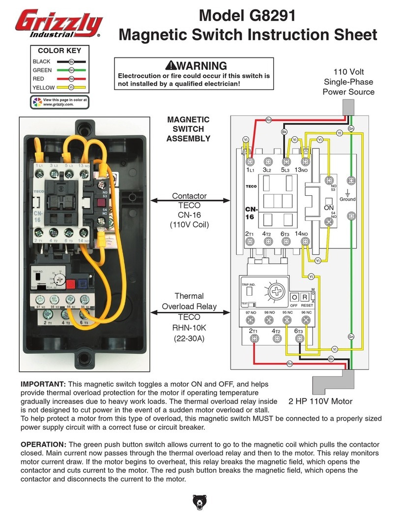
Grizzly G8291 User manual

Grizzly

Grizzly G8291 User manual

Grizzly T20551 User manual

Grizzly

Grizzly T20551 User manual

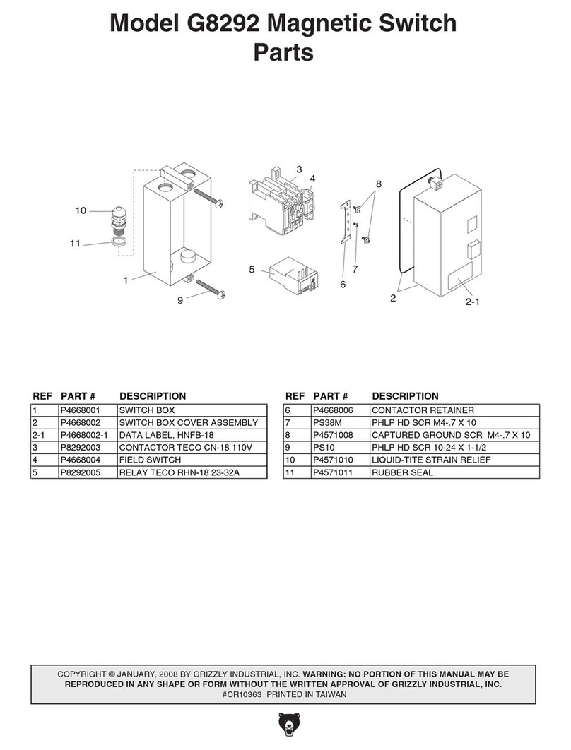
Grizzly G8292 User manual

Grizzly

Grizzly G8292 User manual

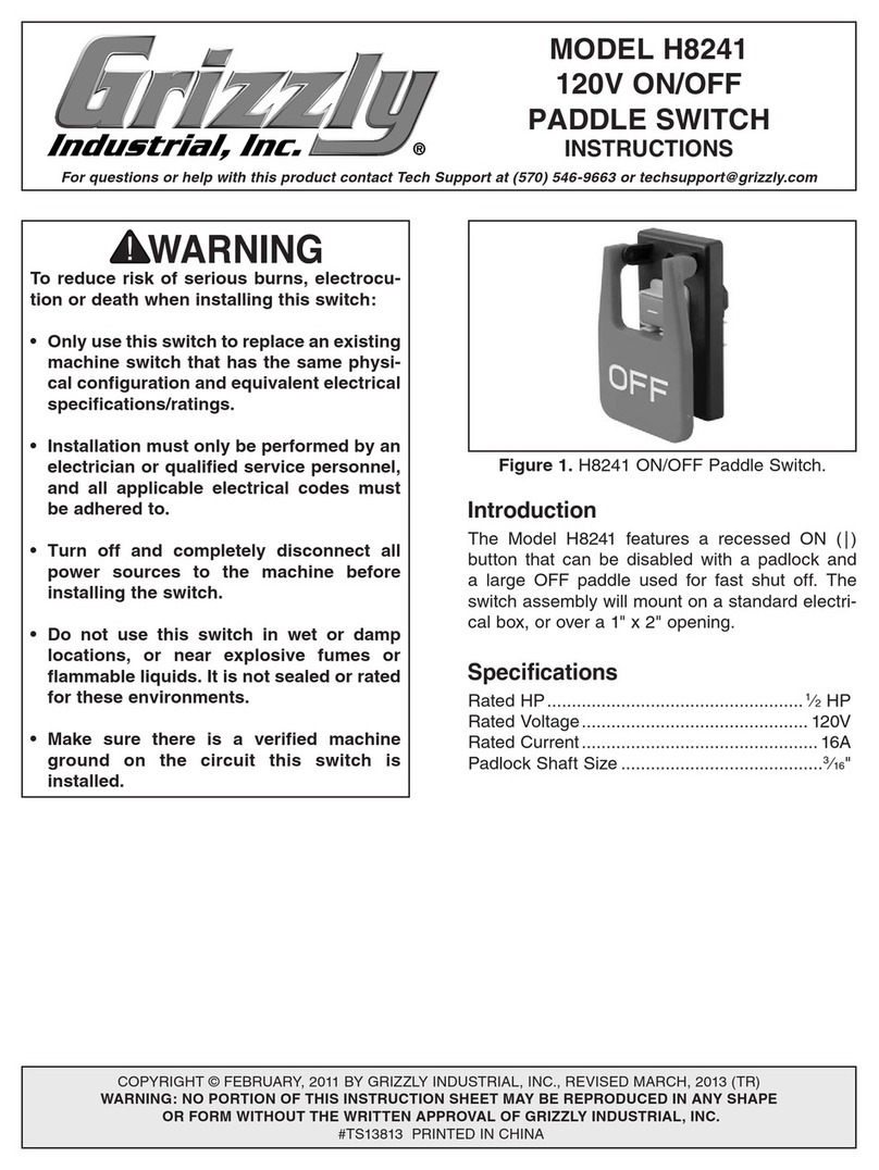
Grizzly H8241 User manual

Grizzly

Grizzly H8241 User manual

Grizzly G4672 User manual

Grizzly

Grizzly G4672 User manual

Grizzly H8239 User manual

Grizzly

Grizzly H8239 User manual

Grizzly H8246 User manual

Grizzly

Grizzly H8246 User manual

Grizzly Double Mini On/Off h8245 User manual

Grizzly

Grizzly Double Mini On/Off h8245 User manual

Grizzly G4668 User manual

Grizzly

Grizzly G4668 User manual

Grizzly T25448 User manual

Grizzly

Grizzly T25448 User manual

Grizzly G4572 User manual

Grizzly

Grizzly G4572 User manual

Grizzly G4002 Instruction sheet

Grizzly

Grizzly G4002 Instruction sheet

Grizzly G4573 User manual

Grizzly

Grizzly G4573 User manual

Grizzly G4673 User manual

Grizzly

Grizzly G4673 User manual

Grizzly G8291 User manual

Grizzly

Grizzly G8291 User manual

Grizzly G8293 User manual

Grizzly

Grizzly G8293 User manual

Grizzly G4671 User manual

Grizzly

Grizzly G4671 User manual

Grizzly H8242 User manual

Grizzly

Grizzly H8242 User manual

Grizzly G8290 User manual

Grizzly

Grizzly G8290 User manual

Popular Switch manuals by other brands

SMC Networks SMC6224M Technical specifications

SMC Networks

SMC Networks SMC6224M Technical specifications

Aeotec ZWA003-S operating manual

Aeotec

Aeotec ZWA003-S operating manual

TRENDnet TK-209i Quick installation guide

TRENDnet

TRENDnet TK-209i Quick installation guide

Planet FGSW-2022VHP user manual

Planet

Planet FGSW-2022VHP user manual

Avocent AutoView 2000  AV2000BC AV2000BC Installer/user guide

Avocent

Avocent AutoView 2000 AV2000BC AV2000BC Installer/user guide

Moxa Technologies PT-7728 Series user manual

Moxa Technologies

Moxa Technologies PT-7728 Series user manual

Intos Electronic inLine 35392I operating instructions

Intos Electronic

Intos Electronic inLine 35392I operating instructions

Cisco Catalyst 3560-X-24T Technical specifications

Cisco

Cisco Catalyst 3560-X-24T Technical specifications

Asante IntraCore IC3648 Specifications

Asante

Asante IntraCore IC3648 Specifications

Siemens SIRIUS 3SE7310-1AE Series Original operating instructions

Siemens

Siemens SIRIUS 3SE7310-1AE Series Original operating instructions

Edge-Core DCS520 quick start guide

Edge-Core

Edge-Core DCS520 quick start guide

RGBLE S00203 user manual

RGBLE

RGBLE S00203 user manual

Thrustmaster FLIGHT SIMULATOR X quick guide

Thrustmaster

Thrustmaster FLIGHT SIMULATOR X quick guide

Southwire SURGE GUARD 41390 RVC troubleshooting guide

Southwire

Southwire SURGE GUARD 41390 RVC troubleshooting guide

Buhler Nivotemp NT 61 Brief instructions

Buhler

Buhler Nivotemp NT 61 Brief instructions

Kramer VS-41HDCP user manual

Kramer

Kramer VS-41HDCP user manual

Techly IDATA AU-270 user manual

Techly

Techly IDATA AU-270 user manual

Belkin F1U109 user manual

Belkin

Belkin F1U109 user manual

manuals.online logo
manuals.online logoBrands
  • About & Mission
  • Contact us
  • Privacy Policy
  • Terms and Conditions

Copyright 2025 Manuals.Online. All Rights Reserved.

For questions or help with this product contact Tech Support at (570) 546-9663 or techsupport@grizzly.com
MODEL T33907
2-3 HP 110V 1-PHASE
MAGNETIC SWITCH
INSTRUCTIONS
COPYRIGHT © MAY, 2023 BY GRIZZLY INDUSTRIAL, INC.
NO PORTION OF THIS MANUAL MAY BE REPRODUCED IN ANY SHAPE
OR FORM WITHOUT THE WRITTEN APPROVAL OF GRIZZLY INDUSTRIAL, INC.
(FOR MODELS MFD. SINCE 05/23) #JM22728 PRINTED IN CHINA V1.05.23
***Keep for Future Reference***
3L2 5L3 13NO
2T1 4T2 6T3 14NO
110 Volt
Single-Phase
Power Source
1L1
Aoasis
CJX2
1810
Ground
2-3 HP 110V Motor
A1A2
R
E
S
E
T
ON
LA9D0909
TEST
98 NO 95 NC 96 NC
2T1 4T2 6T3
M
97 NO
S
T
O
P
A
JR28-13
Aoasis
A
12
14
16
18
R
E
S
E
T
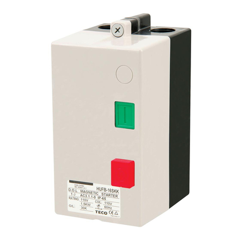
Figure 1. Model T33907.
BLACK
GREEN
RED
COLOR KEY
Bk
Gn
Rd
YELLOW
WHITE
Contactor Aoasis
CJX2-1810 (110V Coil)
Thermal Overload
Relay Aoasis JR28-13
(12-18A)
Electrocution or
fire could occur if
this switch is not
installed by an elec-
trician or qualified
service personnel!
DISCLAIMER: Color of wires shown in pictures and diagrams may not match the color of motor wires and
incoming power wires in your application. When installing this magnetic switch, consult the wiring diagram
in the motor junction box and the wiring diagram inside the magnetic switch cover.
-2- Model T33907 (Mfd. 05/23)
Thermal Relay Overload Amp
Adjustment Dial: Turn this dial
to the amperage setting speci-
fied by the motor manufacturer.
Typically, this setting is 100–
110% of the amperage load listed
on the motor data plate. Please
note that turning this dial has
no effect on increasing motor
horsepower. If turned too high,
the motor can overheat and be
damaged before the relay trips.
Manual Trip Test Lever: If the
thermal relay function is in ques-
tion, run the motor and use a
wooden toothpick to push the
red TEST button in. If motor
shuts off, thermal relay has
tripped and is functional.
Manual Contactor Override
Lug: When pushed, the
contactor is manually closed for
troubleshooting purposes only.
ON Button: When pushed,
power is sent to the magnetic
field coil, closing the contactor
and sending power to the motor.
Manual/Auto Reset Button:
In the out position, the thermal
relay is in manual reset mode.
This means you must re-install
the outside cover and push the
red OFF button, then push the
green ON button to reset the
thermal relay. In the in position,
the thermal relay will automati-
cally reset when it has cooled.
OFF Button: When pushed, the
current going to the magnetic
field coil is cut, which opens the
contactor and cuts power to the
motor.
OPERATION: When pushed, the green ON button on the outside cover of the magnetic switch energizes
a magnetic coil, which pulls the contactor closed. The main current then passes through the contactor
and thermal overload relay to the motor. The red OFF button breaks the magnetic field, which opens the
contactor and disconnects the current to the motor. A motor overload or an interruption of the power supply
will also break the magnetic field and release the contactor and disconnect current to the motor. The motor
will not restart until the overload is reset and/or the ON button is pushed.