Servicevision Scorpio 23' User manual

Servicevision Bis S.L.
Scorpio
23’
User’s manual v1.01


SCORPIO 23’ - INDEX - Basic information
Version 1.01 April 21, 2021
SERVICEVISION BIS SL
Ríos Rosas, 20 · 08940 CORNELLA DE LLOBREGAT (Barcelona) Spain · Tel. 34 93 223 86 30 · Fax 34 93 223 86 31 3
comercial@servicevision.es · www.servicevision.es
0 INDEX
0INDEX....................................................................................................................................3
1TECHNICAL INFORMATION.................................................................................................6
1.1 Basic information ................................................................................................................................. 6
1.2 Technical specifications 23’................................................................................................................. 7
2PARTS AND COMPONENTS DESCRIPTION.......................................................................8
2.1 Dolly..................................................................................................................................................... 9
2.1.1 Dolly base...................................................................................................................................................9
2.1.2 Dolly wheels..............................................................................................................................................10
2.1.3 Articulated arms........................................................................................................................................10
2.1.4 Track wheels.............................................................................................................................................11
2.2 Column............................................................................................................................................... 13
2.3 Fulcrum.............................................................................................................................................. 14
2.4 Telescopic arm .................................................................................................................................. 16
2.4.1 Main Section.............................................................................................................................................17
2.4.2 Dynamic counterweight trolley ..................................................................................................................19
2.4.3 Telescopic sections...................................................................................................................................22
2.5 Electronic box .................................................................................................................................... 26
2.5.1 Outside description of the electronic box ..................................................................................................26
2.5.2 Inside the electronic box ...........................................................................................................................29
2.5.3 Electronic components..............................................................................................................................30
2.5.4 Key concepts ............................................................................................................................................31
2.6 Hand command ................................................................................................................................. 32
2.7 Leveling head .................................................................................................................................... 33
2.7.1 Inside the Leveling Head........................................................................................................................... 34
2.8 Accessories ....................................................................................................................................... 35
3SET UP THE EQUIPMENT..................................................................................................39
3.1 Check before flight............................................................................................................................. 39
3.2 Starting the crane .............................................................................................................................. 40
4CONTROL DISPLAY INFORMATION..................................................................................42
4.1 Main screen ....................................................................................................................................... 43
4.2 Operation menu................................................................................................................................. 44
4.2.1 Limits.........................................................................................................................................................44
4.2.2 Memories..................................................................................................................................................45
4.2.3 Settings menu...........................................................................................................................................47
4.2.4 Auxiliary ....................................................................................................................................................54
5SECURITIES & RECOMMENDATIONS...............................................................................57
5.1Basic safety information..................................................................................................................... 57
5.2 Malfunction risks................................................................................................................................ 57
5.3 Potential dangers for the user ........................................................................................................... 58

SCORPIO 23’ - INDEX - Basic information
Version 1.01 April 21, 2021
4
5.4 Protection systems ............................................................................................................................ 60
5.4.1 Protection against overloads.....................................................................................................................60
5.4.2 Encoder protection system........................................................................................................................60
5.4.3 Security circuit board.................................................................................................................................60
5.4.4 Protection bars and covers .......................................................................................................................60
5.5 System shutdown .............................................................................................................................. 61
6MAINTENANCE & SERVICE...............................................................................................62
6.1 Maintenance Requirements............................................................................................................... 62
6.2 General Maintenance ........................................................................................................................ 62
6.2.1 Crane operation ........................................................................................................................................64
6.2.2 Air pressure on the dolly wheels ...............................................................................................................64
6.2.3 outside telescopic rails and rollers ............................................................................................................64
6.2.4 Inside telescopic rails and rollers ..............................................................................................................65
6.2.5 Counterweights square bearings ..............................................................................................................65
6.2.6 Counterweight cables................................................................................................................................65
6.2.7 First section cables ...................................................................................................................................65
6.2.8 Brushes of the motor.................................................................................................................................66
6.2.9 Electronic connectors................................................................................................................................ 66
6.2.10 Belts of the crane......................................................................................................................................66
6.2.11 Cable trolleys ............................................................................................................................................66
6.3 Electronic Boards............................................................................................................................... 67
6.4 Loading software to the SERVO/CCU............................................................................................... 67
6.4.1 CCU software update................................................................................................................................ 68
6.4.2 SERVO I software update.........................................................................................................................68
6.5 Driver adjustment............................................................................................................................... 69
6.5.1 Arm driver .................................................................................................................................................69
6.5.2 Leveling head driver..................................................................................................................................70
6.6 Replacement of other components in the crane................................................................................ 71
7F.A.Q. / COMMON PROBLEMS ..........................................................................................72
7.1 Possible problems related to the LH.................................................................................................. 72
7.2 Possible problems related to the electronics..................................................................................... 73
7.3 Possible problems related to the column........................................................................................... 74
7.4 Possible problems related to the counterweights.............................................................................. 74
7.5 Fuses in the electronic box................................................................................................................ 75
8SPECIAL CONFIGURATIONS.............................................................................................76
8.1 Interface with Scorpio Heads............................................................................................................. 76
8.1.1 Set up conditions.......................................................................................................................................76
8.1.2 Set up........................................................................................................................................................76
8.1.3 Back-Pan ..................................................................................................................................................78
8.1.4 Tracking mode..........................................................................................................................................79
8.1.5 Tracking tilt................................................................................................................................................81

SCORPIO 23’ - INDEX - Basic information
Version 1.01 April 21, 2021
SERVICEVISION BIS SL
Ríos Rosas, 20 · 08940 CORNELLA DE LLOBREGAT (Barcelona) Spain · Tel. 34 93 223 86 30 · Fax 34 93 223 86 31 5
comercial@servicevision.es · www.servicevision.es
8.1.6 Focus tracking...........................................................................................................................................82
8.2 Matrix mode....................................................................................................................................... 83
8.3 Record memories crane-head........................................................................................................... 83
8.3.1 Set up conditions.......................................................................................................................................83
8.3.2 Analog trigger............................................................................................................................................84
8.3.3 Digital trigger.............................................................................................................................................84
8.4 M.G. with Scorpio Focus.................................................................................................................... 85
8.5 Augmented reallity............................................................................................................................. 85
9DOCUMENTATION .............................................................................................................86
9.1 PINOUTS........................................................................................................................................... 86
9.2 Other documentation ......................................................................................................................... 88
11. Marks of the equipment..........................................................................................................93

SCORPIO 23’ - TECHNICAL INFORMATION - Basic information
Version 1.01 April 21, 2021
6
1 TECHNICAL INFORMATION
1.1 BASIC INFORMATION
The Scorpio 23’ cranes are a 3 telescopic sections cranes with a dynamic counterweight system to
compensate the balance weight during motion. They are capable to perform smooth movements in
high and slow speed with reduced noise of the telescopic arm movement.
It is possible to mount any kind of head up to 70kg including camera package in the underslung
position. There is also the possibility to mount the leveling head in the over slung position to get more
lens high with 35kg of maximum payload for the head and the camera package in this configuration.
The range of movement on the Tilt axis (100º of movement, 50º up from the horizontal position and
50º down) allows the Scorpio 23’ cranes to get an amazing high lens in a small footprint which makes
it perfect for any situation.
The dollies are prepared for mounting gripping bars to push the crane along 1m dolly tracks or use
the articulated arms from the dolly to adapt it to 62cm tracks or even collapse it more to fit the crane
in those hard-to-get places for bigger cranes.
The features incorporated in the electronic box, such as Arc Compensation or program limits on the
movement of the arm, makes this crane the best option for those shots that require a hard level of
coordination between different members of the crew. The possibility to record movements and play
them back as many times as needed with high precision makes this crane a good option for repetitive
movements scenarios.
The new external display allows to operate from both sides of the crane while being able to see all
the information data displayed on the screen (arm range, height of the optic, pan, and tilt degrees…).
The Scorpio cranes match perfectly with any Scorpio Head. This combination of head and crane
can work together allowing the user to perform features such as back pan for regular heads or the
tracking feature: the possibility to set one point in space and lock the head in that point while the arm
moves around.

SCORPIO 23’ - TECHNICAL INFORMATION - Technical specifications 23’
Version 1.01 April 21, 2021
SERVICEVISION BIS SL
Ríos Rosas, 20 · 08940 CORNELLA DE LLOBREGAT (Barcelona) Spain · Tel. 34 93 223 86 30 · Fax 34 93 223 86 31 7
comercial@servicevision.es · www.servicevision.es
1.2 TECHNICAL SPECIFICATIONS 23’
Max length: 7,1m (23’)
Min. length: 1,5m (5’)
Back length of the arm: 1,85m (6’)
Telescopic Range: 5,6m (18’)
Max. optic height: 6,7m (21’)
Telescopic column range: 0,3m (1’)
Payload in Underslung: 70kg (154lbs)
Payload in Over slung: 35kg (77lbs)
Power requirements: AC 220 v/ 16 A
AC 110 v/ 20 A
Output power for head: DC 30 v/ 20 A
Output power for monitor: DC 12 v/ 3 A
Speed of the arm: 1,8 m/s
Weight of the crane empty: 600kg. (1322.8lbs.)
Max. Weight when loaded: 1100kg. (2425lbs.)
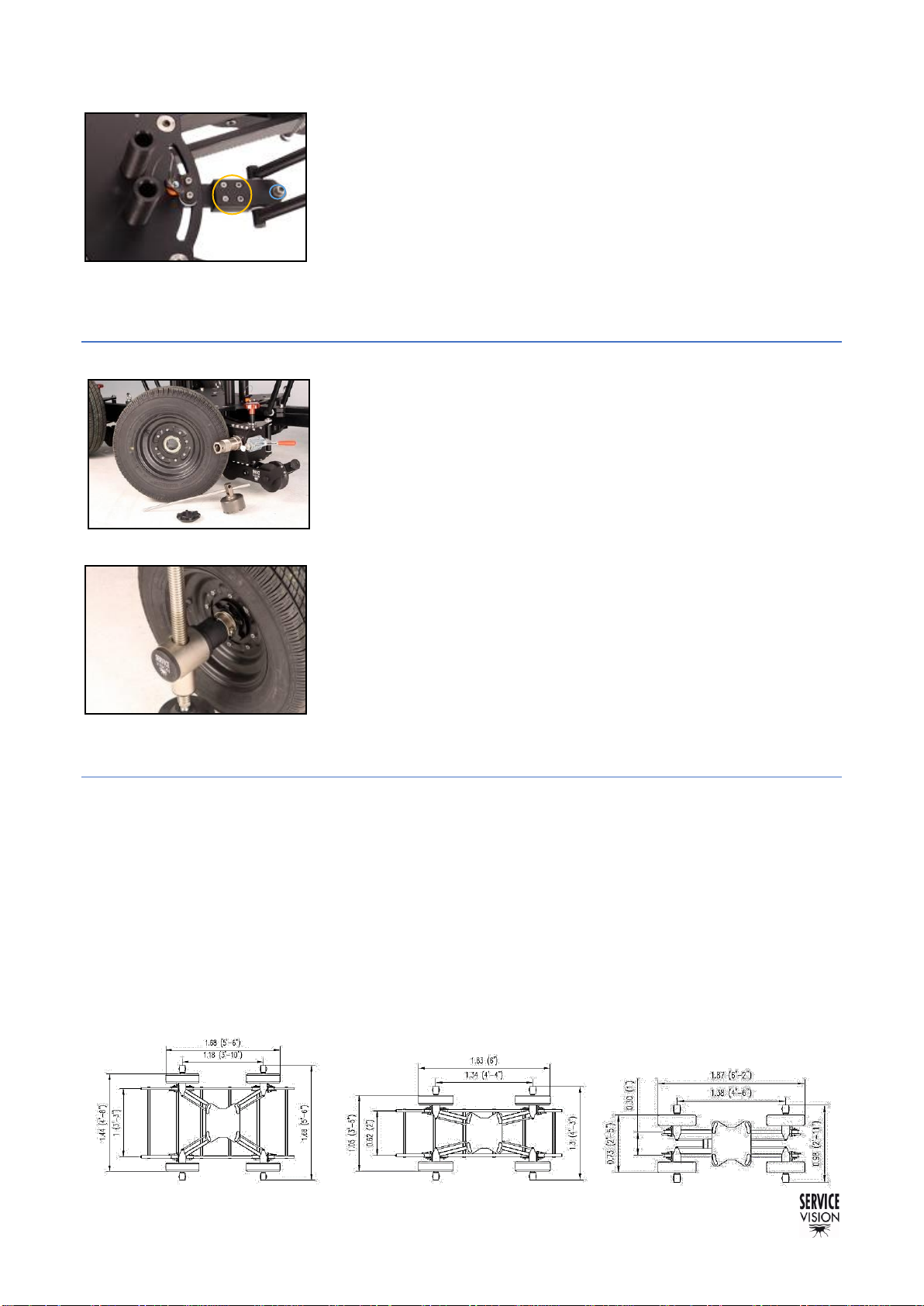
1 m (3’ 3’’) TRACKS
0,62 m (2’) TRACKS
SMALLEST CONFIGURATION
(FOR TRANSPORT ONLY)

SCORPIO 23’ - PARTS AND COMPONENTS DESCRIPTION - Technical specifications 23’
Version 1.01 April 21, 2021
8
2 PARTS AND COMPONENTS DESCRIPTION
This is a general view of the components on the SCORPIO 23’ cranes:
The dolly is the part that locates the crane in the position where it will be operated, either with the
travelling wheels or the dolly wheels and the steering handles.
The Column holds the arm and can be extended or retracted manually to the desired high of the
arm to perform different movements depending on the needs of the user.
The fulcrum is where the arm pivots inthe pan and tilt axes. The information regarding themovement
of the arm is gathered from here.
The Telescopic arm can be extended or retracted using the hand command in order to reach
different positions for the remote head. It has a counterweight support to keep the arm balanced in
any position.
The Electronic box is the main brain of the crane. All the electronic components are located in the
Electronic box and the Leveling Head.
The Leveling Head holds the level automatically when the telescopic arm moves up and down.
The Dynamic Counterweight System allows to fine tune the balance of the arm in any point of its
extension.
Beside the crane, there are some accessories that are needed in order to operate the crane and to
do regular maintenance of the crane. In the following chapters there will be a brief description of every
component of the crane and the adjustments that can be done by the user.
2.01 Parts of the crane
Leveling Head
Column
Dolly
Fulcrum
Dynamic Counterweight
Telescopic arm
Electronic box

SCORPIO 23’ - PARTS AND COMPONENTS DESCRIPTION - Dolly
Version 1.01 April 21, 2021
SERVICEVISION BIS SL
Ríos Rosas, 20 · 08940 CORNELLA DE LLOBREGAT (Barcelona) Spain · Tel. 34 93 223 86 30 · Fax 34 93 223 86 31 9
comercial@servicevision.es · www.servicevision.es
2.1 DOLLY
2.1.1 DOLLY BASE
The dolly is the base of the crane, it can be pushed with 48mm or
50mm Aluminum pipes attaching them into the supports (A in
fig.02.03) by tightening the white knobs in the supports. These
supports can also be used as a storage point for the Leveling Jacks
of the dolly. There are 4 supports for pushing bars, two per side. The
dolly also has four supports in the center base (B on fig.02.03) to put
the leveling jacks when they are not used.
It has four strap rings on the corners of the base to secure the
telescopic arm into the dolly when the arm is mounted.
The threads in the dolly (A in fig.02.04) and the guiding pins (B) are
used to attach the column to the dolly. In the chapter 9
Documentation there is a drawing of the column attachment base.
The Scorpio 23’ has two independent steering handles (C in
fig.02.03) and pneumatic wheels that allow the movement of the
crane through tight corners. The steering handles can be locked by
introducing the locking pin (D10x30mm) in the locking position (D in
fig.02.04). There is a storage position for the locking pin in case it is
not locking the direction.
Note: Do not lift the crane from the strap rings of the dolly.
If the crane needs to be lifted, strap it under the chassis.
02.02 Dolly
C- Rings for straps
B- Guiding pin for the column
A- Threads for the column
2.04 Dolly top components 2
D- Locking pin for steering
A- Supports for pushing bars
02.03 Dolly top components 1
B–Leveling Jacks supports
C- Steering handle
SCORPIO 23’ - PARTS AND COMPONENTS DESCRIPTION - Dolly
Version 1.01 April 21, 2021
10
It is possible to easily remove the steering handle by unscrewing the
4 screws next to the steering lock screw on the steering handle
support. The friction screw is used to apply friction on the vertical
movement of the steering handle.
2.1.2 DOLLY WHEELS
The wheels are attached to the dolly with castle nuts. On the inner
side of the hubs there are the pressure brakes of the wheels (red
handles). The holes inside the hubs shafts are prepared to receive
the leveling jack’s shaft and, once in place, with the locking
pin(08x60mm) they are locked in place (fig.02.07). To assemble the
wheel introduce it intothe shaft and lock it withthe nut usingthecastle
tool provided.
There is one leveling jack for each wheel. To move the crane
around, they can be removed to reduce the width of the base. To
operate the crane, the 4 of them need to be touching the ground and
they may be used to level the base. To introduce the leveling jack,
remove the locking pin, introduce the axis of the jack through the hole
inside the shaft of the wheel and lock it in place with the pin. Then
bring the pad down using the 24mm ratchet wrench provided with the
crane or the steering wheel.
2.1.3 ARTICULATED ARMS
The Scorpio 23’ has three possible configurations for the dolly’s articulated arms:
Option A is for 1m. / 3.3 ft. wide tracks and high-speed movements. It is the widest and therefore
makes the crane most stable.
The option B is for 62cm / 2 ft. wide tracks and normal speed movements.
The option C is the narrowest and may only be used to pass the crane through doorways. In this
configuration it is forbidden to use the crane to shoot. The base is not stable enough to allow any arm
movement. The crane is top heavy and will topple over. In this configuration, the steering can only
turn a few degrees in either direction because of the width of the wheel arms.
A–Screws to hold the steering.
B–Friction screw.
02.05 Dolly steering detail
02.06 Wheel dismounted.
02.07 Leveling jack locked.

SCORPIO 23’ - PARTS AND COMPONENTS DESCRIPTION - Dolly
Version 1.01 April 21, 2021
SERVICEVISION BIS SL
Ríos Rosas, 20 · 08940 CORNELLA DE LLOBREGAT (Barcelona) Spain · Tel. 34 93 223 86 30 · Fax 34 93 223 86 31 11
comercial@servicevision.es · www.servicevision.es
To change the dolly from one configuration to another, the telescopic
arm needs to be strapped to the dolly (or removed). If the arm is
assembled, it is not needed to remove the counterweights and the
remote head, but the arm needs to be completely retracted to change
the configuration of the wheel arms. The four levelling jacks must be
mounted on the wheels. Lift the dolly with all the levelling jacks except
one until you can turn the respective arm´s wheel. Be careful as the
crane is slightly unstable during the operation. Remove the screw that
holds the wheel’s arm in place using the 24mm ratchet spanner. Using
your hands, move the wheel’s arm to the new position and fix the
screw back in place. Lower the respective levelling jack now until the
pad touches the ground. Repeats the same operation with the three
other wheel’s arms.
2.1.4 TRACK WHEELS
The dolly can be used in different tracks depending on the arms configuration. To do this, the track
wheels need to be mounted into the dolly as shown in this chapter:
To fix or remove the tracking wheels they need to be introduced
under the chassis of the dolly, next to the wheels with the positioner
pin (A in fig. 02.11).
Once the pin is introduced it can be locked by screwing the red knob
on top of it (C). In case it is needed, this red knob can be removed by
pulling it out and unscrewing it at the same time.
Once the track wheels are assembled, the crane can be introduced
into the tracks using a ramp. In case the user wants to stop the dolly
in any position, there are brakes on each track wheel to lock it in place.
The levelling jacks can also be used as brakes.
Note: Ensure that the track is leveled before mounting the
crane on it.
Note: Remember that the smallest configuration is only for
transport, it is not safe to operate the crane with the dolly in
this configuration.
02.08 Rachet wrench on the arm screw.
02.09 Changing the position of the arm.
02.10 Arm’s new desired position.
02.11 Inner side of the wheel.
A–Positioner for the track wheels.
B–Brake for the track wheels.
C–Locking knob.
02.12 Track wheel assembled.

SCORPIO 23’ - PARTS AND COMPONENTS DESCRIPTION - Dolly
Version 1.01 April 21, 2021
12
Notice before assembling the track wheels that there are 2 of them
with a movable axis side to side and 2 fixed. This is to correct the
minor differences between both sides of the track. To make this
system work properly, mount the same kind of track wheels (movable
or fix) at the same dolly’s side.
Important note: When using the travelling wheels, DO NOT
leave the crane mounted in tracks overnight, the track wheels
may get flat if they are left for long periods of time in the same
position.
02.13 Different track wheels
SCORPIO 23’ - PARTS AND COMPONENTS DESCRIPTION - Column
Version 1.01 April 21, 2021
SERVICEVISION BIS SL
Ríos Rosas, 20 · 08940 CORNELLA DE LLOBREGAT (Barcelona) Spain · Tel. 34 93 223 86 30 · Fax 34 93 223 86 31 13
comercial@servicevision.es · www.servicevision.es
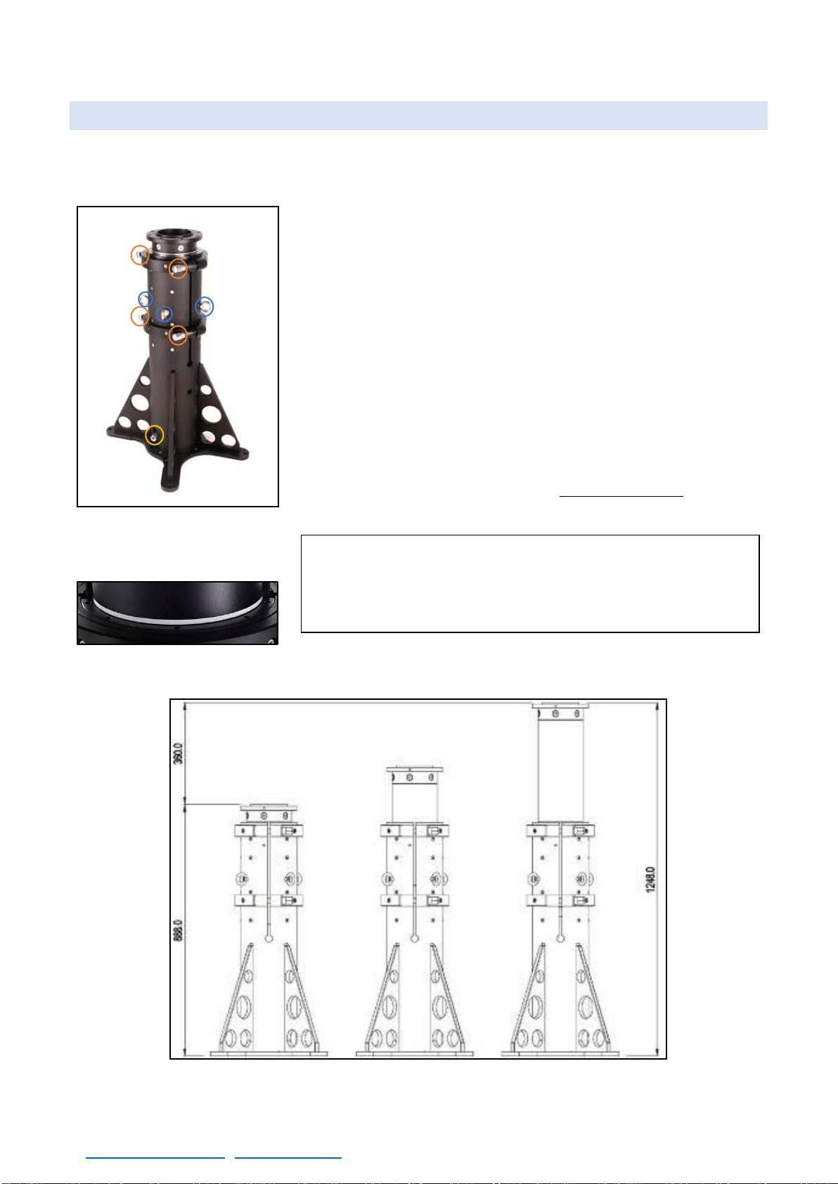
2.2 COLUMN
The SCORPIO 23´arm is supported by a 90 cm / 3ft. high column. This column is made up of a main
column with a telescopic section inside it. It can be raised 40cm / 1.3ft. This can be done with a 1kW.
drilling machine.
The column has a flat base. It can therefore be fixed to any properly
designed structure such as camera cars, trusses, etc.
It is attached to the base of the dolly with 4 screws and there is only
one position to assemble it (using the guiding pins on the dolly).
To change the height of the column, loose the column bracer nuts
(B in fig. 02.14) and use the column lifting mechanism to do so (A).
The column lifting mechanism can be operated using a 24mm rachet
wrench or a 1kW drill with the drill adaptor provided with the crane.
There is a white mark in the limit of the column section so the
operator can visually see when the limit has been reached and stop
telescoping the column out. Once the desired high is achieved, tight
the column nuts again by cross tighten both sides equally.
Note: In case the arm is already assembled, before lifting
the column, balance the arm with the CW carriage in the
center of the column, remove the arm straps, fix the pan and
tilt brakes and ensure the column bolts are loose.
02.14 23’Column
A–Column lifting point.
B–Column bracer nut.
C–Column rings.
02.15 Visual limit column mark.
02.16 23’Column measures.
SCORPIO 23’ - PARTS AND COMPONENTS DESCRIPTION - Fulcrum
Version 1.01 April 21, 2021
14
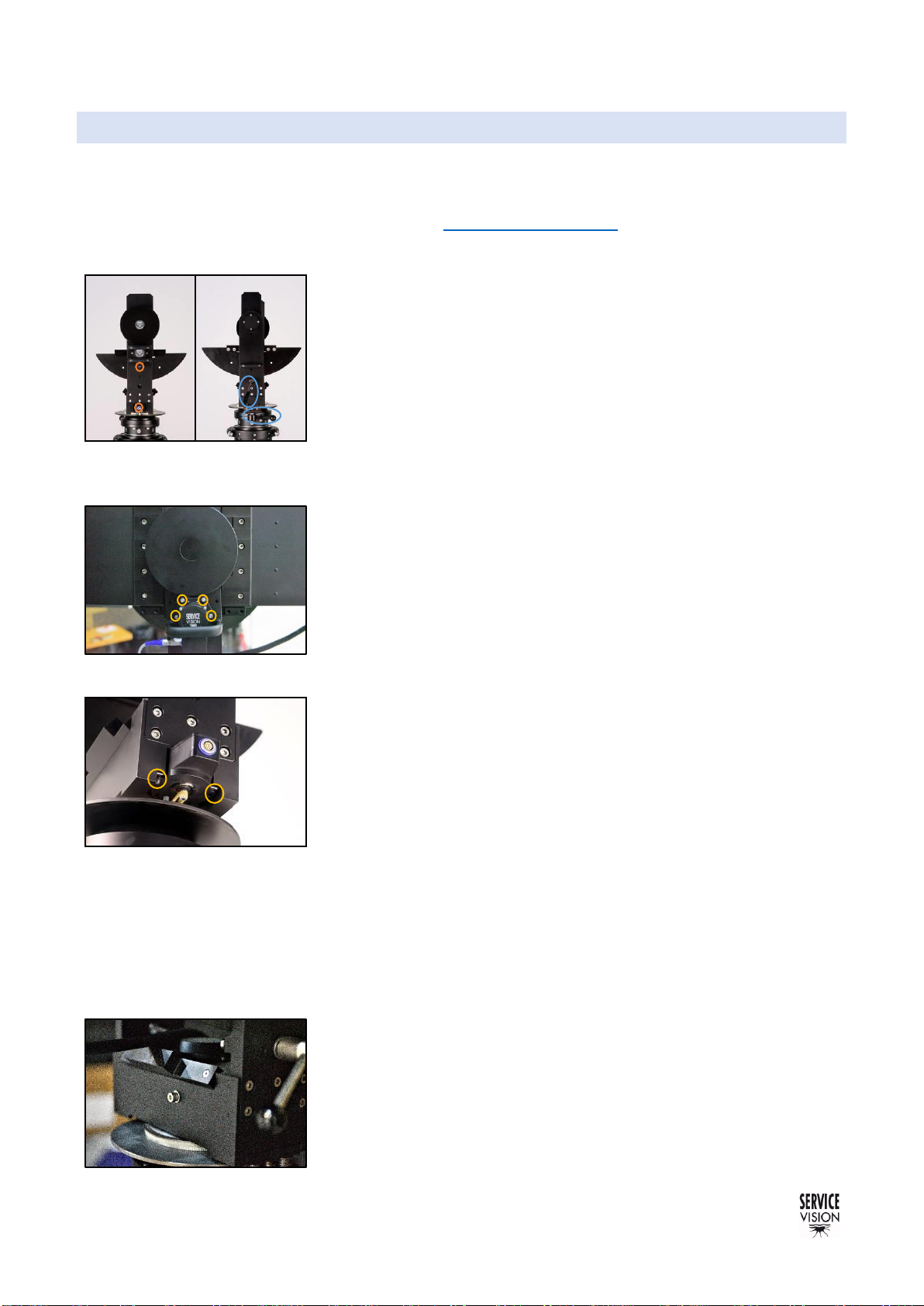
2.3 FULCRUM
The fulcrum is where the Scorpio 23’ arm pivots in pan and tilt axes.
It is attached to the column with 8 screws (DIN 912 M10x35mm). It is possible to attach the fulcrum
in a different structure with a flat base. On the chapter documentation there is a drawing of the flat
base of the fulcrum.
The fulcrum has encoders on the right side connected to the
Electronic box. Those encoders inform the E.B. when the user
changes the position ofthe arm and that information is used to display
data in the portable display or to perform features as the Arc
compensation or the motion generator among other functions.
Both encoders give the same signal and have the same pinout. For
troubleshooting they can be swapped to check if the signal in the
electronic box is received. The cables for the encoder also have the
same pinout but different color. The differences are the housing and
the color code of the connector (blue for tilt and grey for pan).
To replace the tilt encoder belt, remove the cover on top of the tilt
encoder and the four screws holding the encoder (fig. 02.18). The belt
will be free. To apply tension to the belt, loose the four screws from
the encoder, pull it down until the desired tension and tight the screws
again.
To replace the pan encoder belt, remove the cover in the center of
the fulcrum to have access to the KE nut. Remove this nut and the
pan brake mechanism (the Pan brake needs to be dismounted by
unscrewing the knob completely and removing the 2 screws aside the
knob). Now loose the two screws holding the pan encoder (fig. 02.19)
and pull the fulcrum up to have access to the belt. Once replaced,
mount everything again and use the two screws of the encoder to
apply tension to the belt.
•Commercial reference for encoder belts: T2.5 600
The brakes are activated with the knob handles located in the left side of the fulcrum (B in fig.02.17).
It is a brake pad system and is tightened by moving the handle clockwise. The handle can be pulled
out to disengage it and engage it again in another position to be able to apply more tension if needed.
The brakes are not blockers: when they are used, the arm is just hold in place by friction pads and it
can be moved if the force applied to move it is stronger than the friction of the pads.
On top of the brakes side, next to the pivot axis there is the screw
for the tilt friction. If the user wants to adjust the friction on the tilt axis
this screw can be tight to stiffen the tilt movement or loosen to make
it softer. The pan axis adjustment can be done in the bottom part of
the fulcrum (fig. 02.20).
A–Encoder connectors.
02.17 Fulcrum.
B–Brakes for pan and tilt.
02.20 Pan friction screw.
02.18 Screws holding the tilt encoder.
02.19 Screws to hold the pan encoder.

SCORPIO 23’ - PARTS AND COMPONENTS DESCRIPTION - Fulcrum
Version 1.01 April 21, 2021
SERVICEVISION BIS SL
Ríos Rosas, 20 · 08940 CORNELLA DE LLOBREGAT (Barcelona) Spain · Tel. 34 93 223 86 30 · Fax 34 93 223 86 31 15
comercial@servicevision.es · www.servicevision.es
The 23’ arm is held onto the fulcrum by two clamping guides which are in the center of the crane
arm. The clamps have a sliding plate with two screws which are used to clamp the guide between
them.
These screws must always be tight while the crane arm is on the
fulcrum. There is only one position to mount the arm since both sides
of the fulcrum have different widths.
02.21 Fulcrum’s sliding plate.

SCORPIO 23’ - PARTS AND COMPONENTS DESCRIPTION - Telescopic arm
Version 1.01 April 21, 2021
16
2.4 TELESCOPIC ARM
The arm of the craneis made up of different aluminum sections that extendsor retracts automatically
controlled by an operator with the Hand Command. In this chapter we will focus on the arm itself, the
mechanics in it and how to strap it safely.
Underneath the front end and the
rear end of the main section there are
two horizontal holes. These, with a
50mm round bar put through them,
can be used to lift the crane arm when
mounting and dismounting it from the
fulcrum.
To mount the arm into the fulcrum it needs to be lifted using a forklift
or a similar device that can lift the arm and insert it into the fulcrum.
From the factory, the cranes are shipped inside a box with 2 straps
marking an alternative lift point for future references.
Once assembled, the arm must
always be strapped to the dolly base
rings via the adjustable ratchet straps
provided with the crane. The strapping
points are shown in the fig. 2.25, 2.26,
2.27. Notice that when the arm is
empty is always heavier in the rear
part of the arm.
The strap from the leveling head is to prevent that the telescopic
sections extend while it is being transported. The strap in the leveling
head needs to be used as shown in fig. 02.27 in order to do not
damage the mechanism in the leveling head. Never strap it in the
movable part of the leveling head.
On the top rear part of the arm there is a screw used to block the
arm when is shipped overseas. This screw lifts the inside parts to
reduce the pressure to the inner wheels. Remove this screw to be
able to move the telescopic sections in and out.
This blocker can also be used to prevent that the telescopic sections
extend while the crane is being transported.
02.27 Leveling Head strap to front
strap point.
Note: The ratchet straps can only be safely removed once
the crane arm is completely balanced.
02.22 Front support for bars.
02.23 Rear support for bars.
02.25 Rear strap point.
02.26 Front strap point.
2.28 Telescopic sections blocker.
11.18 Lifting the arm.

SCORPIO 23’ - PARTS AND COMPONENTS DESCRIPTION - Telescopic arm
Version 1.01 April 21, 2021
SERVICEVISION BIS SL
Ríos Rosas, 20 · 08940 CORNELLA DE LLOBREGAT (Barcelona) Spain · Tel. 34 93 223 86 30 · Fax 34 93 223 86 31 17
comercial@servicevision.es · www.servicevision.es
The arm of the SCORPIO cranes is made up of a main section, fixed, and four telescopic sections.
These tubes are made by extrusion from one block of aluminum and give to the crane the rigidity
needed toperform movements of the camera from 1.50m/5’ when the arm is fully closed to 7.10m./23’’
in the maximum length.
The basic components of the telescopic arm are the dynamic counterweight carriage, the levelling
head, the electronic box, which controls the system, the power unit for the Scorpio Heads, the
protection bars and the counterweight supports.
2.4.1 MAIN SECTION
The Main section is the fix part that holds the rest of the components detailed before. Underneath
of it there are 2 support legs in the front part and 2 wheels in the rear part to rest the arm in case the
electronic box and the Leveling Head are not mounted.
There are 2 guiding supports, in front and in the back of the crane
to hold the Power Unit for Scorpio Heads (fig.02.30) and the
Electronic Box from the crane. To mount the Power Unit, remove the
stopper screws from the guides and slide it in with the XLR
connectors facing the rear part of the crane.
To mount the electronic box, remove the screws from the sliding
guides (fig. 2.31) and slide the EB with the main AC connector facing
the front side of the crane. Do not do this operation alone, the
Electronic Box is heavy.
02.29 Scorpio 23’ Arm retracted.
02.30 Scorpio 23’ Power Unit assembled.
02.31 Locker screw for Electronic box.

SCORPIO 23’ - PARTS AND COMPONENTS DESCRIPTION - Telescopic arm
Version 1.01 April 21, 2021
18
2.4.1.1 INSIDE THE MAIN SECTION, MOVING THE FIRST SECTION
Inside the main section there is located the motor of the arm. This
motor has an encoder attached to it to control the position of the
crane. The motor is held with 4 screws into the gearbox. This gearbox
is attached to two drums, one on each side of the main section. This
motor transmits the movement into a gearbox and this one makes
the two drums to coil in one or other direction.
Into each drum there are two cables attached: when one is coiled,
the other uncoils. These cables are rolled one faced against the
other, one from the top part of the drum and the other from the
bottom. The end of the bottom cable is attached into the back of the
First section (the first telescopic section). When the drum coils the
cable, the First section is pulled inside.
To extend the first section, the
upper cables from the drum pass
through a pulley attached into the
main section and ends in the
attachment showed in fig. 02.35
from the First section. So, when the
drum coils the cable, the first section
goes out pulled by these cables.
To know where the telescopic limits of the crane are, the Scorpio
cranes have two magnetic sensors attached into the main section.
These magneticsensors are onlyused when the crane is started (see
chapter 3.2 Starting the crane). They will give to the system the
reference position of the telescopic movement. Only one of these
limits needs to be detected by the crane and the system will
automatically know what the range of movement for the telescopic is.
When the First section is retracting,
it approaches the magnet (fig.02.38)
into the retracted sensor (fig.02.33).
When the First section extends, the
counterweight trolley moves back
and approaches the magnet
(fig.02.37) into the extension limit
(fig.02.36).
Note: All the cable ends have a double nut safety lock. To
see how to tight the cables go to chapter 6 Maintenance.
02.32 Motor for the arm.
B–Motor for the arm
A–Screws for the motor
C–Magnetic limit
02.33 End of retracting cable.
B–Magnetic limit
A–End of the drum cable
02.35 End of the extension cable.
02.34 Pulley for the main cable.
02.36 Extension sensor.
02.38 Magnet in the first section
02.37 Magnet in the counterweights

SCORPIO 23’ - PARTS AND COMPONENTS DESCRIPTION - Telescopic arm
Version 1.01 April 21, 2021
SERVICEVISION BIS SL
Ríos Rosas, 20 · 08940 CORNELLA DE LLOBREGAT (Barcelona) Spain · Tel. 34 93 223 86 30 · Fax 34 93 223 86 31 19
comercial@servicevision.es · www.servicevision.es
The magnetic limits are connected on top of the motor. From there
the cable for the limits is joined with the cable from the motor to be
connected into the electronic box.
2.4.1.2 COUNTERWEIGHT SUPPORTS
There are two fix supports for counterweights in the main arm, one in the front and one in the back.
These supports are used to mount counterweights on them in order to make the fix balance of the
crane (see chapter 3.2 Starting the crane).
The Rear-Counterweight Holder is located at the back of the main
section of the Crane Arm. It consists on a platform to slide the weights
in and a screw with a red locking nut that is used to fasten the different
counterweights provided with the crane in order to balance it.
The Front-Counterweight Holder is located at the front top part of the
main section. It consists of a platform to slide the weights and one
screws with a red locking nut used to hold in place and fasten the
different counterweights provided with the crane in order to balance it.
2.4.2 DYNAMIC COUNTERWEIGHT TROLLEY
The SCORPIO 23’ has a movable counterweight trolley that
balances the crane when the telescopic sections retract or extend.
This movable counterweight is attached to the First section with 4
cables that work as a closed loop using a pulley system in the front
part of the main arm and a regular pulley in the back. When the First
section extends, the CW (Counterweight carriage) moves to the back
of the crane.
The weight holders on the weight carriage will be used to
counterbalance the telescopic crane arm while it´s moving. It consists
of an inverted metallic “U” that is connected to the moving carriage on
the Crane Arm. The U is fixed to the carriage with 2 nuts (DIN912
M12x40mm) and it has two “male” supports, one per side which fits
into the “female” part of the counterweights.
02.39 Connector for the limits.
02.40 Rear counterweights support.
02.41 Front counterweights support.
02.42 Telescopic counterweight trolley.
02.43 Center position of the telescopic.

SCORPIO 23’ - PARTS AND COMPONENTS DESCRIPTION - Telescopic arm
Version 1.01 April 21, 2021
20
The counterweights are fastened onto the weight holders by two
screws. These screws have an intermediate locking nut to be able to
tighten different amounts of weights easily. These screws have two
locking positions (fig. 02.44).
The maximum number of weights can be told by the length of the
male positioner on the “U”. This maximum amount can never be
exceeded.
One of theparticularities of thedynamic counterweight system is that
the counterweights support can move automatically inside a small
range of movement to make a better balance of the telescope.
There are physical limits (fig. 02.45) used to detect the mechanical
end of the range of movement.
When the crane starts, the motor of the counterweights will move a
belt attached to the gear at the end of the endless screw. This will
slide the CW support in both directions to detect these limits. Once
both limits have been detected, the motor will move the CW support
in the center of the range of movement. The position of this CW
support can be controlled by the system to assign different positions
of the CW support to different positions of the arm length in order to
get a better balance of the crane in any circumstance.
In case the user wants to move manually the position of the CW inside the trolley, there is a red
switch with three positions (fig. 02.46): S, B and M. S means the motor is controlled by the Servo
(normal operation). To move the counterweights to the desired position the crane needs to be started
with the switch in M (for manual). This will detach the motor brake and allow the user to move the
endless screw using an Allen key at the end of the axis (fig. 02.45). Once the counterweight trolley is
in the desired position, change the switch to B. This will force the
motor to hold that position and prevent it moves when the crane is
tilted.
All this system of motor and mechanical limits is connected to the
electronic box with one single cable that comes from the trolley to the
electronic box inside a chain.
The motor for the counterweights transmits the movement using a
belt. To apply tension to this belt, remove the cover shown in picture
(fig. 02.46), loose the 4 screws holding the motor and move the motor
to apply tension. To remove the belt, loose enough the motors screws
and simply pull the belt out.
•Commercial reference for CW belt: T5 425
Note: The crane can never be used without all the Weight
Fastening Screws and nuts securely fastened.
02.44 Locking counterweights screw.
02.45 Physical limit for the dynamic
counterweights system.
02.46 Operation switch for the
counterweights.
02.48 Counterweights belt.
02.47 Connectors for the dynamic CW.
Table of contents
Other Servicevision Camera Accessories manuals


