SERVO D-1000X User manual
PLEASE READ THE OPERATION MANUAL BEFORE USE.
KEEP THE MANUAL AND INSTALLATION DIRECTIONS FOR REFERENCE.
INDEX
WARNINGS BEFORE INSTALLATION
INSTALLATION
OPERATION
MAINTENANCE
TROUBLE SHOOTING
OUTSIDE DIMENSIONS
ACCESSORIES & PARTS LIST
PARTSLIST
INSTALLATION & OPERATION MANUAL
MODEL:D-1000X
D-1000XLD
D-1000Y
D-1000Z
D-1000YLD

WARNINGS BEFORE INSTALLATION
Pleasebesurethe powerisoffbeforeinstallation. Donot connect thepowertable feedto
thepower toavoidan accident duringinstallation.
Thispowertable feedrequiresAC120V 50/ 60Hzelectricalservice. Please besuretheinput
poweris incompliancewiththis requirement. Ifthe input powerisnotAC120V50/60Hz, please
usean appropriatetransformer. Failuretouse thecorrectpower will damagethepower feed
andcan createadangerous condition resultingininjury ordeath.
Exceptthe forconsumableparts or maintenanceparts,do notdisassemblethepower tablefeed.
Openingthe powerfeedmay cause injurytooperator ordamagetomachine andwillinvalidate
thewarranty.
1
INSTALLATION
Step1:Gathertogetherthefollowingitemsthatyouwillneedto complete this installation.
a)Softhammer
b)3/4"socketwrench
c)Setofinchhexwrenches
d)Grease
e)Cleanshoprag
Step 2:Movethetabletotheextremeleft.
Step 3:Removethenut,handle,anddialassemblyfromthe right-hand end of thetable.
Step 4:Removethefourcapscrewsholdingthebearinghousingin place.
Step 5:Usingasofthammer,tapthebearinghousingoff.Cleantheendsurfaceof the
table.
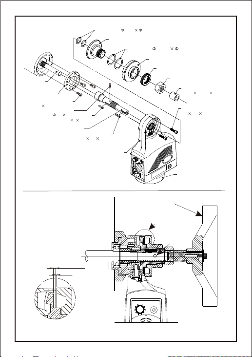
D-1000X & D-1000XLD REPUBLIC LAGUN
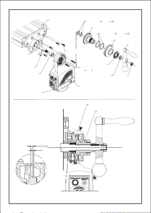
PREPARATION
Step 1:Withthetableintheextremeleft-handposition,installthe adaptor with the four
capscrews.
NOTE:Onsomemachinesthedrivepinholesdonotline up with the adaptor.
Removeanddiscardthepinsinsuchcases.Thefourcapscrewsareall that is necessary.
Step 2:Slidethebearingraceontotheleadscrew.
Step 3:Slidethepowerfeedontothebearingraceandpush flush to the endofthe
adaptor.
SecurewithtwoM6XP1.0X25mmlongsocketheadcapscrews.
POWER FEED INSTALLATION
BEVEL GEAR INSTALLATION
Step 1:Installshimwashers,approx..080thick.SeeFig.A
Step 2:Installkey,bevelgear,andcrank handle.
Note: With feed in neutral turn hand crank. If it turns freely in one direction
but catches in the other direction backlash is too large.
If rough engagement of gear is heard or felt in both directions you
probably require additional shims.
2
A
MUSTHAVECLEARANCE
MORETHAN0.080"
USE07177HANDLEWASHER IFREQUIRED
<FIG.A>
0.080-0.085"
0.005"
D-1000XLD 59331BEVELGEAR (LAGUN)
1169DIAL(LAGUN)
HANDLE
DIALNUT
LARGESHIM( 1-23/32" 1-5/16")
SMALLSHIM( 1-1/32" 5/8")
NUT
SCREW
(M6P 1.02 5(mm))-2pcs
X-AXISADAPTOR
LEADSCREW
X-AXISBEARINGRACE
POWERTABLEFEED
WORKTABLE
KEY
EXISTINGSCREW-4pcs
BOTTOMCOVER
BEVELGEAR
DIAL
HANDLEWASHER

3
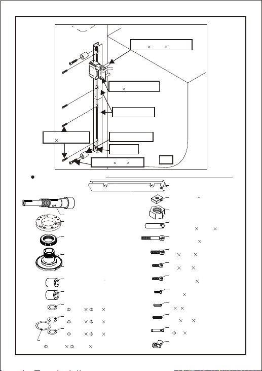
LIMIT SWITCH INSTALLATION
Step 1:Remove thestandardtable stop piecesandinstall thetablestoppieces furnished.
Putthestandardstops backinaposition topreventfeed stops frombeingset
beyondextremetabletravel.
Step 2:Remove theT shapedtablestop andinstalllimitswitch usingexistingscrews.
Aspacermayberequiredto spacelimitswitchfrom table.
NOTE
Step 1:For properoperation,the electrical limitswitchshould beengaged0.4inch
before the mechanicalstopto allowforcoastingof thetable.
Step 2:Put thecableclamp on thecableand securetotheright-hand chipscraperscrew.
Step 1:Aftergettingthepropergear backlash,thedial should beadjustedto obtain.005"spacing
from the faceofthe powerfeed.
This isimportantin ordertokeepchips fromenteringthegear train.
Washersareprovided forthis.Shimas required.
Step 2:In thefollowingsequence, replace thekey(if removed),dial,anddial-locking nut.
Slide the handleinplace andtightenwithsupplied nut.
DIAL AND HANDWHEEL INSTALLATION
EXISTINGSCREW-2pcs
CABLETIETOBRACKET
07237T-NUTS-2pcs
07164LIMITSTOP-2 pcs
59332(LAGUN)
SCREW
(M8P 1.253 0(mm))-2pcs
07253L/SCOVER(1)
07254L/SSPRINGS(2)
07252L/SBRACKET(1)
1000 L/SBRACKET(LAGUN)
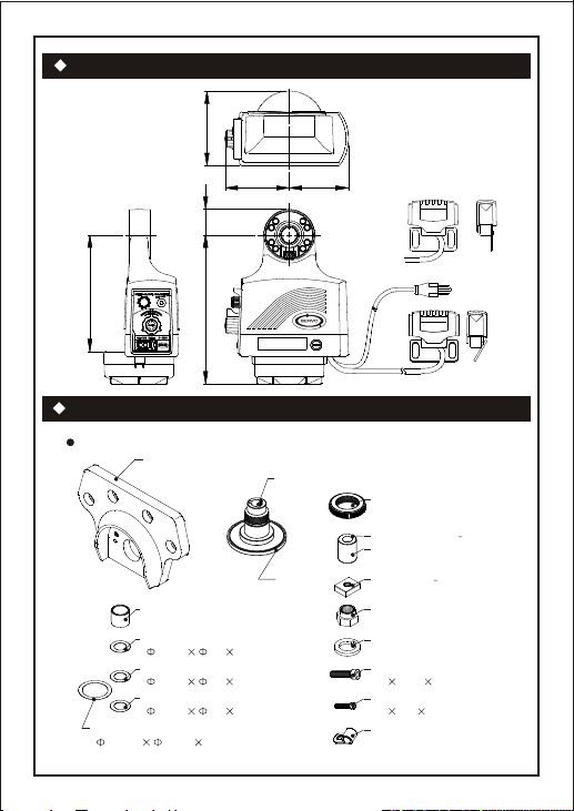
ACCESSORIES & PARTS LIST
ACCESSORIES SPECIAL FOR D-1000X & D-1000XLD
4
OUTSIDE DIMENSIONS
07256
X-AXISADAPTOR
07255
BEARINGRACE
07436CABLECLAMP
(1/4S)-1pcs
07237T-NUT2 pcs
07177HANDLEWASHER- 2pcs
07194SMALLSHIM
(1-1/32" 5/8" 0.008")-6pcs
07195SMALLSHIM-2pcs
(1-1/32" 5/8" 0.004")-2pcs
07196SMALLSHIM-3pcs
(1-1/32" 5/8" 0.040")-3pcs
07197LARGESHIM
(1-23/32" 1-5/16" 0.008")-4pcs
07176SOCKETSCREW
M6 -2pcsP1.0 25(mm)
07251NUT1/2-20
07238SOCKETSCREW
M8 P1.25 30(mm)-2pcs
07164LIMITSTOP2 pcs
59332LIMITSTOP2
LAGUN
59254DIALNUT
59331
BEVELGEARLAGUN
07159BEVELGEAR(X/Y-AXIS)
4-23/32"
1-5/8"
4-1/16" 3-3/4"
7-3/8"
9-13/32"

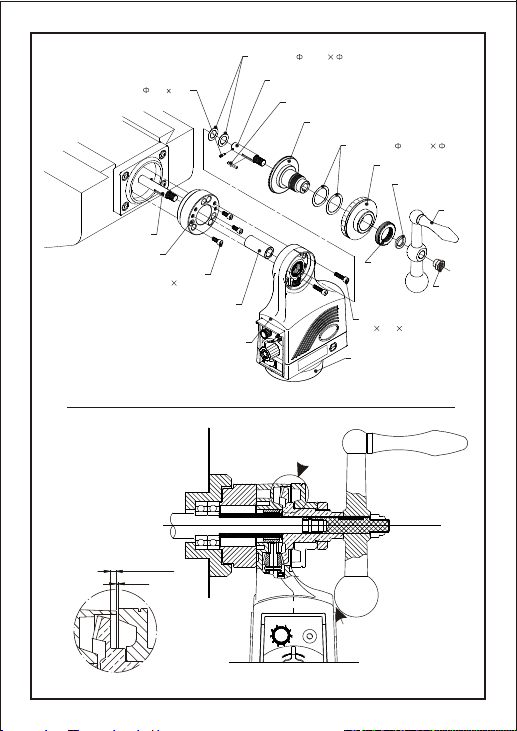
INSTALLATION
5
Step 1:Move thetableto the frontofthe knee.
Step 2:Remove thenut,crank, dial assembly,andkey fromthelead screw.
Step 3:Remove bearingretainerfrom bearing housing
Step 4:Install bearingretainersuppliedusing existingscrews.
NOTE:IF EXISTINGSCREWSARE SHORTREDRILLANDTAP1/4-20ANDINSTALL
USING 1/4-20 X1.00(3) SUPPLIED.
Step 5:Screw shaftextensiononto lead screw.Usingpilot hole drill5/32thru andinstallrollpin.
File smooth.
Step 6:Slide bearingraceon to leadscrew.Slidepower feedonto bearingrace.UsingM6
X P1.0 X25mm(2) securepowerfeedto adaptor.
TOO
D-1000Y
POWER FEED INSTALLATION
Step 1:Mount limitswitchon end ofsaddle,right handsideofmill.
Step 2:Afterdeterminingproperlocationof limitswitchusing limit switchbracketas
a template drillandtap 5/16-18(2)places.
Step 3:Install limitswitchbracket using (2)spacersand (2)5/16-18X1.50 longscrews.
Step 4:Using triprailas a template,drill andtap10-24(4) places.
Step 5:Install triprailwith(4) 10-24B.H.C.S.
LIMIT SWITCH INSTALLATION
NOTE
1. LIMIT SWITCH INSTALLATION DESIGNED FOR SERIES 1 TYPE MILLS MANUFACTURED
IN USA.
2. MOUNTING OF TRIP RAIL AND LIMIT SWITCH MAY HAVE TO BE REPOSITIONED OR
MODIFIED DEPENDING ON MANUFACTURER
Step 1:Install shimwashersapproximately.080 thickSeeFig.A
Step 2:Install key,bevelgear andcrankhandle.
BEVEL GEAR INSTALLATION
NOTE: With feed in neutral turn hand crank. If it turns freely in one direction
but catches in the other direction backlash is too large.
If rough engagement of gear is heard or fel s you require additional shims.t in both direction
Step 1:Aftergettingtheproperbacklash, thedialshouldbe adjustedtoobtain .005"
spacing from thefaceof thepowerfeed.Thisisimportantin ordertokeep chips
from entering thegeartrain. Metalwashersareprovided forthis.Shimas required.
Step 2:In thefollowingsequence, replace dialanddial lockingnut,slidethe crankonto
shaft extension andsecurewith suppliednut.
DIAL AND HANDCRANK INSTALLATION
6
C
E
C
R
D
I
O
T
I
0
N
-
SPEED-ADJUST
9 0
L
O
R
O
T
N
JOG-SWITCH
FEED 0 JOG
MUSTHAVECLEARANCE
MORETHAN0.080"
A
A
<FIG.A>
0.080~0.085"
0.005"
POWERTABLEFEED
SCREW
(M6P 1.02 5(mm))-2pcs
BEARINGRACE(Y-AXIS)
EXISTINGSCREW
1/4"-20UNC1 "-3pcs
FIXSTAND(Y-AXISADAPTOR)
AXISSHAFT
NUT
HANDLE
DIALNUT
DIAL
LARGESHIM( 1-23/32" 1-5/16")
BEVELGEAR
SMALLSHIM( 1-1/32" 5/8")
KEY
EXTENSIONSHAFT(Y-AXIS)
ROLLPIN( 5/32"9 /16")
BOTTOMCOVER
HANDLEWASHER

7
ACCESSORIES FOR D-1000Y
KNEE
00670 (2) 5/16-18 X 5/8
INSTALLED BACK SIDE
07164 (2) L/S STOP, T-NUT &
M8X1.25X30mm
SADDLE
59326 (2) L/S SPACER
59566 (1) L/S BRK'T
07160 (2) TRIP RAIL
05125 (2) 5/16-18X1.5
00622 (2) 8/32X1/2 P.H.
1004 L/S MTG PLATE
07193
10-24X3/4 B.H.C.S-4 pcs
07197LARGESHIM
(1-23/32" 1-5/16" 0.008")-4pcs
07164LIMITSTOP2 pcs
07251NUT1/2-20
07177HANDLEWASHER- 2pcs
07238SOCKETSCREW
M8 P1.25 30(mm)-2pcs
07176SOCKETSCREW
M6 -2pcsP1.0 25(mm)
07436CABLECLAMP
(1/4S)-1pcs
07257ROLLPIN
( 5/32"9 /16 -1pcs")
07258
SOCKETPARALLELKEY
00586SOCKETSCREW
1/4"-20UNC 1.0"-3pcs
05125SOCKETSCREW
5/16"-18UNC 5/8"-2pcs
07160TRIPRAIL-2pcs
07194SMALLSHIM
(1-1/32" 5/8" 0.008")-6pcs
07195SMALLSHIM-2pcs
(1-1/32" 5/8" 0.004")-2pcs
07196SMALLSHIM-3pcs
(1-1/32" 5/8" 0.040")-3pcs
07175EXTENSIONSHAFT(Y-AXIS)
07165BEARINGRACE
59254DIALNUT
07237T-NUT2 pcs
07159BEVELGEAR(X/Y-AXIS)
07162ADAPTOR(Y-AXIS)
07193SOCKETSCREW
10-24 3/4B.H.C.S-4pcs

INSTALLATION
8
Step 1:Move thetableto the frontofthe knee.
Step 2:Remove thenut,crank, dial assembly,andkey fromthelead screw.
Step 3:Remove bearingretainerfrom bearing housing
Step 4:Install bearingretainersuppliedusing existingscrews.
NOTE:IF EXISTINGSCREWSARETOSHORTREDRILLANDTAP1/4-20ANDINSTALL
USING 1/4-20 X1.00(3) SUPPLIED.
Step 5:Screw shaftextensiononto lead screw.Usingpilot hole drill5/32thru andinstallrollpin.
File smooth.
Step 6:Slide spacerontolead screw.
Step 7:saddletoward column thatthelead screw isfirmlyengaged withcross
shaft bearing.
Step 8:Slidebearing race leadscrew.Slidepower feed bearingrace.
UsingM6X P1.0X25mm (2) securepowerfeed toadaptor.
Crank ensuring
onto onto
D-1000YLD CROSS FEED
POWER FEED INSTALLATION
Step 1:Mount limitswitchon end ofsaddle,right handsideofmill.
Step 2:Afterdeterminingproperlocationof limitswitchusing limit switchbracketas
a template drillandtap 5/16-18(2)places.
Step 3:Install limitswitchbracket using (2)spacersand (2)5/16-18X1.50 longscrews.
Step 4:Using triprailas a templatedrilland tap10-24(4)places.
Step 5:Install triprailwith(4) 10-24X3/4longB.H.C.S.
LIMIT SWITCH INSTALLATION
NOTE
1. LIMIT SWITCH INSTALLATION DESIGNED FOR SERIES 1 TYPE MILLS MANUFACTURED
IN USA.
2. MOUNTING OF TRIP RAIL AND LIMIT SWITCH MAY HAVE TO BE REPOSITIONED OR
MODIFIED DEPENDING ON MANUFACTURER
Step 1:Install shimwashers,approximately .080thickSee Fig "A"
Step 2:Install key,bevelgear andcrankhandle.
BEVEL GEAR INSTALLATION
NOTE: With feed in neutral turn hand crank. If it turns freely in one direction
but catches in the other direction backlash is too large.
If rough engagement of gear is heard or felt in both directions you require
additional shims.
probably
Step 1:Aftergettingtheproperbacklash, thedialshouldbe adjustedtoobtain .005"
spacing from thefaceof thepowerfeed.Thisisimportantin ordertokeep chips
from entering thegeartrain. Metalwashersareprovided forthis.Shimas required.
Step 2:In thefollowingsequence, replace dialanddial lockingnut,slidethe crankonto
shaft extension andsecurewith suppliednut.
DIAL AND HANDCRANK INSTALLATION

KNEE
00670 (2) 5/16-18 X 5/8
INSTALLED BACK SIDE
07164 (2) L/S STOP, T-NUT &
M8X1.25X30mm
SADDLE
59326 (2) L/S SPACER
59566 (1) L/S BRK'T
07160 (2) TRIP RAIL
05125 (2) 5/16-18X1.5
00622 (2) 8/32X1/2P.H.
1004 L/S MTG PLATE
07193
10-24X3/4 B.H.C.S-4 pcs
9
#1262 SPACER (1)
#59329 ADAPTOR (1)
#59328 BEARING RACE (1)
#1169 DIAL (1)
#01318 WOODRUFF KEY (1)
5mmx6.5mm
#2418 SHAFT EXT. (1)
#00564 ROLL PIN 1/8x5/8 (1)
#59327 BEVEL GEAR (1)
FEED 0 JOGFEED 0 JOG
O
N
C
T
I
O
C
E
N
R
T
I
R
D
O
L
O
N
C
T
I
O
C
E
N
R
T
I
R
D
O
L
00

07160TRIPRAIL-2pcs
01318
WOODRUFFKEY5mmX6.5mm
07251NUT1/2-20
07177HANDLEWASHER- 2pcs
07238SOCKETSCREW
M8 P1.25 30(mm)-2pcs
07176SOCKETSCREW
M6 -2pcsP1.0 25(mm)
07436CABLECLAMP
(1/4S)-1pcs
00564ROLLPIN
( 1/8"5 /8 -1pcs")
07193SOCKETSCREW
10-24 3/4B.H.C.S-4pcs
00586SOCKETSCREW
1/4"-20UNC 1.0"-3pcs
05125SOCKETSCREW
5/16"-18UNC 5/8"-2pcs
07237T-NUT2 pcs
07197LARGESHIM
(1-23/32" 1-5/16" 0.008")-4pcs
07194SMALLSHIM
(1-1/32" 5/8" 0.008")-6pcs
07195SMALLSHIM-2pcs
(1-1/32" 5/8" 0.004")-2pcs
07196SMALLSHIM-3pcs
(1-1/32" 5/8" 0.040")-3pcs
10
ACCESSORIES FOR D-1000YLD
59329ADAPTORLAGUN
2418EXTENSIONSHAFTLAGUN
59328BEARINGRACE LAGUN
Step 1:Slide thepowerfeed onto shaftextensionand securewithM6x 25mmS.H.C.S.(2)
POWER FEED INSTALLATION
Step 1:Remove allhardwarefrom jackshaft (Handcrank,nut, dial,bearingretaineretc.)
Step 2:Mount bearingretainerwith existing screws.Ifhole patternwillnotline upusebearing
retainer as atemplate.Transferholes tomill,drill and tap1/4-20ensuring thatmounting
holes for powerfeedare inthecorrectposition.
Step 3:Secure with1/4-20x 1.00 longS.H.C.S
Step 4:Screw shaftextensiononto jackshaft andtighten.
Step 5:Slide powerfeed,bevel gear,7/8nut,spacer and handwheelto ensure youhavethe
correct stack up.
Step 6:Afterdeterminingthatyouhave thecorrectstack up removeallitems exceptshaft
extension.
Step 7: Usingpilot holeinshaft extension drill
ASALLKNEESARENOTQUITE THESAME,MODIFICATIONSMAYBEREQUIRED.
#5(.205 dia.)thruand pin withrollpin. Filesmooth.
REFERENCE DRAWINGS ENCLOSED
INSTALLATION D-1000Z
07164LIMITSTOP2 pcs
59254DIALNUT
59331BEVELGEARLAGUN

11
NOTE: With feed in neutral turn hand wheel. If it turns freely in one direction but catches
in the other direction backlash is too large.
If rough engagement of gear is heard or felt in directions you require additional shims.both
BEVEL GEAR INSTALLATION
Step 1: Installshim washersapproximately.080thick. SeeFIG.A
Step 2: Installbevel gear,nut,spacerand handwheel.
Step 1: Aftergetting thepropergear backlash, thedialshould be adjustedtoobtain .005"
spacingfromthefaceofthe powerfeed.
Thisis importantinorderto keepchipsfromentering thegeartrain. Shim asrequired.
DIAL AND HANDWHEEL INSTALLATION
Step 1: After determining correctpositionof limit switchdrilland tap 1/4"-20fortrip rail(4)places.
Step 2: Drilland tap5/16-18 inkneefor limit switchbox.
Step 3: Using5-16 x2-1/2S.H.C.S. standoffinstalllimitswitch.
(Standoffmayhaveto bemodified)
and
LIMIT SWITCH INSTALLATION
NOTE: LIMITSWITCHINSTALLATIONDESIGNEDFOR SERIESONETYPEMILLS.MOUNTING
OF TRIPRAILANDLIMITSWITCHMAYHAVETOBEREPOSITIONEDDEPENDING ON
MANUFACTURER
Check hand crank clearances before operation.
Clearancesbetween thesurfacesofthe handcrankandthe non-moving
partsof theequipmentonwhich thehandcrankis installedmustbe at
leastone-fourth inch(1/4")toprevent injury.Modificationof existing
handcrank orreplacementmaybe required.
Do not operate withoutproper clearance!
Preventcontact duringfasttraverses.
WARNINGS
O
E
O
C
I
T
-
N
0
C
L
O
R
N
T
0JOG-SWITCH
FEED 0 JOG
9
R
D
I
SPEED-ADJUST
12
<FIG.A>
0.080~0.085"
0.005"
A
B
(ROLLPIN)
1685-1 HANDWHEEL(1)
7/8-14NUTTHREAD
DIALNUT
DIAL
LARGESHIM( 1-23/32 1-5/16")
BEVELGEAR(Z-AXIS)
SMALLSHIM( 1-7/32 7/8")
P/N00586
(1/4"-201 "S.H.C.S)-3pcs
P/N59333
ADAPTOR(Z-AXIS)
SCREW
(M6P 1.02 5(mm))-2pcs
AXISSHAFT
KEY
4 4 25(mm)
POWERTABLEFEED
BOTTOMCOVER
EXTENSIONSHAFT(Z-AXIS) KEY
(1/8" 1/8" 1-1/4")
SPACER
1"O.D. 5/8"I.D. 1-1/16LONG
ROLLPIN
( 0.2" 3/4")
13
07176SOCKETSCREW
M6 -2pcsP1.0 25(mm)
07436CABLECLAMP
(1/4S)-1pcs
07274ROLLPIN
( 0.2 3/4 -1pcs)
59496SOCKETPARALLELKEY
4425(mm)-1pcs
07193SOCKETSCREW
10-24 3/4B.H.C.S-4pcs
00586SOCKETSCREW
1/4"-20UNC 1.0"-3pcs
07237T-NUT2 pcs
57162SOCKETPARALLELKEY
1/8" 1/8" 1-1/4"-1pcs
07238SOCKETSCREW
M8 P1.25 30(mm)-2pcs
05292SOCKETSCREW
5/16"-18UNC 2-1/2"-2pcs
07261STANDOFF
L/S1/2O.D. 3/8I.D. 2.2LG.
07260HEXNUT7/8-14
(Z-AXIS)
59333ADAPTOR(Z-AXIS)
ACCESSORIES FOR D-1000Z
07197LARGESHIM
(1-23/32" 1-5/16" 0.008")-4pcs
07164LIMITSTOP2 pcs
07160TRIPRAIL-2pcs
59254DIALNUT
59331BEVELGEARLAGUN
07233SMALLSHIM
( 1-7/32 7/8" 0.008")-4pcs
07234SMALLSHIM-2pcs
(1-7/32 7/8" 0.004")-2pcs
07235SMALLSHIM-3pcs
(1-7/32 7/8" 0.040")-2pcs
07167BEVELGEAR(Z-AXIS)
07259
HANDWHEELSPACER
07166EXTENSIONSHAFT(Z-AXIS)
KNEE
07164 (2) L/S STOP
07160 (2) TRIP RAIL
STANDOFF.
1/2"O.D. 3/8"I.D. 2.2LG.-2pcs
P/N05292
5/16-18 2-1/2S.H.C.S.-2pcs
07193
10-24 3/4B.H.C.S-4pcs
07237T-NUT
M8P 1.253 0mm
07238

14
1.Set"jog switch"at"FEED" position. Setspeed-adjustbetween 2and3.Set directioncontrol
knobto0position.
2.Turnonpower switch,turndirectionalcontrol toleftorright tocheckpower feed ismoving
intherightdirection.
3.Depresslimit switchindirection of travel,repeatin oppositedirectiontoensure limit
switchisstopping powerfeed.
CHECKING & CONFIRMING
POWER SWITCH AND RESET SWITCH
1.Theright sideofpower switch is ON. Theleft sideisOFF. Theredlightwill showwhen
poweris ON.
2.Thered oblong buttononright side isresetswitch
AVAILABLE FOR LONGITUDINAL / CROSS / KNEE TRAVEL
POWER CONNECTION
1.Powerfeed requires120VAC50/60Hz electrical service. Pleasebesure inputpower
isin compliancewiththis requirement. Iftheinput powerisnot120VAC50/60Hzpleaseuse an
appropriatetransformer.Failuretousethe correctpowerwill damage thepowerfeed andcan
createa dangerousconditionresultingin injuryordeath.
2.Pleaseavoid cableexposureto high temperature,highhumidity oranysharpobjects.
3.Tumoffpowerswitchbypressing leftsideofswitch. Connectplugto 120VAC50/60Hz.
Useathreeprong groundedoutletonly.
OPERATION (FIG.10)
JOGSWITCH
DIRECTIONCONTROL
RAPIDBUTTON
SPEEDADJUST KNOB
POWERSWITCH
RESETSWITCH
<FIG.10>

15
MAINTENANCE
Note: After operating jog switch, turn "DIRECTION CONTROL" to "0"
position. Then move "JOG SWITCH" to "0" "FEED"
position.
2.Besure tofollowthe above procedurerequiredfor jogoperationtoavoid anydamageorinjury
roperoperation.causedby imp
JOG SWITCH
1.Forjog movement,movejog switch to0position
2.Setspeed-adjustto0
3.Setdirection-controltodirection youwantpower feed tomove.
4.Theamountpowerfeed willmovedepends on speedsetting.Thesmallerthesetting theless
thepowerfeedwill move.The higher thespeedsetting thefurtherthepower feedwillmove.
5.Togglethe jogswitchtojog positionandrelease,the powerfeedwill stop.Ifyouhold jogswitch
powerfeedwillcontinue tomoveuntil released.
6.Afterobtainingpowerfeed position,setjog switch to0position anddirection-controlto0 position.
7.Setjogswitchto feedposition.Youcanbeginnormalmachining.
1.Thespeed canbeadjusted according tooperator'srequirement. The speedrangeis0 to9.
SPEED ADJUST KNOB
DIRECTION CONTROL AND RAPID BUTTON
1.Positiondirection-control todirectionyou want thepowerfeed tomove.
2.Therapid buttonisin the centerofdirection-control.
MAINTENANCE FOR GEAR LUBRICATION (FIG.11)
Every6 months,openthe bottom cover,andcheckif lubricationforbevel spiralgearis
sufficient. Itissuggestedto use graphitetypelubrication, donotusesilicone typelubrication.
CHECKING FOR GEAR WEAR (FIG. 11)
Tocheckthecondition ofspiralgear(made ofplastic107T)remove bottomgearcover. If
gearisworn out,pleasereplacewith anewgear. Theprocedure toreplacethe gear isasfollows:
1.Openthe bottomcover(pressthe edgeofhooks on bothsides,and pulldown.)
2.Loosenlock nut,sequentiallytakeout washer,adaptorass'y,roll pin, spacerwasher,
Gearass'yandthrust bearing.
3.Disassemblegear ass'y,replacebevel spiralgear,andthen installitback sequentially.
4.Thepressure plateassemblyandsurface ofGearAssemblymust bekeptclean, and cannot
contain oil. Ifthereis any oil,pleaseclean itwithsolvent,do notcleanwithwater.
CHECKING FOR CARBON BRUSH WEAR (FIG. 12)
Inevery 6months,opencarbon brushcap,to check ifbrushis wornout.Ifthe lengthofthe
brushis lessthan0.2",the brushesmustbe replaced immediately.

16
CARBONBRUSHCAP
CARBONBRUSH
NOTLESSTHAN 0.2"
<FIG.12>
<FIG.11>
MOTORSHAFT
07247THRUSTBEARING
BOTTOMGEAR
GEARASSY'
07262NEEDLEPIN
( .12 .56")
07248
SPACERBOTTOMGEAR
ADAPTERASS'Y
07249
WASHERBOTTOM GEAR
07250
LOCKNUTBOTTOM GEAR
BOTTOMCOVER
DRIVESHAFT
CLUTCH'
SPIRALGEAR
ASS'YBOTTOMGEAR
07245
07264BUSHINGB.G.(3)
07265SCREWB.G.(3)
PRESSUREPLATEASS'Y
ADAPTER
07246ASS'YBOTTOM
GEARADAPTER
07269WASHERB.G. (3)
07268SCREWSB.G.(3)

17
PARTS LIST
No
.
1
2
3
4
5
6
7
8
9
10
11
12
13
14
15
16
17
18
19
20
21
22
23
24
25
26
27
28
29
30
31
TOPHOUSING
NEEDLEBEARING
BEVELGEARSET(18T)
THRUSTBEARING
TALLOYBRASS
MOTORBRACKET
ARMATURESET
STATORSET
CIRCUITBOARDSET
SWITCHBRACKETSET
SPEEDADJUSTKNOB
JOGSWITCHSET
MICROSWITCH
BOTTOMHOUSING
CARBONBRUSHHOLDER
CARBONBRUSH
CARBONBRUSHCOVER
TALLOYBRASS
MAGNETICYORKSET
POWERCABLE
LIMITSWITCHSET
YORKSET
SPIRALGEAR(107T)
OCCLUSIONSOFTSET
ADAPTER
GEARHOUSING
LIMITSWITCHCOVERSET
BOTTOMGEARASSY
JOGSWITCHBOOT
ON/OFFSWBOOT
ON/OFFSWITCH
PARTNAME
MECHANICALPARTS
PARTNO.
29 11 30 31 10 12
1
2
9
13
4
22
23
28
24
25
21
26
27
19
18
17
16
15
14 15 16 17
20
8
57
4
3
6

1.Check ifpowerisplugged in
1.Checkjog switchisin
"FEED"position?
1.Openbottom cover,checkthe
motorshaft&gear shaftnot
engaged.
Check poweroutlet& plug.
Turndirection-control to0off
position.Move jogswitchto feed
positionand restartpowerfeed
Checking Solution
Condition
ON/OFFlight isnot
ON,power tablefeed
isnot working.
ON/OFFlight isON,
Powerfeed isnot
working
Powerfeed slipping
Clutch woreout,to replaceyorkset
andocclusion softset(FIG. 11)?
Openthecarbon brushcapsand
replacetwo carbonbrushes.
Replacespiralgear.(FIG.11)?
2.Speedadjust knobat "0"
Position?
2.ON/OFFswitch atONposition.
3.Resetswitch ispoppedup.
Press theswitchto ON position.
(Redlight isON)
Reduce toolload,press reset
Switch,restart thepowerfeed
Turnthespeedadjustknob clockwise
directionuntil therequiredspeed
achieved.
2.Openbottom coverandcheck
ifspiralgearis wornout.
3.Carbonbrush woreout.
(Lessthan 0.2".)
TROUBLESHOOTING
18
SERVO PRODUCTS CO
FLORIDABRANCH
st
8950 131 Ave. N.
Largo, FL 33773
Ph. 727 585 8555
Fax 727 585 6555
HEADQUARTERS
34940 Lakeland Blvd.
Eastlake, OH 44095
Ph. 800 521 7359
Fax 400 942 9100
CALIFORNIABRANCH
14254 Valley Blvd
City of Industry, CA91746
Ph. 626 961 7800
Fax 626 961 2444
. UnitA
A HIGH QUALITY TOOLS Partner Company
2008.10
This manual suits for next models
4
Table of contents


