FMS BKS015.EIP User manual

Operating Manual BKS015.EIP
Steering Frame with Digital Web Guide Controller with
EtherNet/IP Interface
Version 2.14 11/2018 NS
Firmware Version V2.21
Diese Bedienungsanleitung ist auch in Deutsch erhältlich.
Bitte kontaktieren Sie Ihren nächstgelegenen FMS Vertreter.
© by FMS Force Measuring Systems AG, CH-8154 Oberglatt – All rights reserved.

Operating Manual BKS015
26.11.2018 2
Table of Contents
1 Safety Instructions ..................................................................................... 4
1.1 Description Conditions 4
1.2 List of Safety Instructions 4
2 System Description .................................................................................... 5
2.1 Functional Description 5
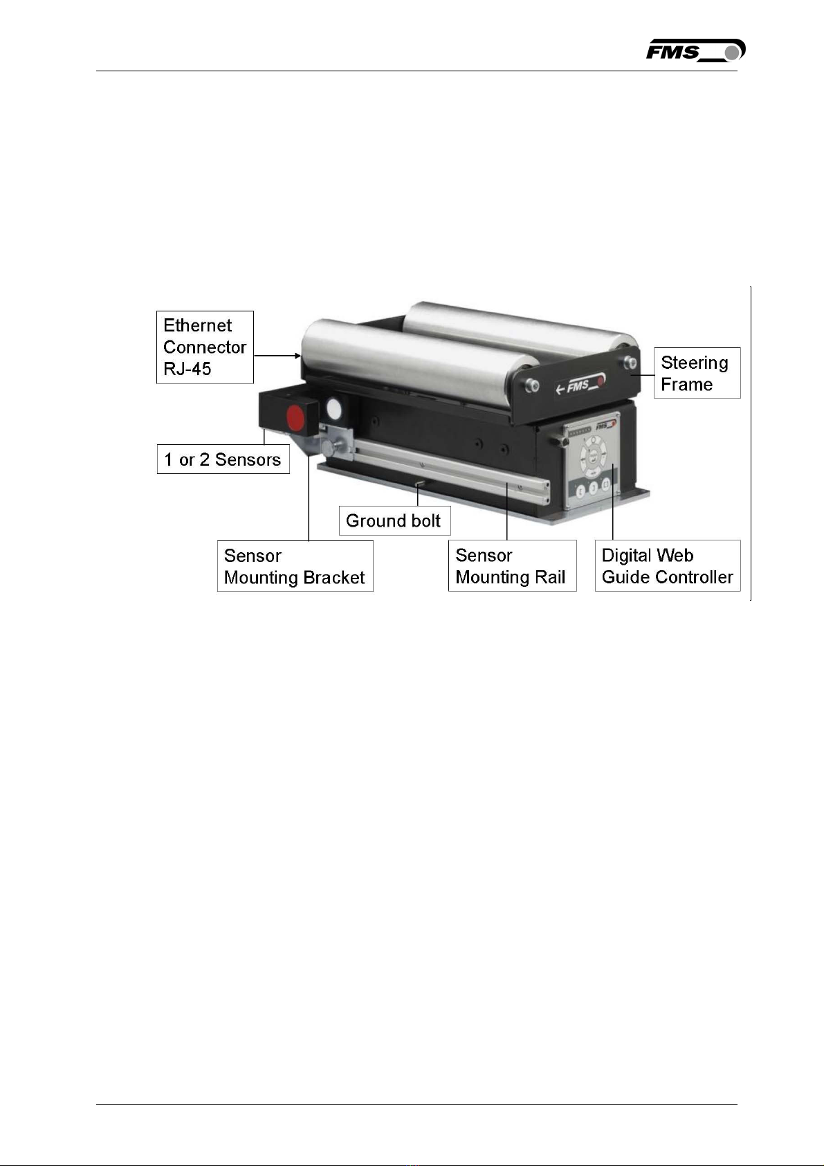
2.2 Steering Frame 5
2.3 Web Guide Controller 5
2.4 Sensors 5
2.5 Cables 6
2.6 System Integration in an Ethernet Network 6
3 Quick Installation Guide ............................................................................. 6
3.1 Preparations for Set-up 6
3.2 Installation Procedure 7
4 Installation and Wiring ............................................................................... 8
4.1 Mounting the Steering Frame 8
4.2 Mounting the Sensors 8
4.3 Connecting the BKS015.EIP 9
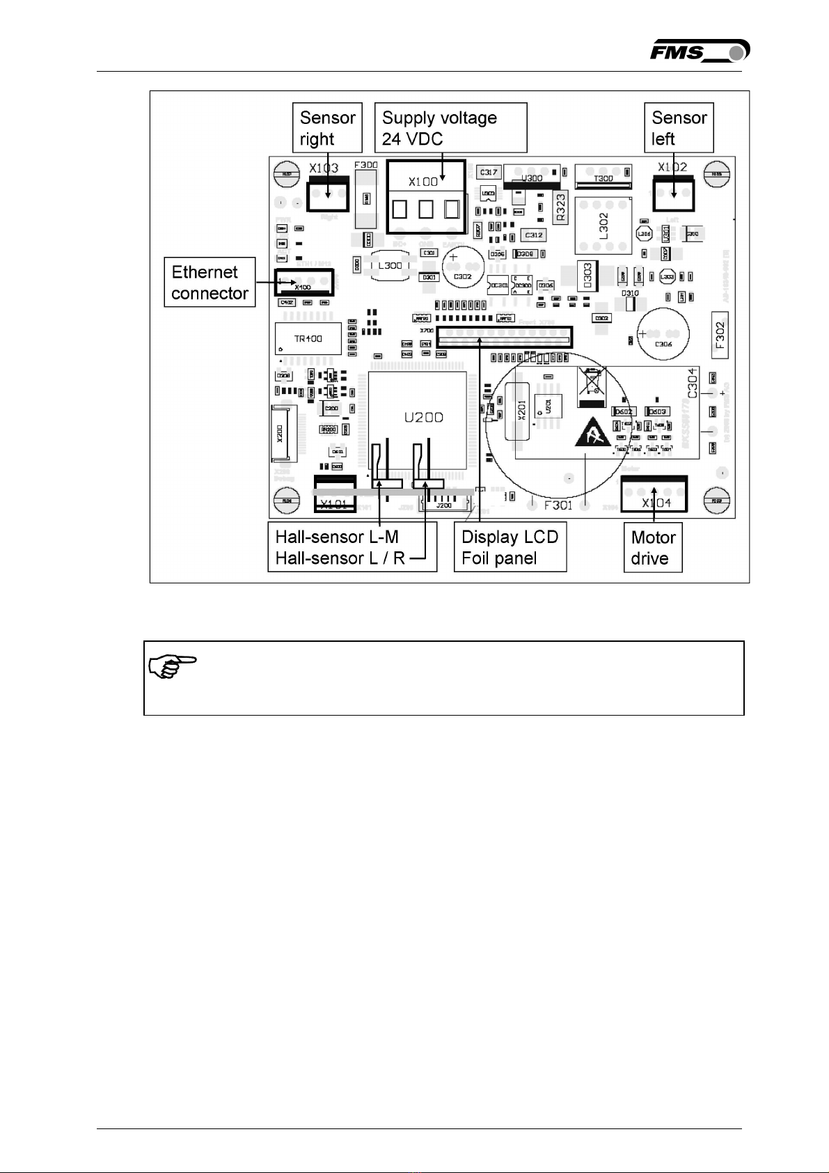
4.4 Connector and Screw Terminal Arrangement 9
5 Configuring the System ............................................................................ 11
5.1 Powering up the BKS015.EIP 11
5.2 Adjustment of the Sensors 11
6 Network Connection over EtherNet/IP ................................................... 12
6.1 EtherNet/IP Specification: 12
6.2 Controller Functionality over EtherNet/IP 12
6.3 Integration of BKS015.EIP in an Ethernet Network 12
6.4 Configuration of the Web Guide Controller over EtherNet/IP 12
7 Integration in an Allen-Bradley PLC ........................................................ 14
7.1 Hardware Environment 14
7.2 IP Configuration 14
7.3 Integration in a Project 14
7.4 Access to the Status Information 17
8 Operation .................................................................................................. 19
8.1 Operation Panel 19
8.2 Basic Instructions for Operation and Parameter Setting 19
8.3 Operating the Web Guiding System via the Front Panel 19
8.4 Operation in Automatic Mode 21
8.5 Operation in Manual Mode 22
8.6 Entering the Parameter Setting Mode 22
8.7 Description of the LED-row 23
8.8 Sensor Detection Range and Reference Position 24
9 Description Parameters ........................................................................... 25
9.1 Description Operation Parameters 25
9.2 Description of System Parameters 28
9.3 Reset to Default Parameter Set 30

Operating Manual BKS015
26.11.2018 3
10 Parameter Setting via a PC...................................................................... 31
10.1 Parameterization in a Network via Web Browser 31
10.2 Parameterization via a PC (peer-to-peer connection) 35
11 Dimensions ............................................................................................... 39
12 Trouble Shooting ...................................................................................... 41
13 Technical Specification ............................................................................ 42

Operating Manual BKS015
26.11.2018 4
1 Safety Instructions
1.1 Description Conditions
a) Danger of health injury or loss of life
Danger
This symbol refers to high risk for persons to get health injury or loss life. It has to
be followed strictly.
b) Risk of damage of machines
Caution
This symbol refers to information, that, if ignored, could cause heavy mechanical
damage. This warning has to be followed absolutely.
c) Note for proper function
Note
This symbol refers to an important information about proper use. If not followed,
malfunction can be the result.
1.2 List of Safety Instructions
Proper function of the FMS web guide is only guaranteed with the recommended
application of the components. In case of other arrangement, heavy malfunction
can be the result. Therefore, the installation instructions on the following pages
must be followed strictly.
Local installation regulations are to preserve safety of electric equipment. They are
not taken into consideration by this operating manual. However, they have to be
followed strictly.
Make sure that the sensor(s) are connected properly to the electronic unit by
means of the delivered cables. For left / right orientation please refer to Fig. 2. If
the connections are crossed over, malfunction can be the result.
System parameters are factory settings and should not be changed without
contacting the service department of FMS. An unauthorised change can cause
malfunctions in the system or damage in the machine

Operating Manual BKS015
26.11.2018 5
2 System Description
2.1 Functional Description
Figure 1 shows the BKS015 web guiding system with its basic components.
The sensors measure the position of the web edge and send this information as an
analogue signal to the built-in web guide controller unit. The control compares the
position feedback signal with the reference. If the difference of these two values is
higher then the stored dead band value, the steering frame will be adjusted.
Fig. 1: Basic BKS015.EIP system K015006e
2.2 Steering Frame
The steering frame consists of a fixed lower and a moveable upper frame that
supports the rollers. The upper frame is activated by a stepper motor. The rollers
are manufactured and balanced according to customer specification. End positions
are controlled by hall sensors. The material sensors are mounted on the lower
frame by means of a bracket array and are easily adjustable to the web width.
2.3 Web Guide Controller
The micro-processor based electronic control unit handles all calculations and
communications tasks. Three buttons and a five key wind-rose serve as the man-
machine interface. Parameter setting can be performed via the front panel or
through a Web Browser (IE 7.0 or higher) or via the EtherNet/IP.
2.4 Sensors
Optical sensors (AZS04) and ultrasonic sensors (US01B) are available from FMS to
work in conjunction with the BKS015.EIP system. These sensors provide a signal of
0...10V. With them edge and center applications can be covered. A wide range of
Table of contents
Other FMS Industrial Equipment manuals